EP1219977A1 - Rod lens having inclined surface - Google Patents
Rod lens having inclined surface Download PDFInfo
- Publication number
- EP1219977A1 EP1219977A1 EP01130502A EP01130502A EP1219977A1 EP 1219977 A1 EP1219977 A1 EP 1219977A1 EP 01130502 A EP01130502 A EP 01130502A EP 01130502 A EP01130502 A EP 01130502A EP 1219977 A1 EP1219977 A1 EP 1219977A1
- Authority
- EP
- European Patent Office
- Prior art keywords
- end surface
- rod lens
- optical element
- rod
- central axis
- Prior art date
- Legal status (The legal status is an assumption and is not a legal conclusion. Google has not performed a legal analysis and makes no representation as to the accuracy of the status listed.)
- Withdrawn
Links
Images

Classifications
-
- G—PHYSICS
- G02—OPTICS
- G02B—OPTICAL ELEMENTS, SYSTEMS OR APPARATUS
- G02B6/00—Light guides; Structural details of arrangements comprising light guides and other optical elements, e.g. couplings
- G02B6/24—Coupling light guides
- G02B6/26—Optical coupling means
- G02B6/28—Optical coupling means having data bus means, i.e. plural waveguides interconnected and providing an inherently bidirectional system by mixing and splitting signals
- G02B6/293—Optical coupling means having data bus means, i.e. plural waveguides interconnected and providing an inherently bidirectional system by mixing and splitting signals with wavelength selective means
- G02B6/29346—Optical coupling means having data bus means, i.e. plural waveguides interconnected and providing an inherently bidirectional system by mixing and splitting signals with wavelength selective means operating by wave or beam interference
- G02B6/29361—Interference filters, e.g. multilayer coatings, thin film filters, dichroic splitters or mirrors based on multilayers, WDM filters
-
- G—PHYSICS
- G02—OPTICS
- G02B—OPTICAL ELEMENTS, SYSTEMS OR APPARATUS
- G02B13/00—Optical objectives specially designed for the purposes specified below
- G02B13/0095—Relay lenses or rod lenses
-
- G—PHYSICS
- G02—OPTICS
- G02B—OPTICAL ELEMENTS, SYSTEMS OR APPARATUS
- G02B3/00—Simple or compound lenses
- G02B3/0087—Simple or compound lenses with index gradient
-
- G—PHYSICS
- G02—OPTICS
- G02B—OPTICAL ELEMENTS, SYSTEMS OR APPARATUS
- G02B6/00—Light guides; Structural details of arrangements comprising light guides and other optical elements, e.g. couplings
- G02B6/24—Coupling light guides
- G02B6/26—Optical coupling means
- G02B6/32—Optical coupling means having lens focusing means positioned between opposed fibre ends
-
- G—PHYSICS
- G02—OPTICS
- G02B—OPTICAL ELEMENTS, SYSTEMS OR APPARATUS
- G02B6/00—Light guides; Structural details of arrangements comprising light guides and other optical elements, e.g. couplings
- G02B6/24—Coupling light guides
- G02B6/26—Optical coupling means
- G02B6/32—Optical coupling means having lens focusing means positioned between opposed fibre ends
- G02B6/327—Optical coupling means having lens focusing means positioned between opposed fibre ends with angled interfaces to reduce reflections
Definitions
- the present invention relates to an optical element, such as a gradient-index rod-lens and a capillary. More particularly, the present invention pertains to an optical element having at least one end surface that is inclined with respect to a central axis of the rod lens or the capillary.
- a typical gradient-index rod-lens converts light that is sent from a light source, such as a laser diode and a light emitting diode (LED), to a parallel light or converges light that is received through an optical fiber at a predetermined position.
- a light source such as a laser diode and a light emitting diode (LED)
- LED light emitting diode
- two rod lenses are arranged to contact each other.
- a filter which has desired optical characteristics, is placed between two rod lenses.
- the lens length of the rod lens is determined according to the intended purpose of the rod lens. For example, the lens length of the rod lens is set in accordance with the distance between the output end of the optical fiber and the rod lens or the distance between the two rod lenses such that the coupling loss is minimized.
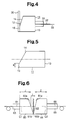
- Fig. 6 illustrates conventional rod lenses 60, 61 used in an optical communication module.
- the rod lens 60 on the left side has an output side end surface 60a, which is inclined with respect to a central axis C1 of the rod lens 60.
- the rod lens 61 on the right side has an input side end surface 61a, which is inclined with respect to a central axis C2 of the rod lens 61.
- An optical fiber 64 is held by a capillary 63 and an optical fiber 66 is held by a capillary 65.
- a filter 62 is placed between a distal end portion 60b of the rod lens 60 and a distal end portion 61b of the rod lens 61.
- the rod lens 60 converts light that is emitted from the output end of the optical fiber 64 to a parallel light.
- the parallel light is transmitted through the filter 62 and enters the rod lens 61.
- the rod lens 61 converges the parallel light at the input end of the optical fiber 66.
- the converged light travels through the optical fiber 66 and is sent to another optical element.
- the two rod lenses 60, 61 optically couple the two optical fibers 64, 66.
- the lens length Z of the rod lens 60 is the length of the central axis C1 between both end surfaces.
- the lens length Z of the rod lens 61 is the length of the central axis C2 between both end surfaces.
- the distance L between the two rod lenses 60, 61 is the distance between the output side end surface 60a and the input side end surface 61a along the central axes C1, C2.
- the distal end portions 60b, 61b of the conventional rod lenses 60, 61 are sharp and easily damaged.
- the distal end portions 60b, 61b could get chipped when placing the filter 62 between the distal end portions 60b, 61b, or when the distal end portions 60b, 61b are arranged to contact each other. If the distal end portions 60b, 61b get chipped, the distance L changes. Therefore, the lens length Z, which is optimized in accordance with the distance L before the distal end portions 60b, 61b get chipped, is not optimum.
- the optical communication module that uses the rod lenses 60, 61 having chipped distal end portions 60b, 61b has great coupling loss.
- the optical fibers 64, 66 are not optically coupled in the optimum manner. Also, when inserting the rod lenses 60, 61 into a holder such as a cylindrical sleeve, the sharp distal end portions 60b, 61b could contact the holder and get chipped. In this case, the optical module is defective. Similar problem occurs when the end surface of each capillary 63, 65 is inclined. If the sharp distal end portions of the rod lenses 60, 61 or the capillaries 63, 65 get chipped, the chipped pieces could further increase the coupling loss.
- the objective of the present invention is to provide an optical element for an optical communication module that is not easily damaged, improves the defect rate, and reduces the coupling loss.
- Another objective of the present invention is to provide an optical element for an optical communication module that minimizes the coupling loss without performing alignment during the assembly of various types of optical modules.
- the optical element includes a first end surface and a second end surface. At least one of the first end surface and the second end surface includes an inclined surface, which is inclined by a predetermined angle with respect to a central axis of the optical element, and a distal end surface, which is adjacent to the inclined surface.
- the present invention also provides a cylindrical optical element.
- the cylindrical optical element includes a first end surface, a second end surface, and an outer circumferential surface.
- the first end surface intersects a central axis of the optical element.
- the second end surface intersects the central axis.
- the outer circumferential surface extends along the central axis.
- At least one of the first end surface and the second end surface includes an inclined surface, which is inclined by a predetermined angle with respect to the central axis of the optical element, and a contact surface, which is adjacent to the inclined surface and is perpendicular to the central axis.
- a term “optical element” includes a gradient-index rod-lens, a capillary, which holds an optical fiber, and an optical member such as an optical crystal used for, for example, an optical isolator.
- an optical member such as an optical crystal used for, for example, an optical isolator.
- a term “effective diameter of a rod lens” refers to the maximum diameter of a lens that provides an optical aberration that is less than or equal to a predetermined value.
- FIG. 2 is a view looking at the rod lens 11 shown in Fig. 1 from a direction indicated by an arrow A.
- the rod lens 11 is a cylindrical glass having a predetermined gradient index.
- the rod lens 11 has an input side end surface 12 and an output side end surface 13.
- the output side end surface 13 is a flat surface that is perpendicular to a central axis C3 of the rod lens 11.
- the input side end surface 12 includes an inclined surface 14 and a contact surface 15.
- the inclined surface 14 is inclined by a predetermined inclination angle ⁇ with respect to the central axis C3.
- the contact surface 15 is a distal end portion that is adjacent to the inclined surface 14.
- the contact surface 15 is preferably a flat surface that is perpendicular to the central axis C3.
- the outer circumferential surface of the rod lens 11 and the contact surface 15 preferably form an angle of at least 90 degrees in relation to each other.
- the lens length (light path length) Zl of the rod lens 11 is determined in accordance with the gradient index characteristics ( ⁇ A) of the rod lens 11 and the distance L (see Fig. 3) required by an application (an optical communication module) in which the rod lens 11 is used.
- the contact surface 15 and the inclined surface 14 are formed on the input side end surface 12 of the rod lens 11 such that the rod lens 11 has the determined lens length Zl. More specifically, the dimension h of the contact surface 15, which is perpendicular to the central axis C3, is determined in accordance with the lens length Z1 and the distance L.
- the inclination angle ⁇ of the inclined surface 14 is determined such that the distal end portion of the input side end surface 12 has the contact surface 15, which has the dimension h.
- the contact surface 15 is preferably formed outside an effective diameter area 17 of the rod lens 11.
- Fig. 3 shows the rod lens 11 used in an optical communication module.
- the optical communication module includes the rod lens 11 and a rod lens 11A, which is a mirror image of the rod lens 11.
- the rod lens 11A has the same structure as the rod lens 11.
- the rod lens 11 and the rod lens 11A are coaxial.
- the input side end surface 13A of the rod lens 11A is a flat surface that is perpendicular to the central axis C4 of the rod lens 11A.
- the output side end surface 12A of the rod lens 11A includes the inclined surface 14A and the contact surface 15A.
- the inclined surface 14A is inclined by the predetermined inclination angle ⁇ with respect to the central axis C4.
- the contact surface 15A is perpendicular to the central axis C4.
- a filter 16 is located between the contact surface 15A of the rod lens 11A and the contact surface 15 of the rod lens 11.
- a capillary 20, which holds an optical fiber 21, is secured to the input side end surface 13A of the rod lens 11A.
- a capillary 22, which holds an optical fiber 23, is secured to the output side end surface 13 of the rod lens 11.
- the rod lens 11A converts the light that is emitted from the optical fiber 21 to a parallel light and emits the parallel light to the filter 16.
- the light that is transmitted through the filter 16 is converged by the rod lens 11.
- the converged light enters the optical fiber 23 and is sent to another optical element, which is not shown.
- the two rod lenses 11A, 11 optically couple the two optical fibers 21, 23.
- the rod lenses 11A, 11 according to the preferred embodiment provides the following advantages.
- optical fibers 32, 33 are optically coupled in the optimum manner by only arranging the reflection surface of the mirror 30 to contact the contact surface 15 of the rod lens 11. Therefore, the coupling loss is minimized without performing alignment of the rod lens 11 with respect to the mirror 30.
- the present invention is applied to the gradient-index rod-lens 11, 11A.
- the present invention may be applied to any one of the capillaries 20, 22, 31, which hold the optical fibers 21, 23, 32, 33. That is, the inclined surface and the distal end, which is adjacent to the inclined surface and has no sharp edge, may be formed on at least one of the ends of the capillary 20, 22, 31.
- the distal end is preferably a flat surface that is perpendicular to the optical axis of the capillary 20, 22, 31 as the contact surface 15. In this case, the distal end of the capillary 20, 22, 31 does not easily get chipped even when the distal end contacts the cylindrical holder such as the sleeve. This improves the defect rate during manufacturing of various types of optical modules.
- the contact surface 15 may be curved.
- the inclined surface 14 and the contact surface 15 may be formed on both end surfaces 12, 13 of the rod lens 11.
- an inclined surface may be formed on the input side end surface 13A of the left side rod lens 11A. Then, an inclined surface, which corresponds to the inclined surface of the input side end surface 13A, may be formed on the end surface of the left side capillary 20. In this case, the inclined surface of the rod lens 11A and the inclined surface of the capillary 20 are located with a predetermined space in between.
- the right side capillary 22 and the right side rod lens 11 may be formed in the same manner.
- the rod lens 11 need not be cylindrical.
- the rod lens 11 may be square.
Landscapes
- Physics & Mathematics (AREA)
- General Physics & Mathematics (AREA)
- Optics & Photonics (AREA)
- Optical Couplings Of Light Guides (AREA)
Abstract
A rod lens (11, 11A) for an optical communication module is not easily damaged. An input side end surface (12, 12A) of the rod lens (11, 11A) has an inclined surface (14, 14A). The inclined surface (14, 14A) is inclined by a predetermined angle with respect to a central axis (C3, C4) of the rod lens (11, 11A) to reduce the reflection loss. A flat contact surface (15, 15A), which is perpendicular to the central axis (C3, C4), is formed on the distal end of the rod lens (11, 11A). By simply arranging two of the rod lenses (11, 11A) to contact each other, the rod lenses (11, 11A) are optically coupled in the optimum manner without being damaged. <IMAGE>
Description
The present invention relates to an optical element,
such as a gradient-index rod-lens and a capillary. More
particularly, the present invention pertains to an optical
element having at least one end surface that is inclined with
respect to a central axis of the rod lens or the capillary.
A typical gradient-index rod-lens converts light that is
sent from a light source, such as a laser diode and a light
emitting diode (LED), to a parallel light or converges light
that is received through an optical fiber at a predetermined
position. To transmit light from one optical fiber to
another, two rod lenses are arranged to contact each other.
Alternatively, a filter, which has desired optical
characteristics, is placed between two rod lenses. The lens
length of the rod lens is determined according to the intended
purpose of the rod lens. For example, the lens length of the
rod lens is set in accordance with the distance between the
output end of the optical fiber and the rod lens or the
distance between the two rod lenses such that the coupling
loss is minimized.
Fig. 6 illustrates conventional rod lenses 60, 61 used
in an optical communication module. The rod lens 60 on the
left side has an output side end surface 60a, which is
inclined with respect to a central axis C1 of the rod lens 60.
The rod lens 61 on the right side has an input side end
surface 61a, which is inclined with respect to a central axis
C2 of the rod lens 61.
An optical fiber 64 is held by a capillary 63 and an
optical fiber 66 is held by a capillary 65. A filter 62 is
placed between a distal end portion 60b of the rod lens 60 and
a distal end portion 61b of the rod lens 61. The rod lens 60
converts light that is emitted from the output end of the
optical fiber 64 to a parallel light. The parallel light is
transmitted through the filter 62 and enters the rod lens 61.
The rod lens 61 converges the parallel light at the input end
of the optical fiber 66. The converged light travels through
the optical fiber 66 and is sent to another optical element.
The two rod lenses 60, 61 optically couple the two optical
fibers 64, 66.
The lens length Z of the rod lens 60 is the length of
the central axis C1 between both end surfaces. The lens
length Z of the rod lens 61 is the length of the central axis
C2 between both end surfaces. The distance L between the two
rod lenses 60, 61 is the distance between the output side end
surface 60a and the input side end surface 61a along the
central axes C1, C2.
The distal end portions 60b, 61b of the conventional rod
lenses 60, 61 are sharp and easily damaged. For example, the
distal end portions 60b, 61b could get chipped when placing
the filter 62 between the distal end portions 60b, 61b, or
when the distal end portions 60b, 61b are arranged to contact
each other. If the distal end portions 60b, 61b get chipped,
the distance L changes. Therefore, the lens length Z, which
is optimized in accordance with the distance L before the
distal end portions 60b, 61b get chipped, is not optimum.
Thus, the optical communication module that uses the rod
lenses 60, 61 having chipped distal end portions 60b, 61b has
great coupling loss. Accordingly, the optical fibers 64, 66
are not optically coupled in the optimum manner. Also, when
inserting the rod lenses 60, 61 into a holder such as a
cylindrical sleeve, the sharp distal end portions 60b, 61b
could contact the holder and get chipped. In this case, the
optical module is defective. Similar problem occurs when the
end surface of each capillary 63, 65 is inclined. If the
sharp distal end portions of the rod lenses 60, 61 or the
capillaries 63, 65 get chipped, the chipped pieces could
further increase the coupling loss.
The objective of the present invention is to provide an
optical element for an optical communication module that is
not easily damaged, improves the defect rate, and reduces the
coupling loss.
Another objective of the present invention is to provide
an optical element for an optical communication module that
minimizes the coupling loss without performing alignment
during the assembly of various types of optical modules.
To achieve the foregoing objective, the present
invention provides an optical element. The optical element
includes a first end surface and a second end surface. At
least one of the first end surface and the second end surface
includes an inclined surface, which is inclined by a
predetermined angle with respect to a central axis of the
optical element, and a distal end surface, which is adjacent
to the inclined surface.
The present invention also provides a cylindrical
optical element. The cylindrical optical element includes a
first end surface, a second end surface, and an outer
circumferential surface. The first end surface intersects a
central axis of the optical element. The second end surface
intersects the central axis. The outer circumferential
surface extends along the central axis. At least one of the
first end surface and the second end surface includes an
inclined surface, which is inclined by a predetermined angle
with respect to the central axis of the optical element, and a
contact surface, which is adjacent to the inclined surface and
is perpendicular to the central axis.
Other aspects and advantages of the invention will
become apparent from the following description, taken in
conjunction with the accompanying drawings, illustrating by
way of example the principles of the invention.
The invention, together with objects and advantages
thereof, may best be understood by reference to the following
description of the presently preferred embodiments together
with the accompanying drawings in which:
An optical element having an inclined surface according
to a preferred embodiment of the present invention will now be
described with reference to Figs. 1 to 4.
In this specification, a term "optical element" includes
a gradient-index rod-lens, a capillary, which holds an optical
fiber, and an optical member such as an optical crystal used
for, for example, an optical isolator. Also, in this
specification, a term "effective diameter of a rod lens"
refers to the maximum diameter of a lens that provides an
optical aberration that is less than or equal to a
predetermined value.
A gradient-index rod-lens 11 according to the preferred
embodiment of the present invention will now be described with
reference to Figs. 1 and 2. Fig. 2 is a view looking at the
rod lens 11 shown in Fig. 1 from a direction indicated by an
arrow A.
The rod lens 11 is a cylindrical glass having a
predetermined gradient index. The rod lens 11 has an input
side end surface 12 and an output side end surface 13. The
output side end surface 13 is a flat surface that is
perpendicular to a central axis C3 of the rod lens 11. On the
other hand, the input side end surface 12 includes an inclined
surface 14 and a contact surface 15. The inclined surface 14
is inclined by a predetermined inclination angle with
respect to the central axis C3. The contact surface 15 is a
distal end portion that is adjacent to the inclined surface
14. The contact surface 15 is preferably a flat surface that
is perpendicular to the central axis C3. In other words, the
outer circumferential surface of the rod lens 11 and the
contact surface 15 preferably form an angle of at least 90
degrees in relation to each other.
The lens length (light path length) Zl of the rod lens
11 is determined in accordance with the gradient index
characteristics (√A) of the rod lens 11 and the distance L
(see Fig. 3) required by an application (an optical
communication module) in which the rod lens 11 is used. The
contact surface 15 and the inclined surface 14 are formed on
the input side end surface 12 of the rod lens 11 such that the
rod lens 11 has the determined lens length Zl. More
specifically, the dimension h of the contact surface 15, which
is perpendicular to the central axis C3, is determined in
accordance with the lens length Z1 and the distance L. The
inclination angle of the inclined surface 14 is determined
such that the distal end portion of the input side end surface
12 has the contact surface 15, which has the dimension h. The
contact surface 15 is preferably formed outside an effective
diameter area 17 of the rod lens 11.
Fig. 3 shows the rod lens 11 used in an optical
communication module. The optical communication module
includes the rod lens 11 and a rod lens 11A, which is a mirror
image of the rod lens 11. The rod lens 11A has the same
structure as the rod lens 11. The rod lens 11 and the rod
lens 11A are coaxial. The input side end surface 13A of the
rod lens 11A is a flat surface that is perpendicular to the
central axis C4 of the rod lens 11A. On the other hand, the
output side end surface 12A of the rod lens 11A includes the
inclined surface 14A and the contact surface 15A. The
inclined surface 14A is inclined by the predetermined
inclination angle with respect to the central axis C4. The
contact surface 15A is perpendicular to the central axis C4.
A filter 16 is located between the contact surface 15A
of the rod lens 11A and the contact surface 15 of the rod lens
11. A capillary 20, which holds an optical fiber 21, is
secured to the input side end surface 13A of the rod lens 11A.
A capillary 22, which holds an optical fiber 23, is secured to
the output side end surface 13 of the rod lens 11. The rod
lens 11A converts the light that is emitted from the optical
fiber 21 to a parallel light and emits the parallel light to
the filter 16. The light that is transmitted through the
filter 16 is converged by the rod lens 11. The converged
light enters the optical fiber 23 and is sent to another
optical element, which is not shown. As described above, the
two rod lenses 11A, 11 optically couple the two optical fibers
21, 23.
The rod lenses 11A, 11 according to the preferred
embodiment provides the following advantages.
In this case, the advantages (1) and (2) are also
provided. The optical fibers 32, 33 are optically coupled in
the optimum manner by only arranging the reflection surface of
the mirror 30 to contact the contact surface 15 of the rod
lens 11. Therefore, the coupling loss is minimized without
performing alignment of the rod lens 11 with respect to the
mirror 30.
It should be apparent to those skilled in the art that
the present invention may be embodied in many other specific
forms without departing from the spirit or scope of the
invention. Particularly, it should be understood that the
invention may be embodied in the following forms.
In the preferred embodiment, the present invention is
applied to the gradient-index rod- lens 11, 11A. However, the
present invention may be applied to any one of the capillaries
20, 22, 31, which hold the optical fibers 21, 23, 32, 33.
That is, the inclined surface and the distal end, which is
adjacent to the inclined surface and has no sharp edge, may be
formed on at least one of the ends of the capillary 20, 22,
31. The distal end is preferably a flat surface that is
perpendicular to the optical axis of the capillary 20, 22, 31
as the contact surface 15. In this case, the distal end of
the capillary 20, 22, 31 does not easily get chipped even when
the distal end contacts the cylindrical holder such as the
sleeve. This improves the defect rate during manufacturing of
various types of optical modules.
As shown in Fig. 5, the contact surface 15 may be
curved.
The inclined surface 14 and the contact surface 15 may
be formed on both end surfaces 12, 13 of the rod lens 11.
In Fig. 3, an inclined surface may be formed on the
input side end surface 13A of the left side rod lens 11A.
Then, an inclined surface, which corresponds to the inclined
surface of the input side end surface 13A, may be formed on
the end surface of the left side capillary 20. In this case,
the inclined surface of the rod lens 11A and the inclined
surface of the capillary 20 are located with a predetermined
space in between. The right side capillary 22 and the right
side rod lens 11 may be formed in the same manner.
The rod lens 11 need not be cylindrical. For example,
the rod lens 11 may be square.
Therefore, the present examples and embodiments are to
be considered as illustrative and not restrictive and the
invention is not to be limited to the details given herein,
but may be modified within the scope and equivalence of the
appended claims.
Claims (8)
- An optical element (11;20,22;31) having a first end surface (12) and a second end surface (13), being characterized in that at least one of the first end surface (12) and the second end surface (13) includes an inclined surface (14), which is inclined by a predetermined angle with respect to a central axis (C3) of the optical element (11;20,22;31), and a distal end surface (15), which is adjacent to the inclined surface (14).
- The optical element (11;20,22;31) according to claim 1, wherein the outer surface of the optical element (11;20,22;31) and the distal end surface (15) form an angle of at least 90 degrees in relation to each other.
- The optical element (11;20,22;31) according to claim 1, wherein the distal end surface (15) includes a flat contact surface, which is perpendicular to the central axis (C3).
- The optical element (11;20,22;31) according to claim 1, wherein the distal end surface (15) is curved.
- The optical element (11;20,22;31) according to claims 1 or 2, wherein the optical element (11;20,22;31) is a gradient-index rod-lens, and wherein the first end surface (12) is an input side end surface of the rod lens and the second end surface (13) is an output side end surface of the rod lens.
- The optical element (11;20,22;31) according to claim 5, wherein the distal end surface (15) is formed outside the effective diameter area (17) of the rod lens.
- The optical element (11;20,22;31) according to claims 1 or 2, wherein the optical element (11;20,22;31) includes a capillary (20,22;31) that holds at least one optical fiber (21,23;32,33), wherein the first end surface (12) is an input side end surface of the capillary (20,22;31) and the second end surface (13) is an output side end surface of the capillary (20,22;31).
- A cylindrical optical element (11) including a first end surface (12), which intersects a central axis (C3) of the optical element, a second end surface (13), which intersects the central axis (C3), and an outer circumferential surface, which extends along the central axis (C3), the optical element characterized in that at least one of the first end surface (12) and the second end surface (13) includes an inclined surface (14), which is inclined by a predetermined angle with respect to the central axis (C3) of the optical element, and a contact surface (15), which is adjacent to the inclined surface (14) and is perpendicular to the central axis (C3).
Applications Claiming Priority (2)
| Application Number | Priority Date | Filing Date | Title |
|---|---|---|---|
| JP2000398571A JP2002196182A (en) | 2000-12-27 | 2000-12-27 | Optical element having an inclined surface |
| JP2000398571 | 2000-12-27 |
Publications (1)
| Publication Number | Publication Date |
|---|---|
| EP1219977A1 true EP1219977A1 (en) | 2002-07-03 |
Family
ID=18863506
Family Applications (1)
| Application Number | Title | Priority Date | Filing Date |
|---|---|---|---|
| EP01130502A Withdrawn EP1219977A1 (en) | 2000-12-27 | 2001-12-21 | Rod lens having inclined surface |
Country Status (5)
| Country | Link |
|---|---|
| US (1) | US6687434B2 (en) |
| EP (1) | EP1219977A1 (en) |
| JP (1) | JP2002196182A (en) |
| CN (1) | CN1362628A (en) |
| CA (1) | CA2365802A1 (en) |
Cited By (2)
| Publication number | Priority date | Publication date | Assignee | Title |
|---|---|---|---|---|
| EP1847863A4 (en) * | 2005-01-31 | 2010-11-10 | Hitachi Metals Ltd | Optical power monitor and its manufacturing method |
| EP2515150A4 (en) * | 2009-12-14 | 2014-04-02 | Toyo Seikan Group Holdings Ltd | Lateral emission apparatus and manufacturing method thereof |
Families Citing this family (15)
| Publication number | Priority date | Publication date | Assignee | Title |
|---|---|---|---|---|
| JP3687848B2 (en) * | 2001-11-28 | 2005-08-24 | 日立金属株式会社 | Thin film filter for optical multiplexer / demultiplexer and method for manufacturing the same |
| US7052155B2 (en) * | 2003-08-14 | 2006-05-30 | Gavin Lawrence E | Illuminated magnetic retrieval apparatus |
| US8727637B2 (en) | 2010-03-19 | 2014-05-20 | Corning Incorporated | Fiber optic interface devices for electronic devices |
| WO2011116156A2 (en) | 2010-03-19 | 2011-09-22 | Corning Incorporated | Small-form-factor fiber optic interface devices with an internal lens |
| JP2013522692A (en) | 2010-03-19 | 2013-06-13 | コーニング インコーポレイテッド | Optical fiber interface device with translatable ferrule |
| US8520989B2 (en) | 2010-03-19 | 2013-08-27 | Corning Incorporated | Fiber optic interface devices for electronic devices |
| US8774577B2 (en) | 2010-12-07 | 2014-07-08 | Corning Cable Systems Llc | Optical couplings having coded magnetic arrays and devices incorporating the same |
| US8781273B2 (en) | 2010-12-07 | 2014-07-15 | Corning Cable Systems Llc | Ferrule assemblies, connector assemblies, and optical couplings having coded magnetic arrays |
| US8936401B2 (en) | 2011-08-30 | 2015-01-20 | Claude Belleville | Method for disposable guidewire optical connection |
| US9405078B2 (en) | 2011-08-30 | 2016-08-02 | Opsens Inc. | Method for disposable guidewire optical connection |
| US8734024B2 (en) | 2011-11-28 | 2014-05-27 | Corning Cable Systems Llc | Optical couplings having a coded magnetic array, and connector assemblies and electronic devices having the same |
| US9304265B2 (en) | 2012-07-26 | 2016-04-05 | Corning Cable Systems Llc | Fiber optic connectors employing moveable optical interfaces with fiber protection features and related components and methods |
| WO2014209671A2 (en) | 2013-06-25 | 2014-12-31 | Corning Optical Communications LLC | Optical plug having a translating cover and a complimentary receptacle |
| WO2016048825A1 (en) | 2014-09-23 | 2016-03-31 | Corning Optical Communications LLC | Optical connectors and complimentary optical receptacles having magnetic attachment |
| JP1557563S (en) | 2015-10-30 | 2016-08-29 |
Family Cites Families (12)
| Publication number | Priority date | Publication date | Assignee | Title |
|---|---|---|---|---|
| JPH0814661B2 (en) * | 1986-02-17 | 1996-02-14 | オリンパス光学工業株式会社 | View conversion optical system |
| CA1313248C (en) * | 1988-03-02 | 1993-01-26 | Saburo Uno | Semiconductor laser module and positioning method thereof |
| US5221839A (en) * | 1991-02-15 | 1993-06-22 | Hewlett-Packard Company | Double bevel gradient-index rod lens optical receiver having high optical return loss |
| US5172271A (en) * | 1991-11-26 | 1992-12-15 | Jds Fitel Inc. | Graded index lens structure suitable for optical fiber termination |
| US5757993A (en) * | 1995-06-05 | 1998-05-26 | Jds Fitel Inc. | Method and optical system for passing light between an optical fiber and grin lens |
| US6055112A (en) * | 1998-04-24 | 2000-04-25 | Campbell-Miller; Margot | Lensed cascaded optical filter |
| US6253007B1 (en) * | 1998-07-08 | 2001-06-26 | Optical Switch Corporation | Method and apparatus for connecting optical fibers |
| CA2367804A1 (en) * | 1999-03-29 | 2000-10-05 | Mark A. Hamm | Single mode optical fiber coupling systems |
| US6445939B1 (en) * | 1999-08-09 | 2002-09-03 | Lightlab Imaging, Llc | Ultra-small optical probes, imaging optics, and methods for using same |
| US6408115B1 (en) * | 2000-06-02 | 2002-06-18 | Mcintyre Kevin J. | Multi-port optical coupling system using anamorphic lenses to correct for aberration |
| US6633701B2 (en) * | 2001-01-16 | 2003-10-14 | Foxconn Optical Technology, Inc. | Method of manufacturing a core collimating assembly for DWDM devices |
| US6748137B2 (en) * | 2001-04-30 | 2004-06-08 | Jds Uniphase Corporation | Lensed optical fiber |
-
2000
- 2000-12-27 JP JP2000398571A patent/JP2002196182A/en active Pending
-
2001
- 2001-12-19 US US10/027,258 patent/US6687434B2/en not_active Expired - Lifetime
- 2001-12-21 EP EP01130502A patent/EP1219977A1/en not_active Withdrawn
- 2001-12-21 CA CA002365802A patent/CA2365802A1/en not_active Abandoned
- 2001-12-27 CN CN01144835.0A patent/CN1362628A/en active Pending
Non-Patent Citations (1)
| Title |
|---|
| "SELFOC Product Guide", September 1993, NSG EUROPE, XP002190689 * |
Cited By (2)
| Publication number | Priority date | Publication date | Assignee | Title |
|---|---|---|---|---|
| EP1847863A4 (en) * | 2005-01-31 | 2010-11-10 | Hitachi Metals Ltd | Optical power monitor and its manufacturing method |
| EP2515150A4 (en) * | 2009-12-14 | 2014-04-02 | Toyo Seikan Group Holdings Ltd | Lateral emission apparatus and manufacturing method thereof |
Also Published As
| Publication number | Publication date |
|---|---|
| US20020110324A1 (en) | 2002-08-15 |
| CN1362628A (en) | 2002-08-07 |
| CA2365802A1 (en) | 2002-06-27 |
| JP2002196182A (en) | 2002-07-10 |
| US6687434B2 (en) | 2004-02-03 |
Similar Documents
| Publication | Publication Date | Title |
|---|---|---|
| US6687434B2 (en) | Optical element having inclined surface | |
| US6501878B2 (en) | Optical fiber termination | |
| US9069142B2 (en) | Small-form-factor fiber optic interface devices with an internal lens | |
| US4281891A (en) | Device for excellently coupling a laser beam to a transmission medium through a lens | |
| US6862384B2 (en) | Light source-optical fiber coupler | |
| EP0872747B1 (en) | Optical module | |
| US7215863B1 (en) | Light pipe optical coupling utilizing convex-shaped light pipe end | |
| KR20040015329A (en) | Hybrid fiber expanded beam connector and methods for using and making the hybrid fiber expanded beam connector | |
| JP2007193006A (en) | Optical component for optical communication | |
| GB2397895A (en) | Optical fibre connector with clamp to grip ferrule | |
| JP2002131589A (en) | Light source-optical fiber coupler | |
| KR20030047739A (en) | Optical components for bilateral optical communication | |
| US20090016683A1 (en) | Angled fiber ferrule having off-axis fiber through-hole and method of coupling an optical fiber at an off-axis angle | |
| US7011455B2 (en) | Opto-electronic TO-package and method for laser | |
| US6478479B1 (en) | Optical connector module with optical fibers for connecting optical module and optical fiber connector | |
| US7206140B2 (en) | Lens, lens array and optical receiver | |
| EP1217406B1 (en) | Optical transceiver connector | |
| JP4306595B2 (en) | Optical module | |
| WO2019105048A1 (en) | Optical transmission sub-module and optical transceiver assembly | |
| US20050220410A1 (en) | Low reflectance optical coupling | |
| US6882774B2 (en) | Wavelength division multiplexing coupler | |
| US20050213984A1 (en) | Duplex optical transceiver | |
| JP4525236B2 (en) | Optical receptacle and optical module | |
| JP2006276736A (en) | Optical receptacle and optical module using the same | |
| JP2901337B2 (en) | Receptacle |
Legal Events
| Date | Code | Title | Description |
|---|---|---|---|
| PUAI | Public reference made under article 153(3) epc to a published international application that has entered the european phase |
Free format text: ORIGINAL CODE: 0009012 |
|
| AK | Designated contracting states |
Kind code of ref document: A1 Designated state(s): AT BE CH CY DE DK ES FI FR GB GR IE IT LI LU MC NL PT SE TR |
|
| AX | Request for extension of the european patent |
Free format text: AL;LT;LV;MK;RO;SI |
|
| 17P | Request for examination filed |
Effective date: 20020805 |
|
| AKX | Designation fees paid |
Designated state(s): DE FR GB |
|
| 17Q | First examination report despatched |
Effective date: 20030314 |
|
| STAA | Information on the status of an ep patent application or granted ep patent |
Free format text: STATUS: THE APPLICATION IS DEEMED TO BE WITHDRAWN |
|
| 18D | Application deemed to be withdrawn |
Effective date: 20040615 |