EP1219836A2 - Compressor with outlet pressure control - Google Patents
Compressor with outlet pressure control Download PDFInfo
- Publication number
- EP1219836A2 EP1219836A2 EP01310382A EP01310382A EP1219836A2 EP 1219836 A2 EP1219836 A2 EP 1219836A2 EP 01310382 A EP01310382 A EP 01310382A EP 01310382 A EP01310382 A EP 01310382A EP 1219836 A2 EP1219836 A2 EP 1219836A2
- Authority
- EP
- European Patent Office
- Prior art keywords
- compressor
- switch
- electric signal
- pressure
- pressure sensor
- Prior art date
- Legal status (The legal status is an assumption and is not a legal conclusion. Google has not performed a legal analysis and makes no representation as to the accuracy of the status listed.)
- Granted
Links
- 239000003507 refrigerant Substances 0.000 description 6
- 239000012530 fluid Substances 0.000 description 2
- 238000012986 modification Methods 0.000 description 1
- 230000004048 modification Effects 0.000 description 1
Images
Classifications
-
- F—MECHANICAL ENGINEERING; LIGHTING; HEATING; WEAPONS; BLASTING
- F04—POSITIVE - DISPLACEMENT MACHINES FOR LIQUIDS; PUMPS FOR LIQUIDS OR ELASTIC FLUIDS
- F04C—ROTARY-PISTON, OR OSCILLATING-PISTON, POSITIVE-DISPLACEMENT MACHINES FOR LIQUIDS; ROTARY-PISTON, OR OSCILLATING-PISTON, POSITIVE-DISPLACEMENT PUMPS
- F04C28/00—Control of, monitoring of, or safety arrangements for, pumps or pumping installations specially adapted for elastic fluids
- F04C28/06—Control of, monitoring of, or safety arrangements for, pumps or pumping installations specially adapted for elastic fluids specially adapted for stopping, starting, idling or no-load operation
-
- F—MECHANICAL ENGINEERING; LIGHTING; HEATING; WEAPONS; BLASTING
- F04—POSITIVE - DISPLACEMENT MACHINES FOR LIQUIDS; PUMPS FOR LIQUIDS OR ELASTIC FLUIDS
- F04C—ROTARY-PISTON, OR OSCILLATING-PISTON, POSITIVE-DISPLACEMENT MACHINES FOR LIQUIDS; ROTARY-PISTON, OR OSCILLATING-PISTON, POSITIVE-DISPLACEMENT PUMPS
- F04C28/00—Control of, monitoring of, or safety arrangements for, pumps or pumping installations specially adapted for elastic fluids
- F04C28/28—Safety arrangements; Monitoring
-
- F—MECHANICAL ENGINEERING; LIGHTING; HEATING; WEAPONS; BLASTING
- F04—POSITIVE - DISPLACEMENT MACHINES FOR LIQUIDS; PUMPS FOR LIQUIDS OR ELASTIC FLUIDS
- F04C—ROTARY-PISTON, OR OSCILLATING-PISTON, POSITIVE-DISPLACEMENT MACHINES FOR LIQUIDS; ROTARY-PISTON, OR OSCILLATING-PISTON, POSITIVE-DISPLACEMENT PUMPS
- F04C18/00—Rotary-piston pumps specially adapted for elastic fluids
- F04C18/02—Rotary-piston pumps specially adapted for elastic fluids of arcuate-engagement type, i.e. with circular translatory movement of co-operating members, each member having the same number of teeth or tooth-equivalents
- F04C18/0207—Rotary-piston pumps specially adapted for elastic fluids of arcuate-engagement type, i.e. with circular translatory movement of co-operating members, each member having the same number of teeth or tooth-equivalents both members having co-operating elements in spiral form
- F04C18/0215—Rotary-piston pumps specially adapted for elastic fluids of arcuate-engagement type, i.e. with circular translatory movement of co-operating members, each member having the same number of teeth or tooth-equivalents both members having co-operating elements in spiral form where only one member is moving
-
- F—MECHANICAL ENGINEERING; LIGHTING; HEATING; WEAPONS; BLASTING
- F04—POSITIVE - DISPLACEMENT MACHINES FOR LIQUIDS; PUMPS FOR LIQUIDS OR ELASTIC FLUIDS
- F04C—ROTARY-PISTON, OR OSCILLATING-PISTON, POSITIVE-DISPLACEMENT MACHINES FOR LIQUIDS; ROTARY-PISTON, OR OSCILLATING-PISTON, POSITIVE-DISPLACEMENT PUMPS
- F04C2270/00—Control; Monitoring or safety arrangements
- F04C2270/18—Pressure
-
- Y—GENERAL TAGGING OF NEW TECHNOLOGICAL DEVELOPMENTS; GENERAL TAGGING OF CROSS-SECTIONAL TECHNOLOGIES SPANNING OVER SEVERAL SECTIONS OF THE IPC; TECHNICAL SUBJECTS COVERED BY FORMER USPC CROSS-REFERENCE ART COLLECTIONS [XRACs] AND DIGESTS
- Y10—TECHNICAL SUBJECTS COVERED BY FORMER USPC
- Y10S—TECHNICAL SUBJECTS COVERED BY FORMER USPC CROSS-REFERENCE ART COLLECTIONS [XRACs] AND DIGESTS
- Y10S417/00—Pumps
- Y10S417/902—Hermetically sealed motor pump unit
Definitions
- This invention relates to an electronic switch for stopping operation of a compressor motor if certain pressure conditions are not met.
- Compressors are typically driven by an electric motor to compress a fluid, such as a refrigerant, and move that fluid to a downstream use.
- a fluid such as a refrigerant
- the compressed refrigerant is sent into a refrigerant cycle.
- the refrigerant can be over pressured due to a number of conditions. For that reason, pressure sensors have typically been incorporated somewhere adjacent the discharge portion of the compressor to monitor the discharge pressure. If the discharge pressure exceeds a predetermined amount, then the compressor motor may be stopped. Typically, these pressure sensors have included mechanical elements that move against a spring force, etc., to open a cutoff switch.
- a pressure sensor communicates with an electronic control to send a signal to a switch to stop operation of a compressor motor should a sensed pressure be outside an acceptable range.
- the pressure sensor is sensing a discharge pressure, and the condition which is outside the acceptable range would typically be an overly high discharge pressure.
- a microprocessor based control receives a voltage signal from a pressure sensor which is related to the compressor discharge pressure.
- a transducer is typically included into the electronic pressure sensor such that the pressure is transferred into a related voltage amount.
- the voltage amount is sensed by the microprocessor based control. If the voltage amounts indicates that the pressure exceeds a particular predetermined high pressure, then a signal is sent to a first switch to stop operation of the compressor. Most preferably the compressor is stopped by opening a relay which is part of the compressor motor control.
- the signal from the pressure sensor which is preferably a voltage signal
- a comparing circuit sends a signal to a second switch. If the comparing circuit senses that the pressure voltage signal is less than, or more than, predetermined boundaries, then the relay is left open. The compressor motor is again stopped from operating. In this way, should the microprocessor or pressure sensor fail, this fail-safe portion of the circuit will stop operation of the motor.
- the first switch which communicates with the microprocessor based control is a triac.
- the second switch is preferably an output relay.
- the second switch relay is preferably in series with the triac, and is controlled by the comparing circuit.
- the comparing circuit is preferably a bandwidth comparing circuit.
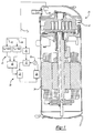
- the sole figure is a schematic view of a circuit for controlling a compressor motor.
- a compressor 20 includes a pump unit 22 driven by a motor 24.
- a motor relay 26 may be deactivated to stop operation of the compressor motor 24 through a safety circuit 28.
- the pump unit 22 is shown as a scroll compressor, but this invention extends to any type of compressor.
- an AC power source 30 is part of the circuit 28 and supplies power to a first switch 32.
- the first switch 32 is preferably a triac receiving an input from AC power source 30, and a second input from a microprocessor 34, as will be described below.
- the output of the triac extends to a second switch 36.
- the switch 36 is preferably a relay which communicates power to the motor relay 26.
- a comparing circuit 40 receives two inputs 42 and 44.
- the input 42 compares a voltage from a pressure sensor V p to the max value. If the V p exceeds the V max value then a signal is sent to an OR gate 45.
- the second input 44 of the circuit compares V p to a minimum value. If the V p value is less than the V minimum, then a second signal is sent to the OR gate 45. If the output of the gate 45 is that either 42 or 44 indicates a problem, then the relay switch 36 opens the relay 26.
- the effect of the combined circuit 40 is to ensure that the V p is at least equal to a minimum value, and is less than a maximum value.
- the V p value is sent also to the microprocessor 34.
- the V value is compared to system condition, and a signal is sent to the triac 26 if the V p value exceeds a predetermined maximum.
- the predetermined maximum by the microprocessor is typically less than the V max value.
- the portion 40 of the circuit is intended as a fail-safe component to ensure that the pressure sensor 50 and the microprocessor based control are operating properly. If the V p value is not within the range of the comparing circuit 40, and yet the microprocessor has not stopped operation of the motor through the triac 32, there is some indication that either the pressure sensor 50 or the microprocessor control itself have failed. Thus, the comparing circuit 40 will operate to stop the compressor.
- the pressure sensor 50 may be as known, and is shown on the output 52 of the compressor pump unit 22. Typically, the pressure sensor senses the pressure and transforms that pressure into a voltage which is relative to the pressure.
- the present invention discloses a low cost effective fail-safe design for incorporating electronic controls into a compressor pressure sensor.
- a worker of ordinary skill in the art would recognize how to provide the particular software and hardware. It is not the design of any one component which is inventive here, but rather the combination of the components to achieve the benefits as set forth in the following claims which is inventive. Moreover, a worker in this art would recognize that there would be many modifications within the scope of this invention. For that reason, the following claims should be studied to determine the true scope and content of this invention.
Landscapes
- Engineering & Computer Science (AREA)
- Mechanical Engineering (AREA)
- General Engineering & Computer Science (AREA)
- Control Of Positive-Displacement Pumps (AREA)
- Applications Or Details Of Rotary Compressors (AREA)
Abstract
Description
Claims (7)
- A compressor (20) comprising:a pump unit (22) ;a motor (24) for driving said pump unit; anda switching circuit (28) for stopping operation of said motor, said switching circuit receiving an electric signal from a pressure sensor (50), said electric signal be operable to stop operation of said compressor motor (24) should a pressure signal be indicative of a pressure higher than a preset maximum.
- A compressor as set forth in Claim 1, wherein said switching circuit includes a switch (32) receiving a signal from a microprocessor (34) that evaluates said electric signal, said switch (32) opening should said electric signal be indicative of an unduly high pressure.
- A compressor as set forth in Claim 2, wherein said switch (32) is a triac switch.
- A compressor as set forth in Claim 2 or 3, wherein a comparing circuit (40) monitors a voltage from said electric signal to ensure that said electric signal is indicative of proper operation of said circuit, and said comparing circuit (40) being operable to open a switch and stop operation of said compressor motor (24) in the event that said voltage from said pressure sensor is indicative of a problem in said system.
- A compressor as set forth in Claim 4, wherein said comparing circuit (40) includes both a maximum and a minimum value for said electric signal, and if either of said minimum or said maximum values are exceeded, said comparing circuit (40) stops operation of said compressor motor (24).
- A compressor as set forth in Claim 4 or 5, wherein said switch communicating with said comparing circuit (40) is a second switch (36).
- A compressor comprising:a pump unit (22);a motor (24) for driving said pump unit; anda switching circuit (28) for stopping operation of said motor, said switching circuit receiving an electric signal from a pressure sensor (50), said electric signal be operable to stop operation of said compressor motor (24) should a pressure signal be indicative of a pressure higher than a preset maximum, said switching circuit including a triac switch (32) receiving a signal from a microprocessor (34), said microprocessor (34) receiving said electric signal, said microprocessor (34) comparing said electric signal to a maximum signal, said microprocessor (34) sending a signal to open said triac switch (32) should said electric signal be indicative of an unduly high pressure, and a comparing circuit (40) being incorporated into said switching circuit (28), said comparing circuit (40) comparing said electric signal to stop operation of said compressor motor (24) if said electric signal is outside of one of said minimum and maximum voltages.
Applications Claiming Priority (2)
| Application Number | Priority Date | Filing Date | Title |
|---|---|---|---|
| US09/742,991 US6497554B2 (en) | 2000-12-20 | 2000-12-20 | Fail safe electronic pressure switch for compressor motor |
| US742991 | 2000-12-20 |
Publications (3)
| Publication Number | Publication Date |
|---|---|
| EP1219836A2 true EP1219836A2 (en) | 2002-07-03 |
| EP1219836A3 EP1219836A3 (en) | 2003-04-02 |
| EP1219836B1 EP1219836B1 (en) | 2006-08-09 |
Family
ID=24987073
Family Applications (1)
| Application Number | Title | Priority Date | Filing Date |
|---|---|---|---|
| EP01310382A Expired - Lifetime EP1219836B1 (en) | 2000-12-20 | 2001-12-12 | Compressor with outlet pressure control |
Country Status (5)
| Country | Link |
|---|---|
| US (1) | US6497554B2 (en) |
| EP (1) | EP1219836B1 (en) |
| JP (1) | JP2002227771A (en) |
| DE (1) | DE60122103T2 (en) |
| DK (1) | DK1219836T3 (en) |
Cited By (2)
| Publication number | Priority date | Publication date | Assignee | Title |
|---|---|---|---|---|
| FR2936844A1 (en) * | 2008-10-02 | 2010-04-09 | Inergy Automotive Systems Res | ROTARY PUMP FOR VEHICLE |
| EP2175135A4 (en) * | 2007-07-31 | 2013-02-27 | Ubukata Ind Co Ltd | HERMETIC ELECTRIC COMPRESSOR |
Families Citing this family (32)
| Publication number | Priority date | Publication date | Assignee | Title |
|---|---|---|---|---|
| US6558126B1 (en) * | 2000-05-01 | 2003-05-06 | Scroll Technologies | Compressor utilizing low volt power tapped from high volt power |
| US7412842B2 (en) | 2004-04-27 | 2008-08-19 | Emerson Climate Technologies, Inc. | Compressor diagnostic and protection system |
| US7275377B2 (en) | 2004-08-11 | 2007-10-02 | Lawrence Kates | Method and apparatus for monitoring refrigerant-cycle systems |
| US7931447B2 (en) | 2006-06-29 | 2011-04-26 | Hayward Industries, Inc. | Drain safety and pump control device |
| US8590325B2 (en) | 2006-07-19 | 2013-11-26 | Emerson Climate Technologies, Inc. | Protection and diagnostic module for a refrigeration system |
| US20080216494A1 (en) | 2006-09-07 | 2008-09-11 | Pham Hung M | Compressor data module |
| JP5005449B2 (en) * | 2007-07-12 | 2012-08-22 | 東芝キヤリア株式会社 | Hermetic compressor, refrigeration cycle equipment |
| US20090037142A1 (en) | 2007-07-30 | 2009-02-05 | Lawrence Kates | Portable method and apparatus for monitoring refrigerant-cycle systems |
| US8393169B2 (en) | 2007-09-19 | 2013-03-12 | Emerson Climate Technologies, Inc. | Refrigeration monitoring system and method |
| US8160827B2 (en) | 2007-11-02 | 2012-04-17 | Emerson Climate Technologies, Inc. | Compressor sensor module |
| US9140728B2 (en) | 2007-11-02 | 2015-09-22 | Emerson Climate Technologies, Inc. | Compressor sensor module |
| US7654804B2 (en) * | 2008-01-08 | 2010-02-02 | Chu Henry C | Fluid displacement apparatus having pressure sensing device |
| EP2442050A1 (en) * | 2009-06-12 | 2012-04-18 | Panasonic Corporation | Refrigeration cycle device |
| WO2011106530A1 (en) | 2010-02-25 | 2011-09-01 | Hayward Industries, Inc. | Universal mount for a variable speed pump drive user interface |
| CA2828740C (en) | 2011-02-28 | 2016-07-05 | Emerson Electric Co. | Residential solutions hvac monitoring and diagnosis |
| US20130121843A1 (en) * | 2011-11-11 | 2013-05-16 | Thermo King Corporation | Compressor digital control failure shutdown algorithm |
| US8964338B2 (en) | 2012-01-11 | 2015-02-24 | Emerson Climate Technologies, Inc. | System and method for compressor motor protection |
| US9480177B2 (en) | 2012-07-27 | 2016-10-25 | Emerson Climate Technologies, Inc. | Compressor protection module |
| US9310439B2 (en) | 2012-09-25 | 2016-04-12 | Emerson Climate Technologies, Inc. | Compressor having a control and diagnostic module |
| CA2904734C (en) | 2013-03-15 | 2018-01-02 | Emerson Electric Co. | Hvac system remote monitoring and diagnosis |
| US9803902B2 (en) | 2013-03-15 | 2017-10-31 | Emerson Climate Technologies, Inc. | System for refrigerant charge verification using two condenser coil temperatures |
| WO2014143779A2 (en) | 2013-03-15 | 2014-09-18 | Hayward Industries, Inc | Modular pool/spa control system |
| US9551504B2 (en) | 2013-03-15 | 2017-01-24 | Emerson Electric Co. | HVAC system remote monitoring and diagnosis |
| AU2014248049B2 (en) | 2013-04-05 | 2018-06-07 | Emerson Climate Technologies, Inc. | Heat-pump system with refrigerant charge diagnostics |
| JP2015038355A (en) * | 2014-10-01 | 2015-02-26 | 三菱重工業株式会社 | Inverter-integrated electric compressor and vehicle air conditioner equipped with the same |
| EP3405629A4 (en) | 2016-01-22 | 2020-01-22 | Hayward Industries, Inc. | SYSTEMS AND METHODS FOR PROVIDING NETWORK CONNECTIVITY AND MONITORING, VALVE ACTUATOR OPTIMIZATION AND REMOTE CONTROL OF POOL AND SPA EQUIPMENT |
| US11720085B2 (en) | 2016-01-22 | 2023-08-08 | Hayward Industries, Inc. | Systems and methods for providing network connectivity and remote monitoring, optimization, and control of pool/spa equipment |
| US10238146B2 (en) | 2016-02-27 | 2019-03-26 | Brandon Nedelman | Hookah vaporizor machine |
| US10718337B2 (en) | 2016-09-22 | 2020-07-21 | Hayward Industries, Inc. | Self-priming dedicated water feature pump |
| JP2020528506A (en) | 2017-03-22 | 2020-09-24 | バレステロス,ジョナサン | Low flow devices for low flow fluid delivery systems and low flow fluid delivery systems |
| US11852131B2 (en) | 2017-09-25 | 2023-12-26 | Carrier Corporation | Pressure safety shutoff |
| US11988421B2 (en) | 2021-05-20 | 2024-05-21 | Carrier Corporation | Heat exchanger for power electronics |
Family Cites Families (12)
| Publication number | Priority date | Publication date | Assignee | Title |
|---|---|---|---|---|
| GB2029513B (en) * | 1978-09-11 | 1982-08-18 | Atc Pneumatics Ltd | Improvements in or relating to control systems for compressors |
| JPS57124090A (en) * | 1981-01-23 | 1982-08-02 | Hitachi Ltd | Rotation control of compressor for air conditioner |
| US4538422A (en) * | 1984-05-14 | 1985-09-03 | Carrier Corporation | Method and control system for limiting compressor capacity in a refrigeration system upon a recycle start |
| US4527953A (en) * | 1984-10-12 | 1985-07-09 | E. I. Du Pont De Nemours And Company | Pump unit for sampling air |
| US4863355A (en) * | 1987-03-20 | 1989-09-05 | Tokico Ltd. | Air compressor having control means to select a continuous or intermittent operation mode |
| FI912940L (en) * | 1991-06-17 | 1992-12-18 | Tamrock Oy | FOERFARANDE OCH ANORDNING FOER STYRNING AV STARTANDE AV SCRUVKOMPRESSOR |
| US5218837A (en) * | 1992-06-26 | 1993-06-15 | Robertshaw Controls Company | Control system for controlling the operation of an air conditioning compressor and method of making the same |
| JP3404990B2 (en) * | 1995-05-17 | 2003-05-12 | 日産自動車株式会社 | Heat pump type air conditioner for vehicles |
| JPH10196577A (en) * | 1997-01-17 | 1998-07-31 | Hitachi Ltd | Oil-cooled screw compressor |
| US6210119B1 (en) * | 1998-06-05 | 2001-04-03 | Carrier Corporation | Reverse rotation detection compressors with a preferential direction of rotation |
| DE19848413B4 (en) * | 1998-10-21 | 2009-06-04 | Pierburg Gmbh | Motor-pump unit |
| US6302654B1 (en) * | 2000-02-29 | 2001-10-16 | Copeland Corporation | Compressor with control and protection system |
-
2000
- 2000-12-20 US US09/742,991 patent/US6497554B2/en not_active Expired - Lifetime
-
2001
- 2001-12-10 JP JP2001375442A patent/JP2002227771A/en active Pending
- 2001-12-12 EP EP01310382A patent/EP1219836B1/en not_active Expired - Lifetime
- 2001-12-12 DK DK01310382T patent/DK1219836T3/en active
- 2001-12-12 DE DE60122103T patent/DE60122103T2/en not_active Expired - Lifetime
Cited By (3)
| Publication number | Priority date | Publication date | Assignee | Title |
|---|---|---|---|---|
| EP2175135A4 (en) * | 2007-07-31 | 2013-02-27 | Ubukata Ind Co Ltd | HERMETIC ELECTRIC COMPRESSOR |
| FR2936844A1 (en) * | 2008-10-02 | 2010-04-09 | Inergy Automotive Systems Res | ROTARY PUMP FOR VEHICLE |
| US9255574B2 (en) | 2008-10-02 | 2016-02-09 | Inergy Automotive Systems Research (Societe Anonyme) | Rotary pump for a vehicle |
Also Published As
| Publication number | Publication date |
|---|---|
| EP1219836A3 (en) | 2003-04-02 |
| EP1219836B1 (en) | 2006-08-09 |
| DE60122103T2 (en) | 2007-04-12 |
| DK1219836T3 (en) | 2006-11-27 |
| US20020076332A1 (en) | 2002-06-20 |
| JP2002227771A (en) | 2002-08-14 |
| DE60122103D1 (en) | 2006-09-21 |
| US6497554B2 (en) | 2002-12-24 |
Similar Documents
| Publication | Publication Date | Title |
|---|---|---|
| US6497554B2 (en) | Fail safe electronic pressure switch for compressor motor | |
| US6238188B1 (en) | Compressor control at voltage and frequency extremes of power supply | |
| US7922457B2 (en) | System and method for controlling a variable speed compressor during stopping | |
| US6568197B2 (en) | Refrigerating unit | |
| US6558126B1 (en) | Compressor utilizing low volt power tapped from high volt power | |
| JP3837278B2 (en) | Compressor operation method | |
| JP2754079B2 (en) | Control method and control device for compressor system | |
| US7481069B2 (en) | Controlling a voltage-to-frequency ratio for a variable speed drive in refrigerant systems | |
| US20070177985A1 (en) | Integral sensor and control for dry run and flow fault protection of a pump | |
| CA2541512A1 (en) | Refrigerant cycle with operating range extension | |
| US7300257B2 (en) | Prevention of unpowered reverse rotation in compressors | |
| KR20070027762A (en) | Valve to prevent non-powered reverse operation when the operation is stopped | |
| US6171064B1 (en) | Reverse rotation detection for scroll compressor utilizing suction temperature | |
| EP0521639B1 (en) | Unloading valve for an air compressor system | |
| WO2022044862A1 (en) | Air compressor | |
| US10724509B2 (en) | Electric control valve for a coolant compressor | |
| JPH01285692A (en) | Control method for screw compressor driven by expansion machine | |
| MXPA06013889A (en) | Pump control. | |
| JP2518114B2 (en) | Compressor drive | |
| JPH03247960A (en) | Degree of overheat control device for compressor | |
| JP4399655B2 (en) | Compressed air production facility | |
| JPH05133346A (en) | Air source device | |
| JPH07208371A (en) | Inverter driven screw compressor | |
| JP3882112B2 (en) | Screw compressor | |
| JP2774433B2 (en) | Centrifugal compressor capacity control device |
Legal Events
| Date | Code | Title | Description |
|---|---|---|---|
| PUAI | Public reference made under article 153(3) epc to a published international application that has entered the european phase |
Free format text: ORIGINAL CODE: 0009012 |
|
| AK | Designated contracting states |
Kind code of ref document: A2 Designated state(s): AT BE CH CY DE DK ES FI FR GB GR IE IT LI LU MC NL PT SE TR |
|
| AX | Request for extension of the european patent |
Free format text: AL;LT;LV;MK;RO;SI |
|
| PUAL | Search report despatched |
Free format text: ORIGINAL CODE: 0009013 |
|
| AK | Designated contracting states |
Kind code of ref document: A3 Designated state(s): AT BE CH CY DE DK ES FI FR GB GR IE IT LI LU MC NL PT SE TR |
|
| AX | Request for extension of the european patent |
Extension state: AL LT LV MK RO SI |
|
| 17P | Request for examination filed |
Effective date: 20030326 |
|
| 17Q | First examination report despatched |
Effective date: 20030618 |
|
| AKX | Designation fees paid |
Designated state(s): BE DE DK FR GB |
|
| GRAP | Despatch of communication of intention to grant a patent |
Free format text: ORIGINAL CODE: EPIDOSNIGR1 |
|
| GRAS | Grant fee paid |
Free format text: ORIGINAL CODE: EPIDOSNIGR3 |
|
| GRAJ | Information related to disapproval of communication of intention to grant by the applicant or resumption of examination proceedings by the epo deleted |
Free format text: ORIGINAL CODE: EPIDOSDIGR1 |
|
| GRAS | Grant fee paid |
Free format text: ORIGINAL CODE: EPIDOSNIGR3 |
|
| GRAP | Despatch of communication of intention to grant a patent |
Free format text: ORIGINAL CODE: EPIDOSNIGR1 |
|
| RIC1 | Information provided on ipc code assigned before grant |
Ipc: F04C 28/06 20060101ALI20060210BHEP Ipc: F04C 18/02 20060101AFI20060210BHEP Ipc: F04C 28/28 20060101ALI20060210BHEP |
|
| GRAS | Grant fee paid |
Free format text: ORIGINAL CODE: EPIDOSNIGR3 |
|
| GRAA | (expected) grant |
Free format text: ORIGINAL CODE: 0009210 |
|
| AK | Designated contracting states |
Kind code of ref document: B1 Designated state(s): BE DE DK FR GB |
|
| REG | Reference to a national code |
Ref country code: GB Ref legal event code: FG4D |
|
| REF | Corresponds to: |
Ref document number: 60122103 Country of ref document: DE Date of ref document: 20060921 Kind code of ref document: P |
|
| REG | Reference to a national code |
Ref country code: DK Ref legal event code: T3 |
|
| RAP2 | Party data changed (patent owner data changed or rights of a patent transferred) |
Owner name: CARRIER CORPORATION |
|
| ET | Fr: translation filed | ||
| PLBE | No opposition filed within time limit |
Free format text: ORIGINAL CODE: 0009261 |
|
| STAA | Information on the status of an ep patent application or granted ep patent |
Free format text: STATUS: NO OPPOSITION FILED WITHIN TIME LIMIT |
|
| 26N | No opposition filed |
Effective date: 20070510 |
|
| PGFP | Annual fee paid to national office [announced via postgrant information from national office to epo] |
Ref country code: BE Payment date: 20071221 Year of fee payment: 7 |
|
| PGFP | Annual fee paid to national office [announced via postgrant information from national office to epo] |
Ref country code: DK Payment date: 20081112 Year of fee payment: 8 |
|
| BERE | Be: lapsed |
Owner name: *CARRIER CORP. Effective date: 20081231 |
|
| PG25 | Lapsed in a contracting state [announced via postgrant information from national office to epo] |
Ref country code: BE Free format text: LAPSE BECAUSE OF NON-PAYMENT OF DUE FEES Effective date: 20081231 |
|
| REG | Reference to a national code |
Ref country code: DK Ref legal event code: EBP |
|
| PG25 | Lapsed in a contracting state [announced via postgrant information from national office to epo] |
Ref country code: DK Free format text: LAPSE BECAUSE OF NON-PAYMENT OF DUE FEES Effective date: 20100104 |
|
| PGFP | Annual fee paid to national office [announced via postgrant information from national office to epo] |
Ref country code: DE Payment date: 20141209 Year of fee payment: 14 Ref country code: GB Payment date: 20141210 Year of fee payment: 14 |
|
| PGFP | Annual fee paid to national office [announced via postgrant information from national office to epo] |
Ref country code: FR Payment date: 20141208 Year of fee payment: 14 |
|
| REG | Reference to a national code |
Ref country code: DE Ref legal event code: R119 Ref document number: 60122103 Country of ref document: DE |
|
| GBPC | Gb: european patent ceased through non-payment of renewal fee |
Effective date: 20151212 |
|
| REG | Reference to a national code |
Ref country code: FR Ref legal event code: ST Effective date: 20160831 |
|
| PG25 | Lapsed in a contracting state [announced via postgrant information from national office to epo] |
Ref country code: DE Free format text: LAPSE BECAUSE OF NON-PAYMENT OF DUE FEES Effective date: 20160701 Ref country code: GB Free format text: LAPSE BECAUSE OF NON-PAYMENT OF DUE FEES Effective date: 20151212 |
|
| PG25 | Lapsed in a contracting state [announced via postgrant information from national office to epo] |
Ref country code: FR Free format text: LAPSE BECAUSE OF NON-PAYMENT OF DUE FEES Effective date: 20151231 |