EP1219672A1 - Thermoplastic resin foam and process for producing the same - Google Patents
Thermoplastic resin foam and process for producing the same Download PDFInfo
- Publication number
- EP1219672A1 EP1219672A1 EP00951894A EP00951894A EP1219672A1 EP 1219672 A1 EP1219672 A1 EP 1219672A1 EP 00951894 A EP00951894 A EP 00951894A EP 00951894 A EP00951894 A EP 00951894A EP 1219672 A1 EP1219672 A1 EP 1219672A1
- Authority
- EP
- European Patent Office
- Prior art keywords
- layered silicate
- thermoplastic resin
- foam
- chemical substance
- thermoplastic
- Prior art date
- Legal status (The legal status is an assumption and is not a legal conclusion. Google has not performed a legal analysis and makes no representation as to the accuracy of the status listed.)
- Granted
Links
Images

Classifications
-
- C—CHEMISTRY; METALLURGY
- C04—CEMENTS; CONCRETE; ARTIFICIAL STONE; CERAMICS; REFRACTORIES
- C04B—LIME, MAGNESIA; SLAG; CEMENTS; COMPOSITIONS THEREOF, e.g. MORTARS, CONCRETE OR LIKE BUILDING MATERIALS; ARTIFICIAL STONE; CERAMICS; REFRACTORIES; TREATMENT OF NATURAL STONE
- C04B20/00—Use of materials as fillers for mortars, concrete or artificial stone according to more than one of groups C04B14/00 - C04B18/00 and characterised by shape or grain distribution; Treatment of materials according to more than one of the groups C04B14/00 - C04B18/00 specially adapted to enhance their filling properties in mortars, concrete or artificial stone; Expanding or defibrillating materials
- C04B20/0016—Granular materials, e.g. microballoons
- C04B20/002—Hollow or porous granular materials
- C04B20/0024—Hollow or porous granular materials expanded in situ, i.e. the material is expanded or made hollow after primary shaping of the mortar, concrete or artificial stone mixture
-
- C—CHEMISTRY; METALLURGY
- C04—CEMENTS; CONCRETE; ARTIFICIAL STONE; CERAMICS; REFRACTORIES
- C04B—LIME, MAGNESIA; SLAG; CEMENTS; COMPOSITIONS THEREOF, e.g. MORTARS, CONCRETE OR LIKE BUILDING MATERIALS; ARTIFICIAL STONE; CERAMICS; REFRACTORIES; TREATMENT OF NATURAL STONE
- C04B26/00—Compositions of mortars, concrete or artificial stone, containing only organic binders, e.g. polymer or resin concrete
- C04B26/02—Macromolecular compounds
- C04B26/04—Macromolecular compounds obtained by reactions only involving carbon-to-carbon unsaturated bonds
- C04B26/045—Polyalkenes
-
- C—CHEMISTRY; METALLURGY
- C08—ORGANIC MACROMOLECULAR COMPOUNDS; THEIR PREPARATION OR CHEMICAL WORKING-UP; COMPOSITIONS BASED THEREON
- C08J—WORKING-UP; GENERAL PROCESSES OF COMPOUNDING; AFTER-TREATMENT NOT COVERED BY SUBCLASSES C08B, C08C, C08F, C08G or C08H
- C08J9/00—Working-up of macromolecular substances to porous or cellular articles or materials; After-treatment thereof
- C08J9/0066—Use of inorganic compounding ingredients
-
- C—CHEMISTRY; METALLURGY
- C08—ORGANIC MACROMOLECULAR COMPOUNDS; THEIR PREPARATION OR CHEMICAL WORKING-UP; COMPOSITIONS BASED THEREON
- C08J—WORKING-UP; GENERAL PROCESSES OF COMPOUNDING; AFTER-TREATMENT NOT COVERED BY SUBCLASSES C08B, C08C, C08F, C08G or C08H
- C08J9/00—Working-up of macromolecular substances to porous or cellular articles or materials; After-treatment thereof
- C08J9/04—Working-up of macromolecular substances to porous or cellular articles or materials; After-treatment thereof using blowing gases generated by a previously added blowing agent
Definitions
- the present invention relates to a thermoplastic foam which contains a thermoplastic resin and a layered silicate and has uniformly fine foam cells evenly distributed therein and also to a method for production thereof.
- thermoplastic resins Dispersion of a layer silicate in thermoplastic resins is known to improve their mechanical, thermal, gas barrier or other properties.
- layered silicate constituting clay minerals extremely fine, flaky crystals are held together by ionic bonding.
- thermoplastic reins can be improved by disintegrating this aggregate structure by a chemical or physical means to thereby evenly disperse the flaky crystals throughout the thermoplastic resins.
- Japanese Patent Publication No. Hei 8-22946 discloses that a polyamide resin structure containing evenly-dispersed flakes of a layered silicate can be formed by intercalating aminocarboxylic acid into the layered silicate to initially enlarge spacings between adjacent layers, then inserting ⁇ -caprolactam, which is a monomeric moiety of polyamide, into interlayer spaces and concurrently allowing it to undergo polycondensation.
- Japanese Patent Laying-Open No. Hei 9-183910 discloses a method for dispersing a layered silicate in a polymer by mixing, in a molten state, an organic dispersion incorporating an organically-modified layered silicate swelled and dispersed therein with a vinyl polymer compound.
- Japanese Patent Laying-Open No. Hei 9-183910 discloses a method for dispersing a layered silicate in a polymer by mixing, in a molten state, an organic dispersion incorporating an organically-modified layered silicate swelled and dispersed therein with a vinyl polymer compound.
- Hei 10-182892 discloses that melt neading of an organically-modified layered silicate, a polyolefin oligomer containing a hydrogen-linkable functional group and a polyolefin polymer results in the preparation of a polyolefinic resin composite material in which a spacing between adjacent layers of the layered silicate is infinitely swelled in the polymer.
- Japanese Patent Laying-Open No. Hei 8-143697 discloses that a polypropylene foam composition if including a layered silicate with a blowing agent adsorbed therein provides a polypropylene foam with a high expansion ratio and high strength.
- a specific blowing agent must be held adsorbed to the layered silicate. The requirement of a multi-stage treatment thus reduces productivity.
- the use of a silane coupling agent is essential. This increases the cost. The unstable nature of the silane coupling agent which is highly linkable to a moisture in the air reduces handleability.
- the present invention is directed to provide a thermoplastic foam which comprises a thermoplastic resin and a layered silicate and in which foam cells and layered silicate are evenly and finely dispersed, and also to provide a method for production thereof.
- thermoplastic foam which is characterized as containing, as main components, 100 parts by weight of a thermoplastic resin and 0.1 - 50 parts by weight of a layered silicate.
- the layered silicate in the thermoplastic foam has an average interlayer spacing of over 60 ⁇ when determined by X-ray diffractometry.
- X/(Y - 1) 1/3 does not exceed 30 ( ⁇ m), where X ( ⁇ m) is an average cell diameter and Y is an expansion ratio.
- a polyolefin resin is used for the theremoplastic resin.
- At least one selected from smectite clay minerals and micas is used for the layered silicate.
- At least one selected from the group consisting of polyethylene, ethylene- ⁇ -olefin copolymer, ethylene-propylene copolymer, polypropylene and propylene- ⁇ -olefin copolymer is used for the polyolefin resin.
- the method includes the steps of impregnating a volume-expansible chemical substance into interlayer spaces of a layered silicate in a composite material which contains 100 parts by weight of a thermoplastic resin and 0.1 - 50 parts by weight of the layered silicate, and allowing the chemical substance to expand in volume within the composite material for formation of cells therein so that a thermoplastic foam is obtained.
- the step of impregnating the chemical substance is performed by impregnating, under a high pressure, the chemical substance that assumes a gaseous form at ordinary temperature and pressure. Also, the expansion in volume of the chemical substance is effected by vaporizing it within the composite material.
- the chemical substance that assumes a gaseous form at ordinary temperature and pressure is in its supercritical state impregnated into the composite material.
- a method for production of a thermoplastic foam which is characterized as including the steps of preparing a composite material which comprises 100 parts by weight of a thermoplastic resin and 0.1 - 50 parts by weight of a layered silicate that contains a heat decomposable blowing agent between its layers, and heating the composite material to a temperature sufficiently high to cause decomposition of the blowing agent so that a cell structure is formed.
- the method including the steps of impregnating an expansible chemical substance into a thermoplastic resin composition which contains 100 parts by weight of a thermoplastic resin and 0.1 - 50 parts by weight of a layered silicate under a high pressure within an injection molding machine having a cavity and, subsequent to injection of the thermoplastic resin composition impregnated with the chemical substance into the cavity of the injection molding machine, allowing the cavity to enlarge.
- the chemical substance that assumes a gaseous form at ordinary temperature and pressure is in its supercritical state impregnated into the thermoplastic resin composition within the injection molding machine.
- the layered silicate is preferably treated so as to render its interlayer spaces hydrophobic.
- a fine cell structure can be readily formed by allowing the chemical substance present in the interlayer spaces of the layered silicate to expand in volume within a resin so that flaky crystals of the layered silicate are evenly dispersed in an organic polymer.
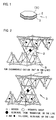
- flaky crystals 2, 3 of a layered silicate 1, e.g., montmorillonite shown in Figure 1 are generally constituted by tetrahedrons with four oxygen ions arranged to surround a central silicon or other ion, octahedrons with six oxygen ions arranged to surround a central aluminum or other ion, and OH groups.
- a sodium, calcium or other cation arranged on a crystal surface (B) binds such flaky crystals 2, 3 by ionic bonding.
- the sodium, calucium or other ion on the crystal surface (B) is generally ion-exchangeable with a cationic material, the insertion of various cationic materials into interlayer spaces is enabled. Utilizing this nature, the above-identified ion can be ion-exchanged with a cationic surfactant.
- the use of a highly nonpolar cationic species for the cationic surfactant lowers the polarity of the layered silicate (B) to thereby facilitate dispersion of the layered silicate in a nonpolar polymer.
- the flaky crystals 2, 3 must be spaced away from each other by applying to interlayer spaces such an energy that counteracts or lowers an electrical interaction between the crystal surfaces (B) .
- the present invention involves subjecting a composite material comprising a thermoplastic resin and a layered silicate to a treatment whereby a volume-expansible chemical substance is inserted into the interlayer spaces of the layered silicate, or alternatively, a heat decomposable substance is incorporated in the interlayer spaces of the layered silicate.
- a volume-expansible chemical substance is inserted into the interlayer spaces of the layered silicate, or alternatively, a heat decomposable substance is incorporated in the interlayer spaces of the layered silicate.
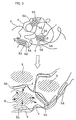
- the subsequent expansion in volume of the chemical substance or thermal decomposition of the heat decomposable blowing agent provides an energy sufficient to separate the flaky crystals from each other.
- the flaky crystals 5A act as barriers, as schematically shown in Figure 3. This suppresses excessive diffusion of the gas through molecular chains 4 of the thermoplastic resin. As a consequence, a foam is obtained including foam cells 6 finely and evenly dispersed therein. The suppression of excessive diffusion of the gas results in the reduced occurrnece of gas escaping. A higher expansion ratio can be obtained as a consequence.
- the thermoplastic foam in accordance with the present invention has an expansion ratio Y in the range of 1.01 - 100.
- an average cell diameter X ( ⁇ m) of the thermoplastic foam preferably satisfies the following relationship (1).
- thermoplastic foam If a numerical value calculated from a left side of the relationship (1) exceeds 30, the reduction in physical properties of the thermoplastic foam, such as in insulation performance, compressive strength or bending creep, may result.
- the layered silicate refers to a silicate mineral which has plural layers comprised of a number of fine flaky crystals and incorporates exchangeable cations between its layers.
- the flaky crystal generally has a thickness of about 1 nm and a ratio (hereinafter referred to as an aspect ratio) of a major diameter to the thickness in the approximate range of 20 - 200.
- these fine flaky crystals are held together by ionic bonding.
- layered silicate incorporating exchangeable cations between its layers is not particularly specified in type.
- layered silicates include smectite clay minerals such as montmorillonite, saponite, hectorite, beidellite, stevensite and nontronite; natural micas such as vermiculite and halloysite; synthetic micas such as swelling mica (swelling mica); and the like.
- layered silicates either synthetic or natural, can be suitably used.
- the use of swelling smectite clay minerals and swelling micas are preferred.
- the above-listed layered silicates may be used alone or in combination.
- the babble growth and gas escaping are suppressed by the barrier action of the flaky crystals of the layered silicate.
- the use of the layered silicate which includes agglomerates of high-aspect ratio flaky crystals thus results in the formation of a fine foam cell structure with a high expansion ratio.
- the use of the layered silicate having flaky crystals with an aspect ratio of 100 or above is preferred.
- the use of montmorillonite including flaky crystals with an aspect ratio of about 100 or above, or. swelling mica including flaky crystals with an aspect ratio of about 150 is more preferred.
- the interlayer spaces of the layered silicate are rendered hydrophobic.
- a nonpolar resin such as a polyolefin resin
- the following techniques (1) - (3) can be utilized to hydrophobicize the interlayer spaces.
- the hydrophobicized layered silicate is suitably used because it shows the increased dispersion in a nonpolar or low-polarity resin such as a polyolefin resin than before being hydrophobicized.
- the cationic surfactant is not particularly specified in type and may be selected from generally-used cationic surfactants.
- cationic surfactants include those comprised chiefly of quaternary ammonium salts, quaternary phosphonium salts and the like.
- the use of quaternary ammonium salts having an alkyl chain with 8 or more carbon atoms is preferred. Without the inclusion of an alkyl chain of 8 or more carbon atoms, the strong hydrophilicity of alkyl ammonium ions may prevent the interlayer spaces of the layered silicate from being rendered nonpolar or less polar to a sufficient extent.
- quaternary ammonium salts include lauryl trimethyl ammonium salt, stearyl trimethyl ammonium salt, trioctyl ammonium salt, distearyl dimethyl ammonium salt, di-cured tallow dimethyl ammonium, distearyl dibenzyl ammonium salt and the like.
- the cation exchange capacity of the layered silicate is preferably 50 - 200 milliequivalents/100 g. If it is excessively low, a smaller amount of a cationic surfactant may be intercalated, via ion exchange, between crystal layers to possibly result in the insufficient hydrophobicization of the interlayer spaces. On the other hand, if it is excessively high, the adjacent layers of the layered silicate may be bound more tightly to each other to result in the difficulty to delaminate (separate) crystal flakes.
- the flaky crystals of the layered silicate serve as barriers to suppress growth of bubbles during evolution thereof. Accordingly, the excessive low loading of the layered silicate may result in the failure to obtain a foam having a fine foam cell structure. The excessive high loading thereof may result in the reduced bending strength and the increased production cost.
- the layered silicate is preferably loaded in the range of 0.1-50 parts by weight, more preferably in the range of 2 - 10 parts by weight, based on 100 parts by weight of the thermoplastic resin.
- the layered silicate when dispersed in the thermoplastic resin preferably has an average interlayer spacing (interlayer distance of a (001) plane of the layered silicate when determined by X-ray diffractometry) of over 60 ⁇ .
- thermoplastic resin The type of the thermoplastic resin is not particularly specified.
- the preferred examples of useful thermoplastic resins include polyolefin resins, EVA resins, polystyrene resins, vinyl chloride resins, ABS resins, polyvinyl butyral resins and various rubbers.
- the use of crystalline resins such as polyolefin resins is more preferred.
- the crystalline resin in an unmolten state shows a high shape-retaining effect.
- the crystalline resin is thus easier to retain a shape of a foam during expansion in volume of the below-stated chemical substance in a composite material comprising the thermoplastic resin and the layered silicate.
- the polyolefin resin for use in the present invention is not particularly specified in type, examples of which include a homopolymer of ethylene, propylene or ⁇ -olefin; a copolymer of ethylene and propylene, a copolymer of ethylene and ⁇ -olefin, a compolymer of propylene and ⁇ -olefin, a copolymer of two or more ⁇ -olefins and the like.
- ⁇ -olefins include 1-butene, 1-pentene, 1-hexene, 4-methyl-1-pentene, 1-heptene, 1-octene and the like.
- polyolefin resins may be used alone or in any combination thereof.
- the molecular weight and molecular weigh distribution of the polyolefin resin is not particularly specified. Its weight average molecular weight is preferably in the range of 5,000 - 5,000,000, more preferably in the range of 20,000 - 300,000. Its molecular weight distribution (weight average molecular weight Mw / number average molecular weight Mn) is preferably in the range of 2 - 80, more preferably in the range of 3 - 40.
- polymer compounds may be alloyed or blended with the thermoplastic resin.
- a polymer compound incorporating a grafted maleic or other carboxylic acid may be added in a small amount to increase in advance an affinity between the thermoplastic resin and the layered silicate.
- suitable additives may be added to the polyolefinic resin to impart desired physical properties thereto.
- suitable additives include an antioxidant, light stabilizer, UV absorber, lubricant, flame retardant antistatic agent and the like.
- a substance serviceable as a crystal nucleating agent can also be added in a small amount to finely divide crystals so that the uniformity of physical properties is enhanced.
- thermoplastic resin is a crystalline resin
- any arbitrary organic or inorganic gas which exists in a gaseous state within the range from (melting point - 20 °C) to (melting point + 20 °C) can be used as the chemical substance for insertion into the interlayer spaces of the layered silicate used.
- thermoplastic resin is a noncrystalline resin
- any arbitrary organic or inorganic gas which exists in a gaseous state within the range from (glass transition point - 20 °C) to (glass transition point + 20 °C) can be used as the chemical substance for insertion into the interlayer spaces of the layered silicate used.
- gases examples include carbon dioxide (carbonic acid gas), nitrogen, oxygen, argon or water; organic gases such as flon, low-molecular weight hydrocarbons, chlorinated aliphatic hydrocarbons, alcohols, benzene, toluene, xylene, mesitylene; or the like.
- a gas is suitably used which assumes a gaseous form at ordinary temperature (23 °C) and pressure (atmospheric pressure).
- low-molecular weight hydrocarbons examples include pentane, butane and hexane.
- chlorinated aliphatic hydrocarbons include methyl chloride and methylene chloride. Also useful are various fluorinated aliphatic hydrocarbons.
- Carbon dioxide is suitable for use as the chemical substance because it eliminates the need of gas recovery and is safe to handle.
- Carbon dioxide can be changed to a supercritical state at relatively low temperature and pressure and, while in the form of a supercritical fluid, acts in an effective manner to promote dispersion of the layered silicate.
- the supercritical state refers to a state in which temperature and pressure are above a critical point of the chemical substance to be impregnated. In the supercritical state, the chemical substance has no vapor-liquid transition.
- the supercritical fluid exhibits properties intermediate between the gas and the liquid, such as a high thermal conductivity, low diffusion rate and low viscosity. Accordingly, the supercritical fluid is suited in dispersing the layered silicate.
- the chemical substance may take a liquid form at ordinary temperature.
- Examples of such chemical substances include saturated hydrocarbons such as pentane, neopentane, hexane and heptane; chlorine compounds such as methylene chloride, trichloroethylene and dichloroethane; and fluorine compounds such as CFC-11, CFC-12, CFC-13 and CFC-141b.
- An illustrative technique involves introducing, in the form of a gas, the chemical substance in a closed autoclave for subsequent pressurizing. Using this technique, the pressure and temperature can be readily controlled.
- thermoplastic resin in a melt extruder with a vented screw and supplying the gas from a middle portion of a cylinder to a vent portion.
- the chemical substance can be impregnated in a more effective manner into the composite material containing the thermoplastic resin and the layered silicate to insure continuous production of thermoplastic foams.
- such a gas is preferably maintained at a pressure of 9.8 x 10 5 Pa or above, more preferably 9.8 x 10 6 Pa or above.
- the conditions required to change the gas that assumes a gaseous form at ordinary temperature and pressure, as the chemical substance, to a supercritical fluid vary depending upon the type of the chemical substance used. As described above, carbon dioxide shows a supercritical property under relatively gentle conditions and can be changed to a supercritical fluid at 60 °C and 60 atmospheric pressure, for example.
- thermoplastic resin and layered silicate No particular limitation is given to the temperature at which the chemical substance is impregnated into the composite material containing the thermoplastic resin and layered silicate, unless it causes deterioration of the composite material.
- a larger amount of the chemical substance dissolves in the composite material containing the thermoplastic resin and layered silicate to result in obtaining a higher expansion ratio. Accordingly, the higher impregnation temperature is preferred.
- the temperature is maintained within the range from (melting point - 20 °C) to (melting point + 20 °C), if a crystalline resin is used for the thermoplastic resin, or within the range from (glass transition point - 20 °C) to (glass transition point + 20 °C) if a noncrystalline resin is used for the thermoplastic resin.
- the impregnation temperature of the chemical substance is higher than (melting or glass transition point + 20 °C)
- a molecular motion of the thermoplastic resin becomes active to result in the increased tendency of the chemical substance once dissolved in the composite material to escape therefrom.
- the impregnation temperature of the chemical substance is lower than the melting or glass transition point, the molecular motion of the thermoplastic resin becomes insufficient and in some cases prevents the sufficient dissolution of the chemical substance in the composite material.
- thermoplastic foam in accordance with the present invention is produced by impregnating the aforementioned chemical substance into the composite material containing the thermoplastic resin and the layered silicate and then allowing the chemical substance to expand in the composite material.
- the technique used to effect expansion in volume of the chemical substance is suitably chosen depending upon the type of the chemical substance used, and may comprise impregnating the chemical substance in the form of a gas into the composite material under a relative high pressure, and then reducing the pressure or applying heat.
- the temperature at which the chemical substance is caused to expand in volume within the composite material is not particularly specified.
- the temperature is maintained within the range from (melting point - 50 °C) to (melting point + 10 °C) if the thermoplastic resin is a crystalline resin or within the range from (glass transition point - 50 °C) to (glass transition point + 50 °C) if the thermoplastic resin is a noncrystalline resin. That is, if the temperature of volume expansion is higher than (melting point + 10 °C) or (glass transition point + 50 °C), the gas once dissolved is allowed to escape readily, resulting in the difficulty to sustain a desired cell structure. On the other hand, if the temperature of volume expansion is below (melting or glass transition point - 50 °C), a molecular motion of the thermoplastic resin is restricted to result in the failure to obtain a high expansion ratio.
- a foam structure is obtained by impregnating a chemical substance that assumes a gaseous form at ordinary temperature and pressure into a thermoplastic resin composition containing 100 parts by weight of a thermoplastic resin and 0.1 - 50 parts by weight of a layered silicate under a high pressure within an injection molding machine having a cavity, injecting the thermoplastic resin composition impregnated with the chemical substance into the cavity of the injection molding machine, and then enlarging the cavity.
- thermoplastic resins, layered silicates and gases that assume a gaseous form at ordinary temperature and pressure were previously listed.
- the use of carbon dioxide is preferred because it eliminates the need of gas recovery and is safe to handle.
- thermoplastic resin composition impregnated with the chemical substance is injected into the mold cavity of the injection molding machine, followed by enlargement of the cavity.
- the cavity is enlarged in a direction perpendicular to a parting plane of an injection mold by simply moving a moveable mold half backward.
- the cavity may be enlarged in a direction parallel to the parting plane as by using a slide core, if the occasion permits.
- the size of the cavity after being enlarged is suitably adjusted depending upon the desired expansion ratio of the end foam. If the size is excessively small, the enlargement results in the failure to impart properties (light weight, heat insulating or other properties) needed for foams. On the other hand, if the size is excessively large, the cavity after enlargement may be insufficiently filled with the thermoplastic resin composition to result in the failure to impart the desired expansion ratio and shape of the end foam. Accordingly, the cavity is preferably enlarged to 2-30 times of its size before being enlarged.
- the time required to enlarge the cavity may be varied depending upon the desired expansion ratio and shape of the resulting foam and upon the particular tensile viscosity of the thermoplastic resin composition used.
- the means for enlarging the cavity has its limit, a shorter operation thereof is preferred. This permits expansion of the chemical substance while having a high tensile viscosity and prevents cell breakage, so that a foam having a fine cell structure can be obtained. It is accordingly preferred that the enlargement completes within 0.5 - 5 seconds.
- the chemical substance is brought to a supercritical state when its impregnation is carried out within the injection molding machine. This further promotes dispersion of the flaky crystals of the layered silicate.
- the thermoplastic resin composition impregnated with the chemical substance is first injected into the cavity.
- the pressure within the cavity is rapidly released.
- This provides an energy sufficient to overcome an electrical attraction force between the layered silicates.
- the flaky crystals of the layered silicate can be separated from each other.
- the subsequent enlargement of the cavity causes the chemical substance to undergo a rapid change to a gaseous state.
- the change of the chemical substance from the supercritical state to the gaseous state is accompanied by rapid and large volume expansion. This provides an energy sufficient to separate the flaky crystals of the layered silicate and thus further promotes dispersion of the flaky crystals.
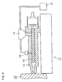
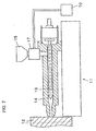
- Figure 4 is a sectional view, illustrating one example of an injection molding machine for use in this embodiment.
- reference numerals 11, 12 and 16 represent an injection molding machine, an injection mold and a vent portion, respectively.
- the injection molding machine for use in this embodiment includes an injection machine main body 11 and an injection mold 12.
- the injection machine main body 11 includes a cylinder 14 with a built-in screw 13, a hopper 15 through which the thermoplastic resin composition is fed into the cylinder 14, and a vent portion 16 through which the chemical substance from a gas forcing device 61 is introduced into the cylinder 14.
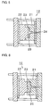
- Figure 5 is a sectional view, showing the injection mold, for use in this embodiment, in the condition of being closed by clamping.
- Figure 6 is a sectional view, showing an injection mold cavity in the condition of being enlarged.
- reference numerals 12 and 23 denote an injection mold and a mold cavity, respectively.
- the injection mold for use in this embodiment includes a stationary mold half 21 and a movable mold half 22.
- the cavity 23 is defined between the stationary half 21 and the movable half 22.
- thermoplastic resin composition is fed into the hopper 15 shown in Figure 4, and the chemical substance that assumes a gaseous form at ordinary temperature and pressure is introduced by the gas forcing device 61 into the cylinder 14 through the vent portion 16.
- thermoplastic resin composition An interior pressure of the cylinder is now increased. Also, the chemical substance is impregnated into the thermoplastic resin composition at a temperature and pressure sufficient to bring the chemical substance to a supercritical state.
- thermoplastic resin composition while in a molten state is pressure sealed, the chemical substance while pressurized or in a supercritical state can be impregnated into the thermoplastic resin composition more effectively.
- thermoplastic resin composition 25 impregnated with the chemical substance is then injected into the cavity 23 through a sprue 24 of the injection mold 12.
- thermoplastic resin composition injected into the cavity 23 to result in obtaining a thermoplastic foam.
- Figure 7 Figure 4 is a sectional view, illustrating another example of an injection molding machine for use in this embodiment.
- reference numeral 17 denotes an airtight container.
- an injection machine main body 11 includes a cylinder 14 with a built-in screw 13, a hopper 15 through which the thermoplastic resin composition is fed into the cylinder 14, and the airtight container 17 through which the chemical substance from a gas forcing device 70 is introduced into the cylinder 14.
- thermoplastic resin composition is fed into the hopper 15 of the injection machine main body 11 shown in Figure 7. Then, the chemical substance that takes a gaseous form at ordinary temperature and pressure is forced by the gas forcing device 70 into the airtight container 17, impregnated into the thermoplastic resin composition fed into the hopper 15 either under a high pressure or at a temperature and pressure sufficient to bring the chemical substance to a supercritical state, and injected into the cylinder 14.
- thermoplastic foam can be obtained.
- thermoplastic foam is obtained by preparing a composite material which comprises 100 parts by weight of a thermoplastic resin and 0.1 - 50 parts by weight of a layered silicate containing a heat decomposable blowing agent between its layers, and heating the composite material to a temperature sufficiently high to cause decomposition of the blowing agent.
- a composite material which comprises 100 parts by weight of a thermoplastic resin and 0.1 - 50 parts by weight of a layered silicate containing a heat decomposable blowing agent between its layers, and heating the composite material to a temperature sufficiently high to cause decomposition of the blowing agent.
- the heat decomposable blowing agent refers to a substance which decomposes when heated to generate a gas.
- examples of such substances include azodicarbonamide, benzene sulfonyl hydrazide, dinitrosopentamethylenetetramine, toluene sulfonyl hydrazide, 4,4-oxybis(benzene sulfonyl hydrazide) and the like.
- the technique used to incorporate the heat decomposable blowing agent into the interlayer spaces of the layered silicate is not particularly specified.
- the following techniques can be employed, for example.
- the heat decomposable blowing agent may be incorporated in the interlayer spaces of the layered silicate at any temperature which neither causes deterioration of the composite material nor initiates decomposition of the blowing agent.
- the temperature at which the heat decomposable blowing agent is caused to expand in the thermoplastic resin is not particularly specified.
- thermoplastic foam obtained in accordance with the present invention has uniform and fine foam cells as a result of the barrier action of the flaky crystals of the layered silicate. Accordingly, the thermoplastic foam in accordance with the present invention is applicable for various uses. Depending upon the purposes contemplated, suitable changes and modifications may be made to the thermoplastic foam in accordance with the present invention. For example, its expansion ratio is not necessarily required to be high when it is applied for uses where high foam properties are not necessarily required or a reinforcing effect as a result of dispersion of the layered silicate is mainly sought.
- the thermoplastic foam in accordance with the present invention may be heated or pressed to break cells to use as a solid body. Also, the thermoplastic foam obtained in accordance with the present invention may be used as a master batch for provision in the succeeding fabrication process.
- the following minerals were used for the layered silicate.
- thermoplastic resin For the increased affinity between the thermoplastic resin and the layered silicate and also for comparison with conventional cases, the following acid-modified polyolefin resins were used.
- thermoplastic resin and a layered silicate in the weight ratio specified in Table 1 were supplied to an interior of a Labo Plastomill, manufactured by Toyo Seiki Ltd., in which they were melt kneaded at a temperature set at 170 °C.
- the layered silicate was selected from those described above as either excluding or containing a cationic surfactant.
- the above-described acid-modified polyolefin resin was further added in the proportion specified in Table 1, based on 100 parts by weight of the thermoplastic resin, for the purpose of improving an affinity between the thermoplastic resin and the layered silicate.
- the resulting composite composition was preheated in a melt press at 170 °C for 5 minutes and then pressed at a pressure of 9.8 MPa for 1 minute to provide a 1 mm thick sheet.
- a 3 cm square piece was cut out from the sheet and placed in an closed autoclave.
- An interior temperature of the autoclave was controlled at a temperature 10 °C higher than a melting point or glass transition point of the thermoplastic resin.
- a pressurized carbonic acid gas, nitrogen or water vapor was introduced into the autoclave.
- the interior pressure of the autoclave was kept at 1.67 MPa for 30 minutes.
- the interior temperature of the autoclave was set at a level 10 °C lower than the melting or glass transition point of the thermoplastic resin. In this condition, the gas present in the autoclave was rapidly discharged therefrom to return the interior pressure of the autoclave to an ordinary pressure. This resulted in obtaining sample foams.
- thermoplastic resin and the layered silicate specified in type in Table 1 were supplied in the weight proportion also specified in Table 3 to an interior of a Labo Plastomill, manufactured by Toyo Seiki Ltd., in which they were melt kneaded at a temperature set at 170 °C.
- a Labo Plastomill manufactured by Toyo Seiki Ltd., in which they were melt kneaded at a temperature set at 170 °C.
- montmorillonite or swelling mica which contains azodicarbonamide between layers was used.
- Example 19 - 23 and Comparative Examples 8 and 9 the acid-modified polyolefin resin was further added in the proportion specified in Table 3, based on 100 parts by weight of the thermoplastic resin, for the purpose of improving an affinity between the thermoplastic resin and the layered silicate.
- the resulting composite composition was preheated in a melt press at 170 °C for 5 minutes and then pressed at a pressure of 9.8 MPa for 1 minute to provide a 1 mm thick sheet. This sheet was immersed in a hot silicone oil kept at 200 °C for 10 seconds to obtain a foam.
- thermoplastic resin and layered silicate containing no heat decomposable blowing agent between layers were supplied in the weight ratio specified in Table 3 to an interior of a Labo Plastomill, manufactured by Toyo Seiki Ltd., in which they were melt kneaded at a temperature set at 200 °C.
- Comparative Example 8 5 parts by weight of the acid-modified polyolefin was also added, based on 100 parts by weight of the thermoplastic resin, to increase an affinity between the thermoplastic resin and the layered silicate.
- compositions were used for the composite composition of a solvent-swollen layered silicate and a thermoplastic resin.
- 500 g of DSDM-modified montmorillonite manufactured by Hojun Kogyo Co., Ltd. (product name: New S-Ben D) was added to 5 L xylene (product of Wako Pure Chem. Ind., Ltd.).
- xylene product of Wako Pure Chem. Ind., Ltd.
- the slurry was introduced from a liquid delivery nozzle disposed along the extrusion line and the xylene was suctioned from a vent port located downstream of the liquid delivery nozzle along the extrusion line.
- the composite material was extruded from a sheet die attached to a front end of the extruder into a 1 mm thick sheet serving as a sample for subsequent evaluation.
- a Hojun Kogyo DSDM-modified montmorillonite product name: New S-Ben D
- the resulting composite composition was preheated in a melt press at 200 °C for 5 minutes and then pressed at a pressure of 9.8 MPa for 1 minute to provide a 1 mm thick sheet serving as a sample for evaluation.
- a sum of proportions of the blowing agent and silane coupling agent that respectively adsorbed to the layered silicate was 45.3 %.
- An X-ray diffractometer (product of Rigaku Co., Ltd., product name: RINT-1100) was used to measure a diffraction peak 2 ⁇ for layered planes of the layered silicate in the composite material.
- a secondary electron reflection type electron microscope (product of JOEL Ltd., product name: JSM-5800LV) was utilized to observe the foam. 50 foam cells were observed for cell diameter and an arithmetic mean thereof was taken as a foam cell diameter of the foam.
- Examples 1 - 24 expansion of the chemical substance impregnated in the composite material containing the layered silicate resulted in obtaining foams having a high expansion ratio and a uniform cell diameter. Also, either foam has a foam cell diameter within the range of 10 - 75 ⁇ m, which value is very small for a high expansion-ratio foam.
- Comparative Example 14 Japanese Patent Laying-Open No. Hei 8-143697
- a high expansion ratio provided an average interlayer spacing of 28 ⁇ and a very large foam cell diameter of 402 ⁇ m. This is considered due to the uneven dispersion of the layered silicate that led to the insufficient suppression of diffusion of the gas.
- the raw material used in the present invention is below described.
- the following minerals were used for the layered silicate.
- Talc product of Tokuyama Co., Ltd., product name: T68MMR, talc particle diameter of about 5 ⁇ m, pellets containing 70 % talc
- the following material was used for the layered silicate containing a cationic surfactant.
- thermoplastic resin The following compositions were used for the thermoplastic resin.
- the following reagent was used to promote crosslinking by ionizing radiation.
- Trimethylolpropane triacrylate (product of Aldrich Co.)
- the following reagent was used as the heat decomposable blowing agent.
- the random propylene SR256M and linear low-density polyethylene 0238CN in the ratio of 8:2 was mixed in a Toyo Seiki Labo Plastomill for use as a thermoplastic resin.
- 5 parts by weight of the DSDM-modified swelling mica MAE-100 and 100 parts by weight of the thermoplastic resin were melt kneaded at a temperature set at 170 °C.
- the maleic anhydride modified polypropylene U-mex 1001 was also added in the amount of 5 parts by weight per 100 parts thermoplastic resin.
- the resulting composite composition was pressed using a hand press at 180 °C for 3 minutes into a 1 mm thick sheet. This sheet was then exposed to 10 Mrads of an electron beam accelerated at a voltage of 750 kV to effect crosslinking. The irradiated sheet was subsequently allowed to expand in a gear oven at 260 °C to obtain an evaluation sample.
- Example 1 The procedure of Example 1 was followed, except that DSDM-modified swelling mica and maleic anhydride modified polypropylene were unloaded, to obtain an evaluation sample.
- Example 1 The procedure of Example 1 was followed, except that talc, generally used as an inorganic filler, was loaded in the amount of 5 parts by weight per 100 parts by weight of the thermoplastic resin, instead of loading DSDM-modified swelling mica, and maleic anhydride modified polypropylene was unloaded, to obtain an evaluation sample.
- talc generally used as an inorganic filler
- Example 4 The same raw material as in Example 4 was used, except that the chemical substance was changed from carbon dioxide to pentane assuming a liquid form at ordinary temperature, to produce a foam.
- pentane was introduced into an autoclave whose interior pressure was subsequently increased to and maintained at 5.88 MPa for 30 minutes. Then, an interior temperature of the autoclave was set at a level 10 °C lower than the melting point of the thermoplastic resin (EA9) used. In this condition, the gas present in the autoclave was rapidly discharged therefrom to return the interior pressure of the autoclave to an ordinary pressure.
- EA9 thermoplastic resin
- the resulting foam was evaluated in the same manner as in Example 1.
- the average interlayer spacing of the layered silicate, expansion ratio and foam cell diameter were found to be over 60 ⁇ , 13.2 and 95 ⁇ m, respectively.
- thermoplastic resin composition was supplied to a single-screw extruder 71 (including a screw 72 with a diameter of 40 mm and a length/diameter ratio of 30) through a pressure-resistant hopper 76 in the processing machine shown in Figure 8.
- a pressure pump 73 was used to force, in the form of carbon dioxide under a pressure of 7.84 MPa, the chemical substance into a gas inlet port 75 located along a liquid transport portion 74.
- the carbon dioxide under such a pressure was allowed to dissove in the theremoplastic resin composition in an amount of about 9 % by weight.
- thermoplastic resin composition fed to the extruder 71 was then melt kneaded therein sufficiently under the following conditions; an output rate of 2 kg/hour, a screw revolution speed of 10 rpm and a cylinder temperature of 200 °C. Subsequently, the thermoplastic resin composition was passed through a front end of a die 77 kept at a temperature of about 120 °C. The resin was extruded from the die 77 into a rod shape to produce a foam. This foam was evaluated in the same manner as. in Example 1. As a result, the interlayer spacing of the layered silicate, expansion ratio and foam cell diameter were found to be over 60 ⁇ , 13.2 and 95 ⁇ m, respectively.
- a carbon dioxide (CO 2 ) or nitrogen (N 2 ) gas was delivered from the gas forcing device 70 to the closed container 17, and impregnated under an atmosphere of 10 MPa and 60 °C (in the case of CO 2 , in a supercritical condition and in the case of N 2 , in a highly pressurized condition) into the thermoplastic resin composition fed to an interior of the hopper 15.
- the gas-impregnated composition was then introduced into the cylinder 14 controlled at a temperature of 250 °C, in which it was melt kneaded and metered by the screw at a revolution speed of 50 rpm.
- the melt was then injected at a rate of 100 mm/sec into a disc-shaped cavity having a diameter of 250 mm and a width of 3 mm and dwelled for 20 seconds. Thereafter, the cavity 23 was enlarged in the fashion as shown in Figure 6, to a width of 45 mm at 1 second and then cooled for 30 seconds to obtain a foam.
- Example 28 - 35 The foams obtained in Examples 28 - 35 were evaluated in the same manner as in Example 1 and also evaluated for thermal conductivity according to the procedure described below. The results are given in the following Table 6. In Table 6, the evaluation results of the preceding Comparative Example 14 are also given for a comparative purpose.
- the obtained foams were evaluated for thermal conductivity by a thermal conductivity meter (product of Eiko Seiki Co., Ltd., model type "HC-072”) with a hot plate set at 50 °C and a cool plate set at 20 °C.
- a thermal conductivity meter product of Eiko Seiki Co., Ltd., model type "HC-072”
- the thermoplastic foam in accordance with the present invention contains 100 parts by weight of a thermoplastic resin and 0.1 - 50 parts by weight of a layered silicate which has an average interlayer spacing of over 60 °C when determined by an X-ray diffractometry.
- This constitution assures enhanced dispersion of flaky crystals of the layered silicate in the foam.
- the properties expected for the foam by addition of a layered silicate e.g., heat resistance, flame retardance and dimensional stability, can be further enhanced by the even dispersion of the flaky crystals of the layered silicate.
- such flaky crystals of the layered silicate act as gas barriers during formation of a foam cell structure. This results in the provision of a foam which has uniform and fine foam cells evenly dispersed therein and thus has elasticity or other properties uniform throughout the foam.
- the properties of the foam may drop if X/(Y - 1) 1/3 exceeds 30 ⁇ m, where X is an average cell diameter ( ⁇ m) and Y is an expansion ratio.
- a polyolefin resin can be used for the aforementioned thermoplastic resin.
- a polyolefin foam can be provided having improved properties as a result of even dispersion of the layered silicate.
- At least one selected from swelling smectite clay minerals and swelling micas can be suitbaly used for the layered silicate. If this is the case, a cell diameter can be further reduced by the increased dispersion of such a mineral and its action to serve as a nucleating agent during cell formation. The increased mechanical strength also results.
- thermoplastic foam in accordance with the present invention, a volume-expansible chemical substance is impregnated into interlayer spaces of a layered silicate in a composite material containing 100 parts by weight of a thermoplastic resin and 0.1 - 50 parts by weight of the layered silicate and the chemical substance is allowed to expand in volume in the composite material so that a cellular structure is formed.
- the flaky crystals of the layered silicate serves as barriers against expansion in volume of the chemical substance. This prevents excessive release or localized nonuniform expansion of the gaseous chemical substance and allows even dispersion of the flaky crystals of the layered silicate and thus even distribution of foam cells. Accordingly, a thermoplastic foam excellent in properties, such as strength and heat resistance, can be readily provided. Also, because the method does not use a solvent, a troublesome process for removing a residual solvent is not required.
- thermoplastic foam In the case where a composite material is prepared containing 100 parts by weight of a thermoplastic resin and 0.1 - 50 parts by weight of a layered silicate incoporating a heat decomposable blowing agent between its layers and the composite material is heated to a temperature sufficiently high to cause decomposition of the blowing agent so that a cellcular structure is formed, the flaky crystals of the layered silicate act as barriers against a gas produced via thermal decomposition of the blowing agent. In the similar manner, this allows even dispersion of the flaky crystals of the layered silicate and thus even distribution of fine foam cells. Accordingly, a thermoplastic foam can be provided which has improved mechanical strength or other properties uniform throughout the foam as a result of even dispersion of the layered silicate therein.
- thermoplastic resin composition containing 100 parts by weight of a thermoplastic resin and 0.1 - 50 parts by weight of a layered silicate within an injection molding machine having a cavity and, subsequent to injection of the thermoplastic resin composition into the cavity, the cavity is enlarged, the flaky crystals of the layered silicate act as barriers, resulting in even dispersion of the flaky crystals of the layered silicate and thus even distribution of fine foam cells.
- a thermoplastic foam can be provided which has improved mechanical strength or other properties uniform throughout the foam as a result of even dispersion of the layered silicate therein. Dispersion of the layered silicate can be achieved more effectively particular when the chemical substance while in its suprecritical state is impregnated into the composition.
- thermoplastic foam an increase in heat deformaion temperature due to restriction of molecular chains is expected to result.
- the effect of suppressing diffusion of a combustion gas and the nucleating effect of the inorganic crystals are also expected. Accordingly, the heat resistance, flame retardance, dimensional stability or other properties of a thermoplastic foam can be markedly improved.
Landscapes
- Chemical & Material Sciences (AREA)
- Engineering & Computer Science (AREA)
- Materials Engineering (AREA)
- Organic Chemistry (AREA)
- Ceramic Engineering (AREA)
- Chemical Kinetics & Catalysis (AREA)
- Structural Engineering (AREA)
- Health & Medical Sciences (AREA)
- Medicinal Chemistry (AREA)
- Polymers & Plastics (AREA)
- Inorganic Chemistry (AREA)
- Manufacture Of Porous Articles, And Recovery And Treatment Of Waste Products (AREA)
- Compositions Of Macromolecular Compounds (AREA)
- Diaphragms For Electromechanical Transducers (AREA)
Abstract
Description
| Layered Silicate A | Thermoplastic Resin B | Acid-modified Polymer C | Blending Proportions (A/B/C) | Gaseous Substance | ||
| Ex. | 1 | DSDM-modified Montmorillonite | EA9 | - | 1/99/0 | |
| 2 | DSDM-modified Montmorillonite | EA9 | - | 5/95/0 | | |
| 3 | DSDM-modified Montmorillonite | EA9 | - | 30/70/0 | | |
| 4 | DSDM-modified Swelling Mica | EA9 | - | 5/95/0 | | |
| 5 | Montmorillonite | EA9 | U-mex 1001 | 5/90/5 | | |
| 6 | Swelling Mica | EA9 | U-mex 1001 | 5/90/5 | Carbon Dioxide Gas | |
| 7 | DSDM-modified Montmorillonite | EA9 | U-mex 1001 | 5/90/5 | Carbon Dioxide Gas | |
| 8 | DSDM-modified Swelling Mica | EA9 | U-mex 1001 | 5/90/5 | Carbon Dioxide Gas | |
| 9 | DSDM-modified Montmorillonite | HB530 | U-mex 2000 | 5/90/5 | Carbon Dioxide Gas | |
| 10 | DSDM-modified Montmorillonite | EA9 | U-mex 1001 | 5/90/5 | | |
| 11 | DSDM-modified Montmorillonite | BH-5 | - | 5/95/0 | | |
| 12 | DSDM-modified Montmorillonite | HB530 | - | 1/99/0 | | |
| 13 | DSDM-modified Montmorillonite | UE320 | U-mex 2000 | 5/95/0 | | |
| 14 | Mica | EA9 | U-mex 1001 | 5/90/5 | Water Vapor | |
| Comp. Ex. | 1 | - | EA9 | - | 0/100/0 | Carbon Dioxide Gas |
| 2 | - | EA9 | U-mex 1001 | 0/95/5 | | |
| 3 | DSDM-modified Montmorillonite | EA9 | U-mex 1001 | 55/35/10 | Carbon Dioxide Gas | |
| 4 | - | HB530 | - | 0/100/0 | Carbon Dioxide Gas | |
| 5 | - | BH-5 | - | 0/100/0 | Carbon Dioxide Gas | |
| 6 | - | UE320 | - | 0/100/0 | Carbon Dioxide Gas |
| Average Interlayer Spacing of Layered Silicate (Å) | Expansion Ratio | Foam Cell Diameter (µm) | ||
| Ex. | 1 | Over 60 Å | 6.5 | 49 |
| 2 | Over 60 Å | 11.7 | 54 | |
| 3 | Over 60 Å | 12.3 | 39 | |
| 4 | Over 60 Å | 14.1 | 59 | |
| 5 | Over 60 Å | 16.6 | 72 | |
| 6 | Over 60 Å | 20.1 | 67 | |
| 7 | Over 60 Å | 25.4 | 59 | |
| 8 | Over 60 Å | 28.2 | 65 | |
| 9 | Over 60 Å | 15.9 | 50 | |
| 10 | Over 60 Å | 14.2 | 53 | |
| 11 | Over 60 Å | 16.3 | 12 | |
| 12 | Over 60 Å | 6.5 | 49 | |
| 13 | Over 60 Å | 16.4 | 65 | |
| 14 | Over 60 Å | 6.5 | 80 | |
| Comp. Ex. | 1 | - | 0.8 | Nonuniform |
| 2 | - | 1.9 | | |
| 3 | 28 Å | 10.6 | 44 | |
| 4 | - | 1.8 | Nonuniform | |
| 5 | - | 3.2 | Nonuniform | |
| 6 | - | 1.9 | Nonuniform |
| Layered Silicate A | Thermoplastic Resin B | Acid-modified Polymer C | Blowing Agent D | Blending Proportions (A/B/C/D) | ||
| Ex. | 15 | Montmorillonite Containing Azodicarbonamide Between Its Layers | HB530 | - | 1/99/0/0 | |
| 16 | Montmorillonite Containing Azodicarbonamide Between Its Layers | EA9 | - | 5/95/0/0 | ||
| 17 | Montmorillonite Containing Azodicarbonamide Between Its Layers | EA9 | - | 30/70/0/0 | ||
| 18 | Swelling Mica Containing Azodicarbonamide Between Its Layers | EA9 | - | 5/95/0/0 | ||
| 19 | Montmorillonite Containing Azodicarbonamide Between Its Layers | EA9 | U-mex 1001 | 5/90/5/0 | ||
| 20 | Swelling Mica Containing Azodicarbonamide Between Its Layers | EA9 | U-mex 1001 | 5/90/5/0 | ||
| 21 | Montmorillonite Containing Azodicarbonamide Between Its Layers | EA9 | U-mex 1001 | 5/90/5/0 | ||
| 22 | Montmorillonite Containing Azodicarbonamide Between Its Layers | HB530 | U-mex 2000 | 5/90/5/0 | ||
| 23 | Montmorillonite Containing Benzene Sulfonyl Hydrazide Between Its Layers | EA9 | U-mex 1001 | 5/90/5/0 | ||
| 24 | Montmorillonite Containing Azodicarbonamide Between Its Layers | BH-5 | - | 5/95/0/0 | ||
| Comp. Ex. | 7 | - | EA9 | - | 0/100/0/5 | |
| 8 | - | EA9 | U-mex 1001 | 0/95/5/5 | ||
| 9 | DSDM-modified Montmorillonite | EA9 | U-mex 1001 | 55/35/10/5 | ||
| 10 | - | HB530 | - | 0/100/0/5 | ||
| 11 | - | BH-5 | - | 0/100/0/5 | ||
| 12 | ||||||
| 13 | ||||||
| 14 |
| Average Interlayer Spacing of Layered Silicate (Å) | Expansion Ratio | Foam Cell Diameter (µm) | ||
| Ex. | 15 | Over 60 Å | 5.5 | 72 |
| 16 | Over 60 Å | 10.8 | 96 | |
| 17 | Over 60 Å | 11.4 | 54 | |
| 18 | Over 60 Å | 13.2 | 89 | |
| 19 | Over 60 Å | 15.6 | 111 | |
| 20 | Over 60 Å | 19.1 | 102 | |
| 21 | Over 60 Å | 23.2 | 92 | |
| 22 | Over 60 Å | 24.2 | 80 | |
| 23 | Over 60 Å | 23.2 | 80 | |
| 24 | Over 60 Å | 19.2 | 50 | |
| Comp. Ex. | 7 | - | 11.2 | 321 |
| 8 | - | 12.3 | 481 | |
| 9 | 28 Å | 20.4 | 859 | |
| 10 | - | 10.5 | 483 | |
| 11 | - | 9.8 | 200 | |
| 12 | 26 Å | - | - | |
| 13 | 24 Å | - | - | |
| 14 | 28 Å | 22.8 | 402 |
| Ex. 25 | Comp. Ex. 15 | Comp. Ex. 16 | Comp. Ex. 13 | |
| Form | Foam | Foam | Foam | Sheet |
| Inorganic Filler | DSDM-modified Montmorillonite | - | Talc | DSDM-modified Montmorillonite |
| Dosage (Mrad) | 10 | 10 | 10 | - |
| Interlayer Spacing (Å) | >60 | - | - | 24 |
| Expansion Ratio | 27.8 | 22.9 | 18.1 | - |
| Foam Cell Diameter (µm) | 120 | 250 | 950 | - |

Claims (13)
- A thermoplastic foam characterized as containing, as principle components, 100 parts by weight of a thermoplastic resin and 0.1 - 50 parts by weight of a layered silicate.
- The thermoplastic foam as recited in claim 1, characterized in that said layered silicate has an average interlayer spacing of over 60 Å when determined by an X-ray diffractometry.
- The thermoplastic foam as recited in claim 1 or 2, characterized in that X/(Y - 1)1/3 does not exceed 30 (µm), where X is an average cell diameter and Y is an expansion ratio.
- The thermoplastic foam as recited in any one of claims 1 - 3, characterized in that said thermoplastic resin is a polyolefin resin.
- The thermoplastic foam as recited in any one of claims 1 - 4, characterized in that said layered silicate comprises at least one selected from smectite clay minerals and micas.
- The thermoplastic foam as recited in claim 4, characterized in that said polyolefin resin is at least one selected from the group consisting of polyethylene, ethylene-α-olefin copolymer, ethylene-propylene copolymer, polypropylene and propylene-α-olefin copolymer.
- A method for production of a thermoplastic foam characterized as including the steps of:impregnating a volume-expansible chemical substance into interlayer spaces of a layered silicate in a composite material containing 100 parts by weight of a thermoplastic resin and 0.1 - 50 parts by weight of the layered silicate; andallowing said chemical substance to expand in volume within the composite material for formation of cells so that a thermoplastic foam is obtained.
- The method for production of a thermoplastic foam as recited in claim 7, characterized in that said step of impregnating the chemical substance is carried out by impregnating under a high pressure the chemical substance that assumes a gaseous form at ordinary temperature and pressure, and the chemical substance is allowed to expand in volume within the composite material by vaporizing the chemical substance within the composite material.
- The method for production of a thermoplastic foam as recited in claim 8, characterized in that said chemical substance that assumes a gaseous form at ordinary temperature and pressure is in its suprecritical condition impregnated into the composite material.
- A method for production of a thermoplastic foam characterized as including the steps of:preparing a composite material comprising 100 parts by weight of a thermoplastic resin and 0.1 - 50 parts by weight of a layered silicate containing a heat decomposable blowing agent between its layers; andheating said composite material to a temperature sufficiently high to cause decomposition of said blowing agent to form a cellular structure.
- A method for production of a thermoplastic foam characterized as including the steps of:impregnating a volume-expansible chemical substance into a thermoplastic resin composition containing 100 parts by weight of a thermoplastic resin and 0.1 - 50 parts by weight of a layered silicate under a high pressure within an injection molding machine having a cavity; andsubsequent to injection of the thermoplastic resin composition into the cavity, allowing the cavity to enlarge.
- The method for production of a thermoplastic foam as recited in claim 11, characterized in that said chemical substance is in its supercritical state impregnated into the thermoplastic resin composition within the injection molding machine.
- The method for production of a thermoplastic foam as recited in claim 11 or 12, characterized in that interlayer spaces of said layered silicate are hydrophobicized.
Applications Claiming Priority (7)
| Application Number | Priority Date | Filing Date | Title |
|---|---|---|---|
| JP22541299 | 1999-08-09 | ||
| JP22541299 | 1999-08-09 | ||
| JP30588199 | 1999-10-27 | ||
| JP30588199 | 1999-10-27 | ||
| JP2000026663 | 2000-02-03 | ||
| JP2000026663 | 2000-02-03 | ||
| PCT/JP2000/005281 WO2001010941A1 (en) | 1999-08-09 | 2000-08-07 | Thermoplastic resin foam and process for producing the same |
Publications (3)
| Publication Number | Publication Date |
|---|---|
| EP1219672A1 true EP1219672A1 (en) | 2002-07-03 |
| EP1219672A4 EP1219672A4 (en) | 2002-10-30 |
| EP1219672B1 EP1219672B1 (en) | 2005-12-14 |
Family
ID=27331046
Family Applications (1)
| Application Number | Title | Priority Date | Filing Date |
|---|---|---|---|
| EP00951894A Expired - Lifetime EP1219672B1 (en) | 1999-08-09 | 2000-08-07 | Thermoplastic resin foam and process for producing the same |
Country Status (5)
| Country | Link |
|---|---|
| US (2) | US6906119B1 (en) |
| EP (1) | EP1219672B1 (en) |
| AT (1) | ATE312871T1 (en) |
| DE (1) | DE60024849T2 (en) |
| WO (1) | WO2001010941A1 (en) |
Cited By (3)
| Publication number | Priority date | Publication date | Assignee | Title |
|---|---|---|---|---|
| EP1408081A4 (en) * | 2001-06-22 | 2005-01-05 | Idemitsu Petrochemical Co | COMPOSITE RESIN COMPOSITION, RESIN FOAM, AND PROCESS FOR PRODUCING THE SAME |
| WO2006106104A3 (en) * | 2005-04-07 | 2007-04-19 | Basf Ag | Nanocomposite-foam material |
| WO2008112817A3 (en) * | 2007-03-12 | 2009-05-07 | Univ Washington | Bimodal cellular thermoplastic materials |
Families Citing this family (4)
| Publication number | Priority date | Publication date | Assignee | Title |
|---|---|---|---|---|
| JP4155749B2 (en) * | 2002-03-20 | 2008-09-24 | 日本碍子株式会社 | Method for measuring thermal conductivity of honeycomb structure |
| DE102005053697A1 (en) * | 2005-11-10 | 2007-05-24 | Wacker Chemie Ag | Foamable composition for producing foamed plastics |
| US7384463B2 (en) * | 2006-10-30 | 2008-06-10 | Xerox Corporation | Phase change ink containing amphiphilic molecule |
| CN116694253A (en) * | 2023-07-07 | 2023-09-05 | 新田县德润新材料产业园有限公司 | Water-blocking foam adhesive tape and preparation method thereof |
Family Cites Families (9)
| Publication number | Priority date | Publication date | Assignee | Title |
|---|---|---|---|---|
| JPS58136630A (en) * | 1982-02-09 | 1983-08-13 | Hitachi Chem Co Ltd | Production of polyolefin foam |
| US4739007A (en) | 1985-09-30 | 1988-04-19 | Kabushiki Kaisha Toyota Chou Kenkyusho | Composite material and process for manufacturing same |
| JPS6295330A (en) * | 1985-10-21 | 1987-05-01 | Kuraray Co Ltd | Foamed thermoplastic resin article |
| US5164440A (en) * | 1988-07-20 | 1992-11-17 | Ube Industries, Ltd. | High rigidity and impact resistance resin composition |
| WO1993004118A1 (en) * | 1991-08-12 | 1993-03-04 | Allied-Signal Inc. | Melt process formation of polymer nanocomposite of exfoliated layered material |
| JPH08143697A (en) * | 1994-11-21 | 1996-06-04 | Nissan Motor Co Ltd | Polypropylene foam composition |
| WO1997031057A1 (en) * | 1996-02-23 | 1997-08-28 | The Dow Chemical Company | Polymer composite and a method for its preparation |
| JPH10182141A (en) * | 1996-12-24 | 1998-07-07 | Sumitomo Bakelite Co Ltd | Thermally expandable material and flame-retardant resin composition containing the material |
| JP2000026646A (en) * | 1998-07-13 | 2000-01-25 | Kanegafuchi Chem Ind Co Ltd | Method for producing polypropylene resin foam |
-
2000
- 2000-08-07 EP EP00951894A patent/EP1219672B1/en not_active Expired - Lifetime
- 2000-08-07 US US10/048,457 patent/US6906119B1/en not_active Expired - Fee Related
- 2000-08-07 AT AT00951894T patent/ATE312871T1/en not_active IP Right Cessation
- 2000-08-07 WO PCT/JP2000/005281 patent/WO2001010941A1/en not_active Ceased
- 2000-08-07 DE DE60024849T patent/DE60024849T2/en not_active Expired - Lifetime
-
2004
- 2004-08-16 US US10/918,552 patent/US7173068B2/en not_active Expired - Fee Related
Cited By (7)
| Publication number | Priority date | Publication date | Assignee | Title |
|---|---|---|---|---|
| EP1408081A4 (en) * | 2001-06-22 | 2005-01-05 | Idemitsu Petrochemical Co | COMPOSITE RESIN COMPOSITION, RESIN FOAM, AND PROCESS FOR PRODUCING THE SAME |
| WO2006106104A3 (en) * | 2005-04-07 | 2007-04-19 | Basf Ag | Nanocomposite-foam material |
| WO2008112817A3 (en) * | 2007-03-12 | 2009-05-07 | Univ Washington | Bimodal cellular thermoplastic materials |
| US7923104B2 (en) | 2007-03-12 | 2011-04-12 | University Of Washington | Bimodal cellular thermoplastic materials |
| US8092626B2 (en) | 2007-03-12 | 2012-01-10 | University Of Washington | Foaming methods for making cellular thermoplastic materials |
| US8241741B2 (en) | 2007-03-12 | 2012-08-14 | University Of Washington | Bimodal cellular thermoplastic materials |
| US8357319B2 (en) | 2007-03-12 | 2013-01-22 | University Of Washington | Foaming methods for making cellular thermoplastic materials |
Also Published As
| Publication number | Publication date |
|---|---|
| EP1219672A4 (en) | 2002-10-30 |
| EP1219672B1 (en) | 2005-12-14 |
| US7173068B2 (en) | 2007-02-06 |
| DE60024849T2 (en) | 2006-08-24 |
| ATE312871T1 (en) | 2005-12-15 |
| DE60024849D1 (en) | 2006-01-19 |
| WO2001010941A1 (en) | 2001-02-15 |
| US6906119B1 (en) | 2005-06-14 |
| US20050020704A1 (en) | 2005-01-27 |
Similar Documents
| Publication | Publication Date | Title |
|---|---|---|
| KR100466992B1 (en) | Dispersions of Delaminated Particles in Polymer Foams | |
| US6271297B1 (en) | General approach to nanocomposite preparation | |
| Park et al. | Preparation and properties of biodegradable thermoplastic starch/clay hybrids | |
| Nguyen et al. | An improved technique for exfoliating and dispersing nanoclay particles into polymer matrices using supercritical carbon dioxide | |
| Kato et al. | Development of a new production method for a polypropylene‐clay nanocomposite | |
| Guo et al. | Flame retarding effects of nanoclay on wood–fiber composites | |
| US20030205832A1 (en) | Polymer nanocomposite foams | |
| DE60108173T2 (en) | propylene copolymer | |
| EP1198496A1 (en) | Extruded polyolefin moulding | |
| US6906119B1 (en) | Thermoplastic foam and method for production thereof | |
| Chen et al. | Novel thermoplastic starch–clay nanocomposite foams | |
| WO1993004118A1 (en) | Melt process formation of polymer nanocomposite of exfoliated layered material | |
| KR20170106392A (en) | Process for producing expandable vinyl aromatic polymer granules with reduced thermal conductivity | |
| US6469073B1 (en) | System and method of delaminating a layered silicate material by supercritical fluid treatment | |
| EP1831302A1 (en) | Compatibilization of polymer clay nanocomposites | |
| JP2008201826A (en) | Polyolefin flame retardant foam composition and olefin flame retardant foam | |
| JP3769454B2 (en) | Method for producing thermoplastic resin foam | |
| JP4843134B2 (en) | Method for producing thermoplastic resin composition and thermoplastic resin composition | |
| CN113024932A (en) | Electronic cross-linked polyethylene foam material and preparation method thereof | |
| Lee | Foaming of wood flour/polyolefin/layered silicate composites | |
| Lee et al. | Extrusion foaming of nano-clay-filled wood fiber composites for automotive applications | |
| Zhu et al. | Crystallization behavior and mechanical properties of polypropylene/modified carbon black composites | |
| JP2002146079A (en) | Thermoplastic resin foam and method for producing the same | |
| JP2004018595A (en) | Method for producing crosslinked thermoplastic resin foam | |
| JPH08302068A (en) | Composite material containing dispersed inorganic filler |
Legal Events
| Date | Code | Title | Description |
|---|---|---|---|
| PUAI | Public reference made under article 153(3) epc to a published international application that has entered the european phase |
Free format text: ORIGINAL CODE: 0009012 |
|
| 17P | Request for examination filed |
Effective date: 20020206 |
|
| AK | Designated contracting states |
Kind code of ref document: A1 Designated state(s): AT BE CH CY DE DK ES FI FR GB GR IE IT LI LU MC NL PT SE |
|
| A4 | Supplementary search report drawn up and despatched |
Effective date: 20020918 |
|
| AK | Designated contracting states |
Kind code of ref document: A4 Designated state(s): AT BE CH CY DE DK ES FI FR GB GR IE IT LI LU MC NL PT SE |
|
| RIC1 | Information provided on ipc code assigned before grant |
Free format text: 7C 08J 9/04 A, 7B 29C 45/00 B, 7C 08J 9/00 B |
|
| 17Q | First examination report despatched |
Effective date: 20030814 |
|
| GRAP | Despatch of communication of intention to grant a patent |
Free format text: ORIGINAL CODE: EPIDOSNIGR1 |
|
| GRAS | Grant fee paid |
Free format text: ORIGINAL CODE: EPIDOSNIGR3 |
|
| GRAA | (expected) grant |
Free format text: ORIGINAL CODE: 0009210 |
|
| AK | Designated contracting states |
Kind code of ref document: B1 Designated state(s): AT BE CH CY DE DK ES FI FR GB GR IE IT LI LU MC NL PT SE |
|
| PG25 | Lapsed in a contracting state [announced via postgrant information from national office to epo] |
Ref country code: IT Free format text: LAPSE BECAUSE OF FAILURE TO SUBMIT A TRANSLATION OF THE DESCRIPTION OR TO PAY THE FEE WITHIN THE PRESCRIBED TIME-LIMIT;WARNING: LAPSES OF ITALIAN PATENTS WITH EFFECTIVE DATE BEFORE 2007 MAY HAVE OCCURRED AT ANY TIME BEFORE 2007. THE CORRECT EFFECTIVE DATE MAY BE DIFFERENT FROM THE ONE RECORDED. Effective date: 20051214 Ref country code: CH Free format text: LAPSE BECAUSE OF FAILURE TO SUBMIT A TRANSLATION OF THE DESCRIPTION OR TO PAY THE FEE WITHIN THE PRESCRIBED TIME-LIMIT Effective date: 20051214 Ref country code: AT Free format text: LAPSE BECAUSE OF FAILURE TO SUBMIT A TRANSLATION OF THE DESCRIPTION OR TO PAY THE FEE WITHIN THE PRESCRIBED TIME-LIMIT Effective date: 20051214 Ref country code: LI Free format text: LAPSE BECAUSE OF FAILURE TO SUBMIT A TRANSLATION OF THE DESCRIPTION OR TO PAY THE FEE WITHIN THE PRESCRIBED TIME-LIMIT Effective date: 20051214 Ref country code: FI Free format text: LAPSE BECAUSE OF FAILURE TO SUBMIT A TRANSLATION OF THE DESCRIPTION OR TO PAY THE FEE WITHIN THE PRESCRIBED TIME-LIMIT Effective date: 20051214 Ref country code: BE Free format text: LAPSE BECAUSE OF FAILURE TO SUBMIT A TRANSLATION OF THE DESCRIPTION OR TO PAY THE FEE WITHIN THE PRESCRIBED TIME-LIMIT Effective date: 20051214 |
|
| REG | Reference to a national code |
Ref country code: GB Ref legal event code: FG4D |
|
| REG | Reference to a national code |
Ref country code: CH Ref legal event code: EP |
|
| REG | Reference to a national code |
Ref country code: IE Ref legal event code: FG4D |
|
| REF | Corresponds to: |
Ref document number: 60024849 Country of ref document: DE Date of ref document: 20060119 Kind code of ref document: P |
|
| PG25 | Lapsed in a contracting state [announced via postgrant information from national office to epo] |
Ref country code: GR Free format text: LAPSE BECAUSE OF FAILURE TO SUBMIT A TRANSLATION OF THE DESCRIPTION OR TO PAY THE FEE WITHIN THE PRESCRIBED TIME-LIMIT Effective date: 20060314 Ref country code: SE Free format text: LAPSE BECAUSE OF FAILURE TO SUBMIT A TRANSLATION OF THE DESCRIPTION OR TO PAY THE FEE WITHIN THE PRESCRIBED TIME-LIMIT Effective date: 20060314 Ref country code: DK Free format text: LAPSE BECAUSE OF FAILURE TO SUBMIT A TRANSLATION OF THE DESCRIPTION OR TO PAY THE FEE WITHIN THE PRESCRIBED TIME-LIMIT Effective date: 20060314 |
|
| PG25 | Lapsed in a contracting state [announced via postgrant information from national office to epo] |
Ref country code: ES Free format text: LAPSE BECAUSE OF FAILURE TO SUBMIT A TRANSLATION OF THE DESCRIPTION OR TO PAY THE FEE WITHIN THE PRESCRIBED TIME-LIMIT Effective date: 20060325 |
|
| PG25 | Lapsed in a contracting state [announced via postgrant information from national office to epo] |
Ref country code: PT Free format text: LAPSE BECAUSE OF FAILURE TO SUBMIT A TRANSLATION OF THE DESCRIPTION OR TO PAY THE FEE WITHIN THE PRESCRIBED TIME-LIMIT Effective date: 20060515 |
|
| ET | Fr: translation filed | ||
| REG | Reference to a national code |
Ref country code: CH Ref legal event code: PL |
|
| PG25 | Lapsed in a contracting state [announced via postgrant information from national office to epo] |
Ref country code: IE Free format text: LAPSE BECAUSE OF NON-PAYMENT OF DUE FEES Effective date: 20060807 |
|
| PG25 | Lapsed in a contracting state [announced via postgrant information from national office to epo] |
Ref country code: MC Free format text: LAPSE BECAUSE OF NON-PAYMENT OF DUE FEES Effective date: 20060831 |
|
| PLBE | No opposition filed within time limit |
Free format text: ORIGINAL CODE: 0009261 |
|
| STAA | Information on the status of an ep patent application or granted ep patent |
Free format text: STATUS: NO OPPOSITION FILED WITHIN TIME LIMIT |
|
| 26N | No opposition filed |
Effective date: 20060915 |
|
| REG | Reference to a national code |
Ref country code: IE Ref legal event code: MM4A |
|
| PG25 | Lapsed in a contracting state [announced via postgrant information from national office to epo] |
Ref country code: LU Free format text: LAPSE BECAUSE OF NON-PAYMENT OF DUE FEES Effective date: 20060807 |
|
| PG25 | Lapsed in a contracting state [announced via postgrant information from national office to epo] |
Ref country code: CY Free format text: LAPSE BECAUSE OF FAILURE TO SUBMIT A TRANSLATION OF THE DESCRIPTION OR TO PAY THE FEE WITHIN THE PRESCRIBED TIME-LIMIT Effective date: 20051214 |
|
| REG | Reference to a national code |
Ref country code: GB Ref legal event code: 746 Effective date: 20090306 |
|
| PGFP | Annual fee paid to national office [announced via postgrant information from national office to epo] |
Ref country code: NL Payment date: 20100814 Year of fee payment: 11 |
|
| PGFP | Annual fee paid to national office [announced via postgrant information from national office to epo] |
Ref country code: DE Payment date: 20100812 Year of fee payment: 11 Ref country code: FR Payment date: 20100824 Year of fee payment: 11 |
|
| PGFP | Annual fee paid to national office [announced via postgrant information from national office to epo] |
Ref country code: GB Payment date: 20100811 Year of fee payment: 11 |
|
| REG | Reference to a national code |
Ref country code: NL Ref legal event code: V1 Effective date: 20120301 |
|
| GBPC | Gb: european patent ceased through non-payment of renewal fee |
Effective date: 20110807 |
|
| REG | Reference to a national code |
Ref country code: FR Ref legal event code: ST Effective date: 20120430 |
|
| PG25 | Lapsed in a contracting state [announced via postgrant information from national office to epo] |
Ref country code: NL Free format text: LAPSE BECAUSE OF NON-PAYMENT OF DUE FEES Effective date: 20120301 |
|
| REG | Reference to a national code |
Ref country code: DE Ref legal event code: R119 Ref document number: 60024849 Country of ref document: DE Effective date: 20120301 |
|
| PG25 | Lapsed in a contracting state [announced via postgrant information from national office to epo] |
Ref country code: FR Free format text: LAPSE BECAUSE OF NON-PAYMENT OF DUE FEES Effective date: 20110831 Ref country code: GB Free format text: LAPSE BECAUSE OF NON-PAYMENT OF DUE FEES Effective date: 20110807 |
|
| PG25 | Lapsed in a contracting state [announced via postgrant information from national office to epo] |
Ref country code: DE Free format text: LAPSE BECAUSE OF NON-PAYMENT OF DUE FEES Effective date: 20120301 |