EP1219399A1 - Filling device and filling method - Google Patents
Filling device and filling method Download PDFInfo
- Publication number
- EP1219399A1 EP1219399A1 EP00963082A EP00963082A EP1219399A1 EP 1219399 A1 EP1219399 A1 EP 1219399A1 EP 00963082 A EP00963082 A EP 00963082A EP 00963082 A EP00963082 A EP 00963082A EP 1219399 A1 EP1219399 A1 EP 1219399A1
- Authority
- EP
- European Patent Office
- Prior art keywords
- filler material
- suction
- feeder
- surface material
- entry port
- Prior art date
- Legal status (The legal status is an assumption and is not a legal conclusion. Google has not performed a legal analysis and makes no representation as to the accuracy of the status listed.)
- Granted
Links
Images




Classifications
-
- B—PERFORMING OPERATIONS; TRANSPORTING
- B65—CONVEYING; PACKING; STORING; HANDLING THIN OR FILAMENTARY MATERIAL
- B65B—MACHINES, APPARATUS OR DEVICES FOR, OR METHODS OF, PACKAGING ARTICLES OR MATERIALS; UNPACKING
- B65B5/00—Packaging individual articles in containers or receptacles, e.g. bags, sacks, boxes, cartons, cans, jars
- B65B5/10—Filling containers or receptacles progressively or in stages by introducing successive articles, or layers of articles
-
- B—PERFORMING OPERATIONS; TRANSPORTING
- B29—WORKING OF PLASTICS; WORKING OF SUBSTANCES IN A PLASTIC STATE IN GENERAL
- B29C—SHAPING OR JOINING OF PLASTICS; SHAPING OF MATERIAL IN A PLASTIC STATE, NOT OTHERWISE PROVIDED FOR; AFTER-TREATMENT OF THE SHAPED PRODUCTS, e.g. REPAIRING
- B29C43/00—Compression moulding, i.e. applying external pressure to flow the moulding material; Apparatus therefor
- B29C43/02—Compression moulding, i.e. applying external pressure to flow the moulding material; Apparatus therefor of articles of definite length, i.e. discrete articles
- B29C43/18—Compression moulding, i.e. applying external pressure to flow the moulding material; Apparatus therefor of articles of definite length, i.e. discrete articles incorporating preformed parts or layers, e.g. compression moulding around inserts or for coating articles
- B29C43/183—Compression moulding, i.e. applying external pressure to flow the moulding material; Apparatus therefor of articles of definite length, i.e. discrete articles incorporating preformed parts or layers, e.g. compression moulding around inserts or for coating articles the preformed layer being a lining, e.g. shaped in the mould before compression moulding, or a preformed shell adapted to the shape of the mould
- B29C43/184—Compression moulding, i.e. applying external pressure to flow the moulding material; Apparatus therefor of articles of definite length, i.e. discrete articles incorporating preformed parts or layers, e.g. compression moulding around inserts or for coating articles the preformed layer being a lining, e.g. shaped in the mould before compression moulding, or a preformed shell adapted to the shape of the mould shaped by the compression of the material during moulding
-
- B—PERFORMING OPERATIONS; TRANSPORTING
- B29—WORKING OF PLASTICS; WORKING OF SUBSTANCES IN A PLASTIC STATE IN GENERAL
- B29C—SHAPING OR JOINING OF PLASTICS; SHAPING OF MATERIAL IN A PLASTIC STATE, NOT OTHERWISE PROVIDED FOR; AFTER-TREATMENT OF THE SHAPED PRODUCTS, e.g. REPAIRING
- B29C31/00—Handling, e.g. feeding of the material to be shaped, storage of plastics material before moulding; Automation, i.e. automated handling lines in plastics processing plants, e.g. using manipulators or robots
- B29C31/04—Feeding of the material to be moulded, e.g. into a mould cavity
- B29C31/041—Feeding of the material to be moulded, e.g. into a mould cavity using filling or dispensing heads placed in closed moulds or in contact with mould walls
-
- B—PERFORMING OPERATIONS; TRANSPORTING
- B29—WORKING OF PLASTICS; WORKING OF SUBSTANCES IN A PLASTIC STATE IN GENERAL
- B29C—SHAPING OR JOINING OF PLASTICS; SHAPING OF MATERIAL IN A PLASTIC STATE, NOT OTHERWISE PROVIDED FOR; AFTER-TREATMENT OF THE SHAPED PRODUCTS, e.g. REPAIRING
- B29C43/00—Compression moulding, i.e. applying external pressure to flow the moulding material; Apparatus therefor
- B29C43/32—Component parts, details or accessories; Auxiliary operations
- B29C43/34—Feeding the material to the mould or the compression means
-
- B—PERFORMING OPERATIONS; TRANSPORTING
- B29—WORKING OF PLASTICS; WORKING OF SUBSTANCES IN A PLASTIC STATE IN GENERAL
- B29C—SHAPING OR JOINING OF PLASTICS; SHAPING OF MATERIAL IN A PLASTIC STATE, NOT OTHERWISE PROVIDED FOR; AFTER-TREATMENT OF THE SHAPED PRODUCTS, e.g. REPAIRING
- B29C43/00—Compression moulding, i.e. applying external pressure to flow the moulding material; Apparatus therefor
- B29C43/32—Component parts, details or accessories; Auxiliary operations
- B29C43/56—Compression moulding under special conditions, e.g. vacuum
-
- B—PERFORMING OPERATIONS; TRANSPORTING
- B29—WORKING OF PLASTICS; WORKING OF SUBSTANCES IN A PLASTIC STATE IN GENERAL
- B29C—SHAPING OR JOINING OF PLASTICS; SHAPING OF MATERIAL IN A PLASTIC STATE, NOT OTHERWISE PROVIDED FOR; AFTER-TREATMENT OF THE SHAPED PRODUCTS, e.g. REPAIRING
- B29C44/00—Shaping by internal pressure generated in the material, e.g. swelling or foaming ; Producing porous or cellular expanded plastics articles
- B29C44/34—Auxiliary operations
- B29C44/36—Feeding the material to be shaped
- B29C44/46—Feeding the material to be shaped into an open space or onto moving surfaces, i.e. to make articles of indefinite length
- B29C44/54—Feeding the material to be shaped into an open space or onto moving surfaces, i.e. to make articles of indefinite length in the form of expandable particles or beads
-
- B—PERFORMING OPERATIONS; TRANSPORTING
- B29—WORKING OF PLASTICS; WORKING OF SUBSTANCES IN A PLASTIC STATE IN GENERAL
- B29C—SHAPING OR JOINING OF PLASTICS; SHAPING OF MATERIAL IN A PLASTIC STATE, NOT OTHERWISE PROVIDED FOR; AFTER-TREATMENT OF THE SHAPED PRODUCTS, e.g. REPAIRING
- B29C33/00—Moulds or cores; Details thereof or accessories therefor
- B29C33/20—Opening, closing or clamping
-
- B—PERFORMING OPERATIONS; TRANSPORTING
- B29—WORKING OF PLASTICS; WORKING OF SUBSTANCES IN A PLASTIC STATE IN GENERAL
- B29L—INDEXING SCHEME ASSOCIATED WITH SUBCLASS B29C, RELATING TO PARTICULAR ARTICLES
- B29L2031/00—Other particular articles
- B29L2031/30—Vehicles, e.g. ships or aircraft, or body parts thereof
- B29L2031/3005—Body finishings
- B29L2031/3023—Head-rests
-
- B—PERFORMING OPERATIONS; TRANSPORTING
- B29—WORKING OF PLASTICS; WORKING OF SUBSTANCES IN A PLASTIC STATE IN GENERAL
- B29L—INDEXING SCHEME ASSOCIATED WITH SUBCLASS B29C, RELATING TO PARTICULAR ARTICLES
- B29L2031/00—Other particular articles
- B29L2031/30—Vehicles, e.g. ships or aircraft, or body parts thereof
- B29L2031/3005—Body finishings
- B29L2031/3041—Trim panels
-
- B—PERFORMING OPERATIONS; TRANSPORTING
- B29—WORKING OF PLASTICS; WORKING OF SUBSTANCES IN A PLASTIC STATE IN GENERAL
- B29L—INDEXING SCHEME ASSOCIATED WITH SUBCLASS B29C, RELATING TO PARTICULAR ARTICLES
- B29L2031/00—Other particular articles
- B29L2031/58—Upholstery or cushions, e.g. vehicle upholstery or interior padding
Definitions
- the present invention relates to a system and method for packing a granular or fragmental filler material in a bag-shaped hollow surface material and, in particular, relates to such a system and method capable of smoothly packing the filler material in the surface material.
- a cushion may be used for a headrest and an armrest of a seat used for an automobile.
- Such a cushion is composed of a bag-shaped hollow surface material and an inner body covered with the surface material.
- the inner body is molded in a predetermined shape by passing steam through urethane chips mixed with a water reactive urethane binder and is then covered with the surface material.
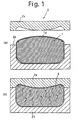
- an article 1 formed by packing a bag-shaped hollow surface material 1a having the air-permeability with the filler material mixed with a water reactive binder is positioned in a molding device 2 having a predetermined cavity comprising of an upper and a lower molds 2a, 2b and is then clamped therein.
- a molding device 2 having a predetermined cavity comprising of an upper and a lower molds 2a, 2b and is then clamped therein.
- steam is passed through the inside of the molding device 2.
- the binder reacts with the steam so that the filler material is adhered each other and is adhered with the inner surface of the surface material.
- a product 3 having a predetermined shape is molded in one with the surface material without producing wrinkle on the surface material and curving the seam line of the surface material.
- FIG. 2 An article 1 as described above is molded by use of a suction-type packing container shown in Fig.2.
- the suction-type packing container 3 is composed of a lower part 3b and an upper part 3a that can seal the inside of the suction-type packing container 3, and as shown in Fig.2, a bag-shaped hollow surface material 1a having an opening 1b is positioned inside the suction-type packing container 3.
- the lower part 3b has a suction port 4 connected to a suction pump and an entry port 5 for delivering a filler material T through this entry port 5.
- a funnel 6 is positioned such that the funnel 6 passes through the entry port 5 and comes into the inside of the surface material 1a through the opening 1b thereof.
- air inside the suction-type packing container 3 is evacuated and the inside of the suction-type packing container 3 is decompressed so that air is entered in the inside of the suction-type packing container 3 through the entry port 5 and the opening 1b via the funnel 6.
- the filler material T is delivered by the airflow to the inside of the surface material 1a, and thereby the surface material 1a is packed with the filler material T.
- granular or fragmental waste of surface material and urethane foam can be recycled to manufacture a seat and an accessory used for an automobile.
- a filler material should be stably delivered through the entry port of the suction-type packing container by use of airflow when a bag-shaped hollow surface material is packed with the filler material as described above, and in order to achieve that the filler material is stably delivered through the entry port, it is necessary that the filler material should be mixed evenly with the airflow. If the filler material is concentrated locally in the airflow or if there is a mass of the filler material in the airflow, the entry port may be blocked so that the filler material cannot be delivered through the entry port.
- the filler material may be unevenly packed in the surface material so that the filler material is not stably adhered each other and with the inner surface of the surface material even though the filler material is pre-mixed with a binder.
- an object of the present invention is to provide a filler material packing system and method capable of delivering a scattered filler material to the entry port
- Another object of the present invention is to provide such a filler material packing system and method in which the filler material is delivered in a uniform density to the inside of a bag-shaped hollow surface material.
- the other object of the present invention is to provide such a filler material packing system and method in which the filler material is stably delivered to the inside of the surface material.
- the suction-type packing container has an inner space, the surface material is positioned in the inner space.
- the suction-type packing container has a suction port connected to the suction pump, and thereby the inner space is connected to the suction pump.
- the suction-type packing container has an entry port provided in coaxial with an opening of the surface material, and the filler material is delivered in the surface material through the entry port and the opening of the surface material.
- the feeder has a lid, a sidewall and a bottom wall.
- Air vent holes and an outlet port are provided in an upper part of the feeder.
- the outlet port is connected to the entry port of the suction-type packing container through connecting means, and thereby, the air vent holes are connected to the entry port
- the bottom wall of the feeder is vertically movable. At least a part of the surface material is air-permeable.
- the suction-type packing container is composed of an upper part and a lower part and those parts are pivotally connected each other.
- a molding device is placed in the inner space of the suction-type packing container.
- the molding device has an upper mold and a lower mold, and a cavity that can position the surface material is formed by those molds. Those molds have suction holes that connect between the inside and the outside of the cavity.
- the molding device has an inlet coaxial with the entry port of the suction-type packing container.
- the upper mold of the molding device is fixed to the upper part of the suction-type packing container, and the lower mold of the molding device is fixed to the lower part of the suction-type packing container. Thereby, when the upper part of the suction-type packing container is opened with respect to its lower part, the upper mold of the molding device is simultaneously opened with respect to the lower mold of the molding device.
- the opening of the surface material is desirably connected with the entry port of the suction-type packing container using a funnel.
- the bottom wall of the feeder is desirably moved vertically using an air cylinder.
- the filler material is packed in the surface material using the filler material packing system described above.
- a necessary amount of the filler material is brought in the feeder.
- the bottom wall of the feeder is positioned so as to form a predetermined space between the lid of the feeder and an upper surface of the filler material brought therein.
- the outlet of the feeder is connected to the entry port of the suction-type packing container through the connecting means.
- the suction pump is driven, and as a result, airflow is formed through the filler material packing system.
- the airflow is formed from the air vent holes of the feeder to the outlet port of the feeder, from the outlet port to the entry port of the suction-type packing container through the connecting means and from the opening of the surface material coaxial with the entry port to the suction port of the suction-type packing container through the inside of the surface material.
- the bottom wall of the feeder is moved upward in order to necessarily mix the air and the filler material in the space between the lid of the feeder and the upper surface of the filler material brought therein.
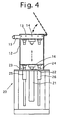
- Fig.3 shows a filler material packing system 10 according to the present invention.
- the filler material packing system 10 is composed of a feeder 11, a suction-type packing container 30, and a connector 50 for connecting between the feeder 11 and the suction-type packing container 30.
- the feeder 11 delivers a granular or fragmental filler material brought therein to the suction-type packing container 30.
- a lid 13 is provided with a hinge on a top end of a cylindrical sidewall 12, and the feeder 11 has a plurality of air vent holes 14 provided around an upper part of the sidewall 12. Those air vent holes 14 are provided for drawing air into a space formed inside the cylindrical sidewall 12, as described below. Such air vent holes may be provided not only around the cylindrical sidewall 14 but also on the lid 13.
- the feeder 11 has an outlet port 15 for delivering the filler material from the feeder to the suction-type packing container. Also, the feeder 11 has a bottom wall 16 vertically movable in the space formed inside the cylindrical sidewall 12.
- a lift 20 is provided under the cylindrical sidewall 12, and the bottom wall 16 can be moved vertically inside the cylindrical sidewall 12 by driving the lift 20.
- the lift 20 has an air cylinder 21, and a main shaft 22 of the air cylinder 21 is fixed on a back surface of the bottom wall 16.
- the lift 20 has two additional shafts 23, 24, and those shafts 23, 24 are fixed on the back surface of the bottom wall 16. Those additional shafts 23, 24 extend downward so as to pass through cylindrical supports 25, 26 fixed on the lift 20, so that a wall surface of the bottom wall 16 can be maintained in horizontal when the bottom wall 16 is moved vertically.
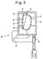
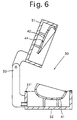
- the suction-type packing container 30 is shown in Figs. 5 and 6.
- the suction-type packing container 30 is composed of an upper part 31 and a lower part 32, and the upper part 31 is connected with the lower part 32 by use of a connector 32 so as to freely open and close those portions. When those parts are closed, a cavity is formed therein.
- a seal material 32' (Fig.6) is provided on a connection between those parts 31, 32.
- An entry port 34 for delivering a filler material to the inside thereof is also provided in a part of the connection.
- a suction port 35 is provided in the lower part 32, and its location is opposite to the entry port 34.
- the suction port 35 is connected to a suction pump.
- the connector 50 connects between the entry port 34 of the suction-type packing container 30 and the outlet port 15 of the feeder 10.
- the connector 50 has a flexible pipe 51, and an end of the flexible pipe 51 can be attached to the entry port 34 by use of a pipe-guiding device 51.
- air inside the suction-type packing container is evacuated and air inside the feeder (i.e. air presented in a space between the lid 13 and the bottom wall 16) is also evacuated through the pipe 51 connected between the entry port 34 of the suction-type packing container 30 and the outlet port 15 of the feeder 10.
- air is drawn into the feeder 11 through the air vent holes 14, so that airflow is formed by driving the suction pump from the air vent holes 14 to the suction port 35 through the inside of the feeder 11, the pipe 51 of the connector 50, the entry port 34 and the inside of the suction-type packing container 30.
- an air-permeable bag-shaped hollow surface material (shown below as an example) is positioned in the suction-type packing container 30 so as to match an opening of the surface material to the entry port 34, and a necessary filler material is brought into the feeder. Then, the suction pump is driven. The filler material is delivered to the inside of the surface material together with the airflow described above, and as a result, an article composed of the surface material and the filler material packed therein is formed. If it is necessary to mold the article, a molding device 40 is arranged inside the suction-type packing container 30.
- the molding device 40 arranged in the suction-type packing container 30 is composed of an upper mold 42 and a lower mold 41.
- An inlet port 43 coaxial with the entry port 34 is provided in a connection between those upper and lower molds 42, 41.
- Those upper and lower molds 42, 41 have a plurality of suction holes 44 connected between the inside and the outside of the molding device 40.
- the lower mold 42 is fixed to the lower part 32 of the suction-type packing container 30, and the upper mold 42 is the upper part 31 of the suction-type packing container 30.
- the upper mold 42 is moved together with the upper part 31 with respect to the lower mold 41.
- a material used as the filler material includes chips of urethane foam, fabric, soft slab urethane foam produced in manufacturing steps in a seat and a headrest of an automobile.
- a material used as the filler material includes not only the above materials but also shredder dusts of a used automobile and light-weight materials such as feather and powder difficult to handle and bring into the surface material.
- a headrest used for an automobile is considered and is manufactured using the filler material packing system 10 according to the present invention.
- Fig.7(a) is a front view of a surface material of a headrest H used for an automobile, and Fig.7(b) is its bottom view.
- the surface material 70 used is formed of a fiber material and is thus air-permeable.
- a soft slab urethane foam is laminated on its inner surface.
- a bottom of the surface material 70 has two circular small holes 72, 72 and a slit 73 connected between those holes 72, 72.
- the holes 72 are provided for inserting a stay in the inside of the surface material 70, and the slit 73 is provided as an opening of the surface material 70.
- the slit 73 is usually closed as shown in Fig.7(c).
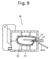
- the stay 74 is inserted in the surface material 70, and this surface material is then positioned in the molding device 40 (the upper mold 42 has been opened as shown in Fig.6).
- a funnel 75 is positioned such that the funnel 75 connects between the entry port 34 and the inlet port 43 to smoothly deliver the filler material.
- the funnel 75 is shown in detail in Fig.8.
- the funnel 75 has a plug 76 that is inserted in an end of the flexible pipe 51 and a nozzle 77 that is inserted in the surface material 70 through the entry port 34 and the slit 73 (opening) of the surface material 70.
- the nozzle 77 has an elliptical internal channel diverted from an end of the plug 76, and the diverted angle is more than 45 degrees, so that the filler material delivered via the connector 50 can be evenly packed in the surface material 70.
- the upper part 31 of the suction-type packing container 30 is closed, and simultaneously, the upper mold 42 of the molding device 40 is dosed.
- the outlet port 15 of the feeder 11 is connected with the plug 76 of the funnel 75 via the connector 50. A predetermined amount of the filler material T has been brought in the feeder 11.
- each air vent hole is ⁇ 4 and twelve holes are provided in the feeder.
- Air drawn into the feeder flows from the feeder through the outlet port 15 and then flows to the inside of the surface material 70 via the connector 50 and the funnel 75. Then, the air flown to the inside of the surface material 70 passes through the surface material and flows to the suction port 35 through the suction holes 44 of the molding device 40.
- air drawn through the air vent holes 14 makes air just above the filler material T on the bottom wall 16 turbulent such that a top portion of the filler material T is blown up by the turbulent airflow, and as a result, the filler material blown up is scattered and is mixed with the air. If the filler material is delivered to the connector 50 together with the air, a mass of the filler material is not formed and the filler material is stably supplied in the surface material.
- a condition of such a turbulent airflow mainly depends on the airflow through the air vent holes 14 and a space between the lid 13 of the feeder 11 and an upper surface of the filler material T on the bottom wall 16. If each air vent hole 14 of a feeder has a fixed size, the size of the space between the lid 13 and the upper surface of the filler material T on the bottom wall 16 can be adjusted by moving the bottom wall 16 vertically.
- the bottom wall 16 of the feeder 11 is movable vertically so that the filler can be desirably mixed with airflow through the air vent holes 14.
- a necessary amount of the filler material is brought in the feeder 11, and the bottom wall 16 is moved upward and downward so as to form a necessary space size above the filler material brought on the bottom wall 16. Then, the air cylinder 21 is driven.
- the filler material flows out together with the airflow through the outlet port 15.
- the filler material mixed with the air passes through the connector 50 and is delivered to the inside of the surface material 70 through the funnel 75 disposed through the entry port 34.
- the air passes through the surface material 70 while the filler material remains inside the surface material 70.
- the air is then introduced to the suction port 35 through the suction holes 44.
- the space above the filler material in the feeder is changed during delivering the filler material.
- the bottom wall 16 is moved upward by driving the air cylinder.
- the operation of the bottom wall 16 and the vacuum source is stopped.
- a predetermined amount of the filler material is packed in the bag-shaped hollow surface material, and thereby an article formed by packing the filler material in the surface material is produced.
- an amount of the filler material to be charged in the feeder is an amount necessary for only one surface material.
- an amount necessary for a plurality of surface materials may be charged in the feeder. If the amount necessary for a plurality of surface materials is charged therein, the operation of the vacuum source and the air cylinder is stopped when a predetermined amount of the filler material necessary for one surface material has been delivered through the outlet port to the inside of the surface material. Then, the surface material in the suction-type packing container is replaced with another surface material. Thus, an article formed by packing the filler material in the surface material can be continuously formed.
- the article 79 slightly expands more than its predetermined shape, even though the surface material is formed in a predetermined shape.
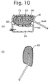
- the molding device 80 has an upper mold 81 and a lower mold 82, and a predetermined space is formed by those upper and lower molds 81, 82.
- the molding device 80 has holes 83, and steam passes through those holes 83.
- a steam chamber 84 is provided under the lower mold 82, and steam is entered into the steam chamber 84 and is then entered into the space between the upper and the lower molds 81, 82 through the holes 83 provided in the lower mold 82.
- the steam entered into the space of the molding device 80 passes through the article 79 and is then evacuated through the holes 83 of the upper mold 81.
- the article packed the filler material in the surface material is ejected from the molding device, and then, it is set in a dryer at 120 centigrade degrees for one hour to remove residual water, and thereby, a complete article 85 is produced (Fig.10(b)).
- the density of the filler material in the bag-shaped hollow surface material is even and its shape is formed in a desirable shape. If the filler material is mixed with a binder, the filler material can adhere each other and adhere to an inner surface of the surface material.
- the filler material is stably packed in the surface material, and thereby, the packing work becomes efficiency and its quality becomes even.
- waste such as chips of urethane foam and fragments of surface material is produced.
- the filler material can be packed in the bag-shaped hollow surface material.
- chips of urethane foam and fragments of surface material were wasted.
- such waste can be recycled.
Landscapes
- Engineering & Computer Science (AREA)
- Mechanical Engineering (AREA)
- Robotics (AREA)
- Processing And Handling Of Plastics And Other Materials For Molding In General (AREA)
- Basic Packing Technique (AREA)
- Casting Or Compression Moulding Of Plastics Or The Like (AREA)
Abstract
Description
Claims (9)
- A filler material packing system for packing a granular or fragmental filler material in a bag-shaped hollow surface material, including:a suction pump;a suction-type packing container having an inner space for positioning the surface material, a suction port connected between said suction pump and said inner space, and an entry port provided in coaxial with an opening of said surface material, said filler material being delivered in said surface material through said entry port and said opening; anda feeder for delivering said filler material, said feeder having a lid, a sidewall and a bottom wall, air vent holes and an outlet being provided in an upper part of said feeder, said outlet being connected to said entry port through connecting means, said bottom wall being movable vertically.
- The filler material packing system of claim 1 wherein said suction-type packing container has an upper part and a lower part, said upper and lower parts being pivotally connected each other,a molding device is provided in said suction-type packing container, said molding device having an upper mold and a lower mold, and said surface material is positioned in a cavity formed by said upper and lower molds,said upper and lower molds have suction holes that connect between the inside of said cavity and the outside of said cavity,said molding device has an inlet provided in coaxial with said entry port of said suction-type packing container, andsaid upper mold of said molding device is fixed to said upper part of said suction-type packing container, and said lower mold of said molding device is fixed to said lower part of said suction-type packing container, and thereby, when said upper part of said suction-type packing container is opened and closed with respect to said lower part thereof, said upper mold of said molding device is simultaneously opened and closed with respect to said lower mold of said molding device.
- The filler material packing system of claim 1 wherein said opening of said surface material is connected to said entry port of said suction-type packing container using a funnel.
- The filler material packing system of claim 3 wherein a sectional shape of said entry port is circle, andsaid funnel has a cylindrical plug matched to said entry port and a nozzle that has an elliptical internal channel diverted from an end of said plug in one direction and is tapered in another direction perpendicular to said one direction.
- The filler material packing system of claim 4 wherein the diverted angle of said nozzle of said funnel is at least 45 degrees.
- The filler material packing system of claim 1 wherein said feeder has an air cylinder connected to said bottom wall of said feeder to move said bottom wall vertically.
- A method for packing said filler material in said surface material using said filler material packing system of claim 1 or 2, comprising steps of:bringing a necessary amount of said filler material in said feeder;positioning said bottom wall of said feeder so as to form a predetermined space between said lid of said feeder and an upper surface of said filler material brought therein;driving said suction pump, said outlet of said feeder being connected to said entry port of said suction-type packing container through said connecting means, so that airflow is formed through said filler material packing system, said airflow being formed from said air vent holes of said feeder to said outlet port of said supply port, from said outlet port to said entry port of said suction-type packing container through said connecting means and from said opening of said surface material coaxial with said entry port to said suction port of said suction-type packing container through the inside of said surface material; andmoving said bottom wall of said feeder upward in order to necessarily mix the air and said filler material in the space between said lid of said feeder and said upper surface of said filler material brought therein, when said airflow is formed.
- The method of claim 7 wherein said filler material is selected from granules or fragments of urethane foam, fabric, plastics or a mixture thereof.
- The method of claim 8 wherein a water reactive binder is premixed with said filler material,said binder is a water reactive urethane binder,steam is passed through an article formed by packing said filler material in said surface material, and thereby said filler material is adhered each other and is adhered with an inner surface of said surface material.
Applications Claiming Priority (3)
| Application Number | Priority Date | Filing Date | Title |
|---|---|---|---|
| JP2000155907A JP3649654B2 (en) | 2000-05-26 | 2000-05-26 | Filling apparatus and method |
| JP2000155907 | 2000-05-26 | ||
| PCT/JP2000/006886 WO2001089793A1 (en) | 2000-05-26 | 2000-10-03 | Filling device and filling method |
Publications (3)
| Publication Number | Publication Date |
|---|---|
| EP1219399A1 true EP1219399A1 (en) | 2002-07-03 |
| EP1219399A4 EP1219399A4 (en) | 2003-03-26 |
| EP1219399B1 EP1219399B1 (en) | 2004-06-16 |
Family
ID=18660772
Family Applications (1)
| Application Number | Title | Priority Date | Filing Date |
|---|---|---|---|
| EP00963082A Expired - Lifetime EP1219399B1 (en) | 2000-05-26 | 2000-10-03 | Filling device and filling method |
Country Status (7)
| Country | Link |
|---|---|
| US (1) | US6588462B1 (en) |
| EP (1) | EP1219399B1 (en) |
| JP (1) | JP3649654B2 (en) |
| KR (1) | KR100763455B1 (en) |
| CA (1) | CA2379979A1 (en) |
| DE (1) | DE60011647T2 (en) |
| WO (1) | WO2001089793A1 (en) |
Cited By (2)
| Publication number | Priority date | Publication date | Assignee | Title |
|---|---|---|---|---|
| EP1354684A1 (en) * | 2002-04-30 | 2003-10-22 | Recticel | Method and installation for producing a moulded bonded foam article |
| ITRE20090025A1 (en) * | 2009-03-19 | 2010-09-20 | Cgm Spa | METHOD FOR REALIZING PLASTIC PRODUCTS |
Families Citing this family (9)
| Publication number | Priority date | Publication date | Assignee | Title |
|---|---|---|---|---|
| US7540307B1 (en) * | 2004-10-06 | 2009-06-02 | Indratech Llc | Machine having variable fiber filling system for forming fiber parts |
| US20070005375A1 (en) * | 2005-06-08 | 2007-01-04 | Lauer Toys Incorporated | Method of retailing and associated interactive retail store environment |
| KR101417653B1 (en) | 2013-06-25 | 2014-07-09 | 문중민 | A filling apparatus for plume |
| USD753731S1 (en) * | 2014-07-18 | 2016-04-12 | Fill Station Group, LLC | Pillow creation kiosk |
| US11324337B2 (en) * | 2016-08-17 | 2022-05-10 | Worldwise, Inc. | Bed filling system |
| US11351702B1 (en) | 2016-10-05 | 2022-06-07 | Auria Solutions Uk I Ltd. | Three dimensional fiber deposited multi-layered/multi-blend molded fiber parts |
| US12252051B2 (en) | 2020-07-08 | 2025-03-18 | Auria Solutions UK I, Ltd. | Fiber based compositions for noise abatement and compression resistance |
| CN112520681A (en) * | 2020-11-11 | 2021-03-19 | 安徽西格玛服饰有限公司 | Down filling mechanism for down filling machine |
| CN116570086B (en) * | 2023-05-19 | 2025-08-05 | 高梵(浙江)信息技术有限公司 | A kind of production equipment for leak-proof and breathable goose down fabric |
Family Cites Families (19)
| Publication number | Priority date | Publication date | Assignee | Title |
|---|---|---|---|---|
| US2753220A (en) * | 1953-03-27 | 1956-07-03 | Maxwell F Kemper | Apparatus for controlling the application of concrete in the lining of tunnels |
| FR1542605A (en) * | 1966-07-29 | Werz Furnier Sperrholz | Method for filling molds in press molding and device for carrying out this method | |
| US3693836A (en) * | 1970-11-10 | 1972-09-26 | York Feather & Down Corp | Filling machine |
| JPS5850579B2 (en) | 1978-03-28 | 1983-11-11 | 積水化成品工業株式会社 | Foam molding method |
| DE2814140A1 (en) * | 1978-04-01 | 1979-10-11 | Stotz Ag A | FOUNDRY FORMING MACHINE |
| US4473526A (en) * | 1980-01-23 | 1984-09-25 | Eugen Buhler | Method of manufacturing dry-pressed molded articles |
| US4664160A (en) | 1984-11-19 | 1987-05-12 | Ormont Corporation | Fiber filling system |
| US4900200A (en) * | 1988-06-22 | 1990-02-13 | Matsui Manufacturing Co., Ltd. | Method for transporting powdered or granular materials by pneumatic force with a transport pipe of smaller diameter relative to particale size |
| US5034167A (en) * | 1990-09-17 | 1991-07-23 | General Motors Corporation | Apparatus and method for eliminating static charge from polystyrene beads for pattern molding |
| US5340241A (en) * | 1992-02-04 | 1994-08-23 | Motan, Inc. | Device for metering and entraining a product into a gas stream |
| JP2932454B2 (en) * | 1993-05-20 | 1999-08-09 | 三菱化学ビーエーエスエフ株式会社 | Composite molded article and method for producing the same |
| US5503198A (en) * | 1994-10-14 | 1996-04-02 | Becker; James R. | Method and apparatus for filling containers with dry ice pellets |
| JPH08258059A (en) | 1995-03-24 | 1996-10-08 | Achilles Corp | Production of skin material integrally molded seat member |
| JPH0984972A (en) | 1995-09-22 | 1997-03-31 | Teijin Ltd | Molding method for fiber assembly and apparatus therefor |
| US5967704A (en) * | 1995-09-22 | 1999-10-19 | Cipriani; Gary | Pneumatic apparatus for conveying a dry granular material |
| US5571465A (en) * | 1995-12-18 | 1996-11-05 | General Motors Corporation | Method for making fiber-filled bolstered cushion |
| WO1998024958A1 (en) * | 1996-12-05 | 1998-06-11 | Teijin Limited | Fiber aggregate molding method |
| US5931610A (en) * | 1997-05-19 | 1999-08-03 | Arr-Maz Products, L.P. | Fiber dispensing system |
| JP3697474B2 (en) | 1997-07-30 | 2005-09-21 | 帝人ファイバー株式会社 | Molding method for fiber assembly |
-
2000
- 2000-03-10 US US10/018,635 patent/US6588462B1/en not_active Expired - Fee Related
- 2000-05-26 JP JP2000155907A patent/JP3649654B2/en not_active Expired - Fee Related
- 2000-10-03 EP EP00963082A patent/EP1219399B1/en not_active Expired - Lifetime
- 2000-10-03 CA CA002379979A patent/CA2379979A1/en not_active Abandoned
- 2000-10-03 DE DE60011647T patent/DE60011647T2/en not_active Expired - Lifetime
- 2000-10-03 WO PCT/JP2000/006886 patent/WO2001089793A1/en not_active Ceased
- 2000-10-03 KR KR1020017015881A patent/KR100763455B1/en not_active Expired - Fee Related
Cited By (5)
| Publication number | Priority date | Publication date | Assignee | Title |
|---|---|---|---|---|
| EP1354684A1 (en) * | 2002-04-30 | 2003-10-22 | Recticel | Method and installation for producing a moulded bonded foam article |
| WO2003092983A1 (en) * | 2002-04-30 | 2003-11-13 | Recticel | Method and installation for producing a moulded bonded foam article |
| ITRE20090025A1 (en) * | 2009-03-19 | 2010-09-20 | Cgm Spa | METHOD FOR REALIZING PLASTIC PRODUCTS |
| EP2230060A1 (en) * | 2009-03-19 | 2010-09-22 | C.G.M. S.P.A. | A compression moulding method for realising thermoplastic products |
| US8652389B2 (en) | 2009-03-19 | 2014-02-18 | C.G.M. S.P.A. | Compression moulding method for realising thermoplastic products |
Also Published As
| Publication number | Publication date |
|---|---|
| CA2379979A1 (en) | 2001-11-29 |
| KR20020028895A (en) | 2002-04-17 |
| DE60011647T2 (en) | 2004-11-11 |
| EP1219399A4 (en) | 2003-03-26 |
| US6588462B1 (en) | 2003-07-08 |
| KR100763455B1 (en) | 2007-10-05 |
| DE60011647D1 (en) | 2004-07-22 |
| WO2001089793A1 (en) | 2001-11-29 |
| EP1219399B1 (en) | 2004-06-16 |
| JP3649654B2 (en) | 2005-05-18 |
| JP2001335001A (en) | 2001-12-04 |
Similar Documents
| Publication | Publication Date | Title |
|---|---|---|
| US6588462B1 (en) | Filling device and filling method | |
| US4685872A (en) | Machine for the production of molded parts from foamed plastic | |
| US6899147B2 (en) | Filling device and method | |
| KR20110133578A (en) | Milk foam making equipment | |
| EP1284848B1 (en) | Method and apparatus for making expanded plastics containers | |
| AU603458B2 (en) | Process and vacuum mold for the manufacture of a textile covered cushion | |
| CN215473299U (en) | Cold isostatic pressing device | |
| US6946043B1 (en) | Filled article | |
| CN211640762U (en) | Material storage and conveying system of injection molding machine | |
| ES2208629T3 (en) | METHOD AND INSTALLATION FOR THE MANUFACTURE OF AN ARTICLE OF BINDING MATERIAL, SPONGE, BY MOLDING. | |
| JP2006014808A (en) | Wadding injector | |
| JPS61254306A (en) | Supplying of expandable grains and device thereof | |
| JPH0957143A (en) | Method and apparatus for producing frp powder | |
| KR20180074932A (en) | Cover unwrinkling type mold and molding method using the same | |
| JPS58163630A (en) | Method and apparatus for formed molding | |
| JPH05162214A (en) | Molding method and molding apparatus for foam molded article | |
| JPH0479831B2 (en) | ||
| JPH1148347A (en) | Method and apparatus for feeding foamed beads |
Legal Events
| Date | Code | Title | Description |
|---|---|---|---|
| PUAI | Public reference made under article 153(3) epc to a published international application that has entered the european phase |
Free format text: ORIGINAL CODE: 0009012 |
|
| 17P | Request for examination filed |
Effective date: 20020201 |
|
| AK | Designated contracting states |
Kind code of ref document: A1 Designated state(s): AT BE CH CY DE DK ES FI FR GB GR IE IT LI LU MC NL PT SE |
|
| AX | Request for extension of the european patent |
Free format text: AL;LT;LV;MK;RO;SI |
|
| A4 | Supplementary search report drawn up and despatched |
Effective date: 20030212 |
|
| 17Q | First examination report despatched |
Effective date: 20030410 |
|
| GRAP | Despatch of communication of intention to grant a patent |
Free format text: ORIGINAL CODE: EPIDOSNIGR1 |
|
| GRAS | Grant fee paid |
Free format text: ORIGINAL CODE: EPIDOSNIGR3 |
|
| GRAA | (expected) grant |
Free format text: ORIGINAL CODE: 0009210 |
|
| AK | Designated contracting states |
Kind code of ref document: B1 Designated state(s): DE FR GB IT SE |
|
| PG25 | Lapsed in a contracting state [announced via postgrant information from national office to epo] |
Ref country code: IT Free format text: LAPSE BECAUSE OF FAILURE TO SUBMIT A TRANSLATION OF THE DESCRIPTION OR TO PAY THE FEE WITHIN THE PRESCRIBED TIME-LIMIT;WARNING: LAPSES OF ITALIAN PATENTS WITH EFFECTIVE DATE BEFORE 2007 MAY HAVE OCCURRED AT ANY TIME BEFORE 2007. THE CORRECT EFFECTIVE DATE MAY BE DIFFERENT FROM THE ONE RECORDED. Effective date: 20040616 |
|
| REG | Reference to a national code |
Ref country code: GB Ref legal event code: FG4D |
|
| REF | Corresponds to: |
Ref document number: 60011647 Country of ref document: DE Date of ref document: 20040722 Kind code of ref document: P |
|
| REG | Reference to a national code |
Ref country code: IE Ref legal event code: FG4D |
|
| PG25 | Lapsed in a contracting state [announced via postgrant information from national office to epo] |
Ref country code: SE Free format text: LAPSE BECAUSE OF FAILURE TO SUBMIT A TRANSLATION OF THE DESCRIPTION OR TO PAY THE FEE WITHIN THE PRESCRIBED TIME-LIMIT Effective date: 20040916 |
|
| LTIE | Lt: invalidation of european patent or patent extension |
Effective date: 20040616 |
|
| ET | Fr: translation filed | ||
| PLBE | No opposition filed within time limit |
Free format text: ORIGINAL CODE: 0009261 |
|
| STAA | Information on the status of an ep patent application or granted ep patent |
Free format text: STATUS: NO OPPOSITION FILED WITHIN TIME LIMIT |
|
| 26N | No opposition filed |
Effective date: 20050317 |
|
| REG | Reference to a national code |
Ref country code: IE Ref legal event code: MM4A |
|
| PGFP | Annual fee paid to national office [announced via postgrant information from national office to epo] |
Ref country code: GB Payment date: 20081001 Year of fee payment: 9 |
|
| PG25 | Lapsed in a contracting state [announced via postgrant information from national office to epo] |
Ref country code: GB Free format text: LAPSE BECAUSE OF NON-PAYMENT OF DUE FEES Effective date: 20091003 |
|
| PGFP | Annual fee paid to national office [announced via postgrant information from national office to epo] |
Ref country code: FR Payment date: 20141008 Year of fee payment: 15 Ref country code: DE Payment date: 20140930 Year of fee payment: 15 |
|
| REG | Reference to a national code |
Ref country code: DE Ref legal event code: R119 Ref document number: 60011647 Country of ref document: DE |
|
| PG25 | Lapsed in a contracting state [announced via postgrant information from national office to epo] |
Ref country code: DE Free format text: LAPSE BECAUSE OF NON-PAYMENT OF DUE FEES Effective date: 20160503 |
|
| REG | Reference to a national code |
Ref country code: FR Ref legal event code: ST Effective date: 20160630 |
|
| PG25 | Lapsed in a contracting state [announced via postgrant information from national office to epo] |
Ref country code: FR Free format text: LAPSE BECAUSE OF NON-PAYMENT OF DUE FEES Effective date: 20151102 |