EP1219382A2 - Laser beam projector - Google Patents
Laser beam projector Download PDFInfo
- Publication number
- EP1219382A2 EP1219382A2 EP01130660A EP01130660A EP1219382A2 EP 1219382 A2 EP1219382 A2 EP 1219382A2 EP 01130660 A EP01130660 A EP 01130660A EP 01130660 A EP01130660 A EP 01130660A EP 1219382 A2 EP1219382 A2 EP 1219382A2
- Authority
- EP
- European Patent Office
- Prior art keywords
- turning
- optical head
- laser beam
- holding
- beam projector
- Prior art date
- Legal status (The legal status is an assumption and is not a legal conclusion. Google has not performed a legal analysis and makes no representation as to the accuracy of the status listed.)
- Granted
Links
Images


Classifications
-
- B—PERFORMING OPERATIONS; TRANSPORTING
- B23—MACHINE TOOLS; METAL-WORKING NOT OTHERWISE PROVIDED FOR
- B23K—SOLDERING OR UNSOLDERING; WELDING; CLADDING OR PLATING BY SOLDERING OR WELDING; CUTTING BY APPLYING HEAT LOCALLY, e.g. FLAME CUTTING; WORKING BY LASER BEAM
- B23K26/00—Working by laser beam, e.g. welding, cutting or boring
- B23K26/02—Positioning or observing the workpiece, e.g. with respect to the point of impact; Aligning, aiming or focusing the laser beam
- B23K26/06—Shaping the laser beam, e.g. by masks or multi-focusing
- B23K26/064—Shaping the laser beam, e.g. by masks or multi-focusing by means of optical elements, e.g. lenses, mirrors or prisms
-
- B—PERFORMING OPERATIONS; TRANSPORTING
- B23—MACHINE TOOLS; METAL-WORKING NOT OTHERWISE PROVIDED FOR
- B23K—SOLDERING OR UNSOLDERING; WELDING; CLADDING OR PLATING BY SOLDERING OR WELDING; CUTTING BY APPLYING HEAT LOCALLY, e.g. FLAME CUTTING; WORKING BY LASER BEAM
- B23K26/00—Working by laser beam, e.g. welding, cutting or boring
- B23K26/08—Devices involving relative movement between laser beam and workpiece
- B23K26/0869—Devices involving movement of the laser head in at least one axial direction
- B23K26/0876—Devices involving movement of the laser head in at least one axial direction in at least two axial directions
- B23K26/0884—Devices involving movement of the laser head in at least one axial direction in at least two axial directions in at least three axial directions, e.g. manipulators, robots
Definitions
- the present invention relates to a laser beam projector. More specifically, the present invention relates to a laser beam projector capable of being incorporated into an automatic welding head held on the free end of a robot arm or the like and of projecting a laser beam accurately on a portion to be welded.
- Butt welding using a laser beam is used prevalently for welding members in order to manufacture automobiles, etc.
- CO 2 lasers have been replaced by YAG lasers capable of focusing a laser beam in a spot smaller than that which is formable by CO 2 lasers.
- a welding process using a YAG laser capable of focusing a laser beam in a small spot is able to achieve fine welding using a small laser-beam spot.
- fine welding requires forming the laser-beam spot at a groove in a positional accuracy on the order of 0.05 mm.
- a laser beam machine described in JP-A 328867/1998 comprises a work table for holding a tensioned plate-shaped workpiece and axially moving the workpiece, a laser beam machining head including an optical focusing system for focusing a laser beam and capable of axial movement for focusing a laser beam on the workpiece, an upper workpiece holding member integrally provided with a laser beam projecting nozzle, a hollow, expansion connecting member interconnecting the laser beam machining head and the upper workpiece holding member such that the laser beam machining head and the upper workpiece holding member can be moved relative to each other for focusing the laser beam, and a lower stationary surface plate.
- the workpiece is held between the upper workpiece holding member and the lower stationary surface plate at a position near a laser beam machining position.
- This known laser beam machine moves the work table supporting the workpiece thereon to make the laser beam trace a desired path. Therefore, the laser beam machine is inevitably large and is subject to restrictions on the shape of the workpiece.
- the present invention has been made in view of the foregoing problem and it is therefore an object of the present invention to provide a laser beam projector capable of being mounted on an automatic welding machine, such as a welding robot, of assisting the operation of the automatic welding machine and of projecting a laser beam on a portion to be welded in a high accuracy.
- a laser beam projector comprising: an optical head of projecting a laser beam; and a holding-turning mechanism of holding and turning the optical head.
- holding-turning mechanism holds the optical head so that the optical head is able to turn about an axis passing a center of gravity of the optical head.
- the holding-turning mechanism includes a first holding-turning unit of turning the optical head in a direction perpendicular to a weld line and a second holding-turning unit of turning the optical head in a direction of the weld line.
- the holding-turning mechanism includes a turning link mechanism of transmitting a driving force to the optical head in order to turn the optical head.
- the optical head may be a head which emits a YAG laser beam.
- the optical head may be mounted on a robot arm, and so on.
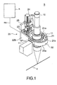
- the laser beam projector S is attached to the extremity of a robot arm RA of a robot R to irradiate a weld zone accurately with a laser beam in cooperation with the motion of the robot arm.
- the laser beam projector S includes, as essential components, an optical head 10 provided with a YAG laser that emits a laser beam, and a holding-turning mechanism 20 capable of holding and turning the optical head 10 thereon.
- the optical head 10 has a shape substantially resembling a stepped cylinder. A laser beam emitted by the YAG laser is projected through a laser beam projecting end of the optical head 10 on a workpiece.
- the optical head 10 is the same in configuration as an optical head included in a known YAG laser beam projector and hence the detailed description thereof will be omitted.
- a pair of shafts 11 are attached to parts of the cylindrical optical head 10 so as to extend in opposite directions, respectively, with their common axis passing the center of gravity of the optical head 10.
- the holding-turning mechanism 20 turns the optical head 10 on the shafts 11.
- the optical head 10 is held by the holding-turning mechanism 20 with its laser beam projecting end facing down.
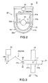
- the holding-turning mechanism 20 includes a turning frame 21 supporting the optical head 10, a holding frame 22 pivotally supporting the turning frame 21, a turning mechanism 23 including a motor 24 and a turning link mechanism 23A, and a joining member 25 joined to the holding frame 22.
- a flange, not shown, formed integrally with the joining member 25 is fastened to a flange, not shown, attached to the extremity of the robot arm with bolts and nuts.
- the turning frame 21 is formed by joining the free ends of opposite side parts of a U-shaped member 21a to the opposite ends of a semicircular member 21b.
- the optical head 10 is supported on the turning frame 21 with the shafts 11 fixedly extended through the opposite side parts of the U-shaped member 21a.
- the holding frame 22 is a U-shaped frame formed by joining plate-shaped side members 22b to the opposite ends of a semicircular member 22a.
- the radius of curvature of the semicircular member 22a is greater than that of the semicircular member 21b.
- the turning frame 21 is surrounded by the holding frame 22.
- the respective semicircular members 21b of the turning frame 21 and 22a of the holding frame 22 are on the same side with respect to the optical head 10.
- the shafts 11 are supported for turning in bearings held on the plate-shaped members 22b of the holding frame 22.
- the joining member 25 is, for example, a rectangular plate.
- the opposite ends of the U-shaped holding frame 22 are joined to the opposite sides of a lower part of a surface of the joining member 25.
- the motor 24 is fastened to an upper middle part of the front surface of the joining member 25.
- the flange to be joined to the flange attached to the extremity of the robot arm is formed on the back surface of the joining member 25.
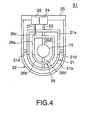
- the turning link mechanism 23A of the turning mechanism 23 has one end pivotally joined to an axially movable drive shaft 24a included in the motor 24, and the other end pivotally joined to a joint 21c attached to the outer surface of a cross part extending between the opposite side parts of the U-shaped member 21a.
- the motor 24 is driven to project the drive shaft 24a in the direction of the arrow A1 shown in Fig. 3
- the turning link mechanism 23A is turned counterclockwise as viewed in Fig. 3. Consequently, the cross part of the U-shaped member 21a is pulled up in the direction of the arrow A2 and the optical head 10 is turned clockwise as viewed in Fig. 3, so that the laser beam projecting end of the optical head 10 is moved inward, i.e., toward the robot arm, as indicated by the arrow A3.
- the optical head 10 Since the shafts 11 of the optical head 10 are supported in the bearings on the holding frame 22 as explained above, the optical head 10 is thus turned on the shafts 11 in a direction perpendicular to a weld line (groove) K shown in Fig. 1.
- the reaction force that acts on the holding-turning mechanism 20, when the optical head 10 is turned is lower than the reaction force which will acts on a holding mechanism when an optical head is translated. Since the optical head 10 is supported by the shafts 11 having the common axis passing the center of gravity of the optical head 10 and the optical head 10 is turned about the common axis of the shafts 11, the moment of inertia of the optical head 10 is small and hence the reaction force that acts on the holding-turning mechanism 20 is lower.
- the holding-turning mechanism 20 can be formed in a very small structure and easily attached to the robot arm.
- a linear motion of the drive shaft 24a of the motor 24 is converted into a turning motion of the turning frame 21 by the turning link mechanism 23A without using any reduction gear. Therefore, the turning frame 21 can be turned without any lost motion, which may be caused by backlashes in a reduction gear, and, consequently, the accuracy of laser beam projection can be improved. Moreover, weaving laser beam welding can be achieved by periodically turning the optical head 10 alternately in opposite directions.
- the laser beam projector has an optical head supported for turning about two axes perpendicular to each other.
- a first turning frame 21 is supported by shafts 21d fixed thereto on a holding frame 22 such that the first turning frame 21 is able to turn about the common axis of the shafts 21d relative to the holding frame 22.
- a second turning frame 26 is supported by shafts 26d fixed thereto on the first turning frame 21 such that the second turning frame 26 is able to turn about the common axis of the shafts 26d relative to the first turning frame 21.
- the first turning frame 21 can be turned about the common axis of the shafts 21d by a first turning mechanism 23 including a first motor 24.
- the second turning frame 26 can be turned about the common axis of the shafts 26d by a second turning mechanism 27 including a second motor 28.
- the first turning frame 21, the holding frame 22 and the first turning mechanism 23 are similar to those of the laser beam projector S in the previous embodiment, respectively.
- the second turning frame 26 is formed by joining the free ends of opposite side parts of a U-shaped member 26a to the opposite ends of a semicircular member 26b.
- the second turning frame 26 is surrounded by the first turning frame 21.
- the respective semicircular members 21b of the first turning frame 21 and 26b of the second turning frame 26 are on the same side with respect to the optical head 10.
- the optical head 10 is supported on the second turning frame 26 with the shafts 26d fixedly extended through a middle part of the U-shaped member 26a and a middle part of the semicircular member 26b.
- the shafts 26d are supported for turning in bearings held on the first turning frame 21.
- the holding frame 22 is the same in construction as that included in the laser beam projector S in the previous embodiment.
- the shafts 21d fixed to the side parts of the U-shaped member 21a of the first turning frame 21 are supported
- the turning link mechanism 27A of the second turning mechanism 27 has one end joined to an axially movable drive shaft 28a included in the motor 28 by a ball joint, and the other end joined by a ball joint to a joint 26c attached to the outer surface of a cross part extending between the opposite side parts of the U-shaped member 26a.
- the motor 28 is driven to project the drive shaft 28a in the direction of the arrow A1 shown in Figs. 5A and 5B
- the turning link mechanism 27A pulls up the joint 26c attached to the cross part of the U-shaped member 26a in the direction of the arrow A2 shown in Figs. 5A and 5B, so that the optical head 10 is turned clockwise as viewed in Fig. 5B, so that the laser beam projecting end of the optical head 10 is moved in the direction of the arrow A3 shown in Fig. 5B.
- the first turning mechanism 23 turns the optical head 10 in a direction perpendicular to a weld line (groove) K
- the second turning mechanism 27 turns the optical head 10 in a direction of the weld line K.
- the optical head 10 can be turned about two axes perpendicular to each other. Accordingly, the laser beam can be accurately projected on the groove even if the groove is curved in a complicated shape. Since the optical head 10 can be turned to make the laser beam projecting end of the optical head 10 perform a circular motion, complicated weaving operation is possible.
- the first turning mechanism 23 of the previous embodiments may be provided, instead of the turning link mechanism 23A, with a turning link mechanism 23B formed by pivotally joining two links by a joint, and having one end fixed to the drive shaft 24a of the motor 24 and the other end pivotally joined to the joint 21c of the turning frame 21.
- the second turning mechanism 27 of the previous embodiment may be provided, instead of the turning link mechanism 27A, with a turning link mechanism 27B formed by pivotally joining two links by a ball joint, and having one end fixed to the drive shaft 28a of the motor 28 and the other end pivotally joined by a ball joint to the joint 26c of the turning frame 26.
- the turning direction of the optical head 10 when the drive shaft 24a (28a) is projected or retracted is opposite to the turning direction of the optical head 10 when using the turning link mechanism 23A (27B).
- the spot of the laser beam can be accurately located on the portion to be welded by turning the optical head, and the reaction force that acts on the holding-turning mechanism when the optical head is thus turned to adjust the position of the laser beam on the workpiece is lower than the reaction force which will act on a holding mechanism when the optical head is translated for the same purpose.
- weaving laser beam welding can be achieved by periodically turning the optical head alternately in opposite directions.
- the optical head is rotatably supported at the position corresponding to the axis passing the center of gravity thereof, the moment of inertia is small and hence the reaction force that acts on the holding mechanism is further low.
- the optical head of the laser beam projector in the preferred embodiment can be turned about the two axes perpendicular to each other in a direction perpendicular to the weld line and in a direction of the weld line, the spot of the laser beam can be further accurately located on the portion to be welded and complicated weaving operations can be achieved.
- the turning frame can be turned without any lost motion which may be caused by backlashes in a reduction gear, and, consequently, the spot of the laser beam can be further accurately located on the portion to be welded.
- the optical head in the preferred embodiment can be turned about two axes perpendicular to each other, the laser beam can be accurately projected on the groove even if the groove is curved in a complicated shape.
Landscapes
- Physics & Mathematics (AREA)
- Optics & Photonics (AREA)
- Engineering & Computer Science (AREA)
- Plasma & Fusion (AREA)
- Mechanical Engineering (AREA)
- Robotics (AREA)
- Laser Beam Processing (AREA)
- Laser Surgery Devices (AREA)
Abstract
Description
Claims (10)
- A laser beam projector comprising:an optical head of projecting a laser beam; anda holding-turning mechanism of holding and turning the optical head.
- The laser beam projector according to claim 1, wherein the holding-turning mechanism holds the optical head so that the optical head is able to turn about an axis passing a center of gravity of the optical head.
- The laser beam projector according to claim 1 or 2, wherein the holding-turning mechanism includes a first holding-turning unit of turning the optical head in a direction perpendicular to a weld line and a second holding-turning unit of turning the optical head in a direction of the weld line.
- The laser beam projector according to any one of claims 1 to 3, wherein the holding-turning mechanism includes a turning link mechanism of transmitting a driving force to the optical head in order to turn the optical head.
- The laser beam projector according to any one of claims 1 to 4, wherein the optical head emits a YAG laser beam.
- A robot comprising:a robot arm; anda laser beam projector attached to the robot arm, the laser beam projector including an optical head of projecting a laser beam and a holding-turning mechanism of holding and turning the optical head.
- The robot according to claim 6, wherein the holding-turning mechanism holds the optical head so that the optical head is able to turn about an axis passing a center of gravity of the optical head.
- The robot according to claim 6 or 7, wherein the holding-turning mechanism includes a first holding-turning unit of turning the optical head in a direction perpendicular to a weld line and a second holding-turning unit of turning the optical head in a direction of the weld line.
- The robot according to any one of claims 6 to 8, wherein the holding-turning mechanism includes a turning link mechanism of transmitting a driving force to the optical head in order to turn the optical head.
- The robot according to any one of claims 6 to 9, wherein the optical head emits a YAG laser beam.
Applications Claiming Priority (2)
| Application Number | Priority Date | Filing Date | Title |
|---|---|---|---|
| JP2000392079A JP3383832B2 (en) | 2000-12-25 | 2000-12-25 | Laser irradiation device |
| JP2000392079 | 2000-12-25 |
Publications (3)
| Publication Number | Publication Date |
|---|---|
| EP1219382A2 true EP1219382A2 (en) | 2002-07-03 |
| EP1219382A3 EP1219382A3 (en) | 2003-11-05 |
| EP1219382B1 EP1219382B1 (en) | 2008-09-17 |
Family
ID=18858125
Family Applications (1)
| Application Number | Title | Priority Date | Filing Date |
|---|---|---|---|
| EP01130660A Expired - Lifetime EP1219382B1 (en) | 2000-12-25 | 2001-12-21 | Laser beam projector |
Country Status (6)
| Country | Link |
|---|---|
| US (1) | US6747241B2 (en) |
| EP (1) | EP1219382B1 (en) |
| JP (1) | JP3383832B2 (en) |
| KR (1) | KR100505817B1 (en) |
| AT (1) | ATE408473T1 (en) |
| DE (1) | DE60135820D1 (en) |
Cited By (2)
| Publication number | Priority date | Publication date | Assignee | Title |
|---|---|---|---|---|
| EP2165795A4 (en) * | 2007-06-06 | 2014-01-22 | Nitto Denko Corp | Laser processing method and laser processed article |
| CN110340523A (en) * | 2019-07-26 | 2019-10-18 | 深圳市海镭激光科技有限公司 | A kind of intelligence jointed fiber bonding machine |
Families Citing this family (19)
| Publication number | Priority date | Publication date | Assignee | Title |
|---|---|---|---|---|
| US7180918B2 (en) * | 2003-05-16 | 2007-02-20 | Metal Improvement Company, Llc | Self-seeded single-frequency solid-state ring laser and system using same |
| ATE498928T1 (en) * | 2003-10-30 | 2011-03-15 | Metal Improvement Company Llc | RELAY TELESCOPE, LASER AMPLIFIER, AND LASER SHOCK RADIATION METHOD AND APPARATUS THEREOF |
| US7110171B2 (en) * | 2003-10-30 | 2006-09-19 | Metal Improvement Company, Llc | Relay telescope including baffle, and high power laser amplifier utilizing the same |
| US7209500B2 (en) * | 2003-10-30 | 2007-04-24 | Metal Improvement Company, Llc | Stimulated Brillouin scattering mirror system, high power laser and laser peening method and system using same |
| US7291805B2 (en) * | 2003-10-30 | 2007-11-06 | The Regents Of The University Of California | Target isolation system, high power laser and laser peening method and system using same |
| US7718921B2 (en) * | 2004-11-17 | 2010-05-18 | Metal Improvement Company Llc | Active beam delivery system with variable optical path segment through air |
| US7750266B2 (en) * | 2004-11-17 | 2010-07-06 | Metal Improvement Company Llc | Active beam delivery system for laser peening and laser peening method |
| US7851725B2 (en) | 2004-11-17 | 2010-12-14 | Metal Improvement Company Llc | Active beam delivery system with image relay |
| US20070210046A1 (en) * | 2006-03-07 | 2007-09-13 | Jin-Sheng Lai | Roller adjusting device of optical laser-lens seat |
| KR100835614B1 (en) | 2007-02-05 | 2008-06-05 | 아메코 주식회사 | Compound Processing Machine |
| DE102008058644A1 (en) * | 2008-10-10 | 2010-04-15 | Num Industry Alliance Ag | cutter |
| DE102009029193A1 (en) * | 2009-09-04 | 2011-03-17 | Trumpf Werkzeugmaschinen Gmbh + Co. Kg | Laser processing machine with redundant axes |
| US10072971B2 (en) | 2010-04-16 | 2018-09-11 | Metal Improvement Company, Llc | Flexible beam delivery system for high power laser systems |
| USD621864S1 (en) * | 2010-05-20 | 2010-08-17 | Emcore Corporation | Laser assembly |
| USD637637S1 (en) * | 2010-06-11 | 2011-05-10 | Emcore Corporation | Tunable Laser Assembly |
| JP5459256B2 (en) | 2011-04-08 | 2014-04-02 | 株式会社安川電機 | Robot system |
| CN102303186B (en) * | 2011-08-16 | 2013-09-04 | 江苏扬力数控机床有限公司 | Imperfect degree-of-freedom parallel connection five-axis computerized numerical control laser cutting machine |
| USD745208S1 (en) | 2013-02-12 | 2015-12-08 | Neophotonics Corporation | Support for a beam splitter |
| CN103386553B (en) * | 2013-08-14 | 2016-03-23 | 常州市璟胜自动化科技有限公司 | Laser cutting device |
Family Cites Families (11)
| Publication number | Priority date | Publication date | Assignee | Title |
|---|---|---|---|---|
| US4698479A (en) | 1984-02-06 | 1987-10-06 | Spectra-Physics, Inc. | Beam delivery system for a CO2 laser |
| US4578554A (en) | 1984-04-30 | 1986-03-25 | Teledyne, Inc. | Laser welding apparatus |
| JPS62134192A (en) | 1985-12-04 | 1987-06-17 | Toshiba Corp | Laser beam machining robot |
| EP0262198B1 (en) * | 1986-03-25 | 1992-03-25 | Laser Lab Limited | Work head device |
| JPH0323093A (en) | 1989-06-21 | 1991-01-31 | Toshiba Corp | Head of laser beam machine |
| IT1239891B (en) | 1990-02-09 | 1993-11-15 | Comau Spa | SUPPORT AND ADJUSTMENT OF A MIRROR IN A ROBOT-LASER SYSTEM, AND ROBOT-LASER SYSTEM USING SUCH DEVICE. |
| JPH03281083A (en) | 1990-03-29 | 1991-12-11 | Fanuc Ltd | Attitude control system for cnc laser beam machine |
| FR2678193B1 (en) * | 1991-06-27 | 1993-09-24 | Peugeot | LASER BEAM WELDING ROBOT. |
| JPH10328867A (en) | 1997-06-05 | 1998-12-15 | Mitsubishi Electric Corp | Laser beam processing apparatus, focus positioning jig for laser beam processing apparatus, and laser beam focusing diameter measuring jig |
| IT1297360B1 (en) * | 1997-12-31 | 1999-09-01 | Prima Ind Spa | OPERATING HEAD FOR A LASER MACHINE |
| JP2000042854A (en) | 1998-07-27 | 2000-02-15 | Babcock Hitachi Kk | Automatic tool drive |
-
2000
- 2000-12-25 JP JP2000392079A patent/JP3383832B2/en not_active Expired - Fee Related
-
2001
- 2001-12-18 US US10/020,190 patent/US6747241B2/en not_active Expired - Lifetime
- 2001-12-19 KR KR10-2001-0081332A patent/KR100505817B1/en not_active Expired - Fee Related
- 2001-12-21 DE DE60135820T patent/DE60135820D1/en not_active Expired - Lifetime
- 2001-12-21 EP EP01130660A patent/EP1219382B1/en not_active Expired - Lifetime
- 2001-12-21 AT AT01130660T patent/ATE408473T1/en not_active IP Right Cessation
Cited By (3)
| Publication number | Priority date | Publication date | Assignee | Title |
|---|---|---|---|---|
| EP2165795A4 (en) * | 2007-06-06 | 2014-01-22 | Nitto Denko Corp | Laser processing method and laser processed article |
| US9566663B2 (en) | 2007-06-06 | 2017-02-14 | Nitto Denko Corporation | Laser processing method and land laser processed product |
| CN110340523A (en) * | 2019-07-26 | 2019-10-18 | 深圳市海镭激光科技有限公司 | A kind of intelligence jointed fiber bonding machine |
Also Published As
| Publication number | Publication date |
|---|---|
| JP2002192378A (en) | 2002-07-10 |
| ATE408473T1 (en) | 2008-10-15 |
| EP1219382A3 (en) | 2003-11-05 |
| KR100505817B1 (en) | 2005-08-03 |
| US20020079299A1 (en) | 2002-06-27 |
| US6747241B2 (en) | 2004-06-08 |
| KR20020052942A (en) | 2002-07-04 |
| EP1219382B1 (en) | 2008-09-17 |
| JP3383832B2 (en) | 2003-03-10 |
| DE60135820D1 (en) | 2008-10-30 |
Similar Documents
| Publication | Publication Date | Title |
|---|---|---|
| US6747241B2 (en) | Laser beam projector | |
| EP1219380B1 (en) | Laser welding method and laser welding apparatus | |
| US9168610B2 (en) | Laser apparatus for welding | |
| KR960008697B1 (en) | Composite machine tool capable of laser machining | |
| JP3380416B2 (en) | Laser welding equipment | |
| JPH06285660A (en) | Laser welding equipment | |
| JP4409354B2 (en) | Laser processing machine | |
| JP2004306057A (en) | Laser welding equipment | |
| JP4688634B2 (en) | Laser welding method and laser welding apparatus | |
| US20060249486A1 (en) | Laser welding method and laser welding arrangement | |
| JP2004001081A (en) | Method and apparatus for butt welding metal plate | |
| JP3430834B2 (en) | Welding method and welding apparatus using the same | |
| JPH031117B2 (en) | ||
| JPH1133767A (en) | Laser welding method and apparatus | |
| JP2004130323A (en) | Laser welding apparatus and laser welding method | |
| JP3116481B2 (en) | Optical device module assembly equipment | |
| US6849820B2 (en) | Preliminary assembly system and assembly method for vehicle body component parts | |
| US20250296174A1 (en) | Laser welding device | |
| JP3555593B2 (en) | Irradiation positioning method and irradiation positioning apparatus in laser welding | |
| JP2005161377A (en) | Welding equipment | |
| JPH1190684A (en) | Blank material butting positioning device | |
| JP2586565Y2 (en) | Laser welding equipment | |
| JPS60240396A (en) | Pulse oscillation laser welding equipment | |
| JP2007118015A (en) | Laser welding equipment | |
| JPH01311969A (en) | Car body assembling device |
Legal Events
| Date | Code | Title | Description |
|---|---|---|---|
| PUAI | Public reference made under article 153(3) epc to a published international application that has entered the european phase |
Free format text: ORIGINAL CODE: 0009012 |
|
| 17P | Request for examination filed |
Effective date: 20011221 |
|
| AK | Designated contracting states |
Kind code of ref document: A2 Designated state(s): AT BE CH CY DE DK ES FI FR GB GR IE IT LI LU MC NL PT SE TR |
|
| AX | Request for extension of the european patent |
Free format text: AL;LT;LV;MK;RO;SI |
|
| RIN1 | Information on inventor provided before grant (corrected) |
Inventor name: NISHIO, MAMORU Inventor name: UNO, TOMOYUKI Inventor name: SATOH, OSAMU Inventor name: UEHARA, HIROTAKA Inventor name: KUBOTA, TETSUYA Inventor name: SHIKODA, SHIGEKAZU |
|
| RIN1 | Information on inventor provided before grant (corrected) |
Inventor name: UNO, TOMOYUKI Inventor name: SATOH, OSAMU Inventor name: UEHARA, HIROTAKA Inventor name: SHIKODA, SHIGEKAZU Inventor name: KUBOTA, TETSUYA Inventor name: NISHIO, MAMORU |
|
| PUAL | Search report despatched |
Free format text: ORIGINAL CODE: 0009013 |
|
| AK | Designated contracting states |
Kind code of ref document: A3 Designated state(s): AT BE CH CY DE DK ES FI FR GB GR IE IT LI LU MC NL PT SE TR |
|
| AX | Request for extension of the european patent |
Extension state: AL LT LV MK RO SI |
|
| AKX | Designation fees paid |
Designated state(s): AT BE CH CY DE DK ES FI FR GB GR IE IT LI LU MC NL PT SE TR |
|
| 17Q | First examination report despatched |
Effective date: 20050223 |
|
| 17Q | First examination report despatched |
Effective date: 20050223 |
|
| GRAP | Despatch of communication of intention to grant a patent |
Free format text: ORIGINAL CODE: EPIDOSNIGR1 |
|
| GRAS | Grant fee paid |
Free format text: ORIGINAL CODE: EPIDOSNIGR3 |
|
| GRAA | (expected) grant |
Free format text: ORIGINAL CODE: 0009210 |
|
| AK | Designated contracting states |
Kind code of ref document: B1 Designated state(s): AT BE CH CY DE DK ES FI FR GB GR IE IT LI LU MC NL PT SE TR |
|
| REG | Reference to a national code |
Ref country code: GB Ref legal event code: FG4D |
|
| REG | Reference to a national code |
Ref country code: CH Ref legal event code: EP |
|
| REG | Reference to a national code |
Ref country code: IE Ref legal event code: FG4D |
|
| REF | Corresponds to: |
Ref document number: 60135820 Country of ref document: DE Date of ref document: 20081030 Kind code of ref document: P |
|
| PG25 | Lapsed in a contracting state [announced via postgrant information from national office to epo] |
Ref country code: FI Free format text: LAPSE BECAUSE OF FAILURE TO SUBMIT A TRANSLATION OF THE DESCRIPTION OR TO PAY THE FEE WITHIN THE PRESCRIBED TIME-LIMIT Effective date: 20080917 Ref country code: AT Free format text: LAPSE BECAUSE OF FAILURE TO SUBMIT A TRANSLATION OF THE DESCRIPTION OR TO PAY THE FEE WITHIN THE PRESCRIBED TIME-LIMIT Effective date: 20080917 |
|
| NLV1 | Nl: lapsed or annulled due to failure to fulfill the requirements of art. 29p and 29m of the patents act | ||
| PG25 | Lapsed in a contracting state [announced via postgrant information from national office to epo] |
Ref country code: BE Free format text: LAPSE BECAUSE OF FAILURE TO SUBMIT A TRANSLATION OF THE DESCRIPTION OR TO PAY THE FEE WITHIN THE PRESCRIBED TIME-LIMIT Effective date: 20080917 |
|
| PG25 | Lapsed in a contracting state [announced via postgrant information from national office to epo] |
Ref country code: ES Free format text: LAPSE BECAUSE OF FAILURE TO SUBMIT A TRANSLATION OF THE DESCRIPTION OR TO PAY THE FEE WITHIN THE PRESCRIBED TIME-LIMIT Effective date: 20081228 |
|
| PG25 | Lapsed in a contracting state [announced via postgrant information from national office to epo] |
Ref country code: PT Free format text: LAPSE BECAUSE OF FAILURE TO SUBMIT A TRANSLATION OF THE DESCRIPTION OR TO PAY THE FEE WITHIN THE PRESCRIBED TIME-LIMIT Effective date: 20090217 Ref country code: NL Free format text: LAPSE BECAUSE OF FAILURE TO SUBMIT A TRANSLATION OF THE DESCRIPTION OR TO PAY THE FEE WITHIN THE PRESCRIBED TIME-LIMIT Effective date: 20080917 |
|
| PLBE | No opposition filed within time limit |
Free format text: ORIGINAL CODE: 0009261 |
|
| STAA | Information on the status of an ep patent application or granted ep patent |
Free format text: STATUS: NO OPPOSITION FILED WITHIN TIME LIMIT |
|
| PG25 | Lapsed in a contracting state [announced via postgrant information from national office to epo] |
Ref country code: DK Free format text: LAPSE BECAUSE OF FAILURE TO SUBMIT A TRANSLATION OF THE DESCRIPTION OR TO PAY THE FEE WITHIN THE PRESCRIBED TIME-LIMIT Effective date: 20080917 Ref country code: MC Free format text: LAPSE BECAUSE OF NON-PAYMENT OF DUE FEES Effective date: 20081231 |
|
| REG | Reference to a national code |
Ref country code: CH Ref legal event code: PL |
|
| 26N | No opposition filed |
Effective date: 20090618 |
|
| GBPC | Gb: european patent ceased through non-payment of renewal fee |
Effective date: 20081221 |
|
| PG25 | Lapsed in a contracting state [announced via postgrant information from national office to epo] |
Ref country code: CH Free format text: LAPSE BECAUSE OF NON-PAYMENT OF DUE FEES Effective date: 20081231 Ref country code: LI Free format text: LAPSE BECAUSE OF NON-PAYMENT OF DUE FEES Effective date: 20081231 Ref country code: IE Free format text: LAPSE BECAUSE OF NON-PAYMENT OF DUE FEES Effective date: 20081221 |
|
| PG25 | Lapsed in a contracting state [announced via postgrant information from national office to epo] |
Ref country code: GB Free format text: LAPSE BECAUSE OF NON-PAYMENT OF DUE FEES Effective date: 20081221 |
|
| PG25 | Lapsed in a contracting state [announced via postgrant information from national office to epo] |
Ref country code: SE Free format text: LAPSE BECAUSE OF FAILURE TO SUBMIT A TRANSLATION OF THE DESCRIPTION OR TO PAY THE FEE WITHIN THE PRESCRIBED TIME-LIMIT Effective date: 20081217 |
|
| PG25 | Lapsed in a contracting state [announced via postgrant information from national office to epo] |
Ref country code: CY Free format text: LAPSE BECAUSE OF FAILURE TO SUBMIT A TRANSLATION OF THE DESCRIPTION OR TO PAY THE FEE WITHIN THE PRESCRIBED TIME-LIMIT Effective date: 20080917 Ref country code: LU Free format text: LAPSE BECAUSE OF NON-PAYMENT OF DUE FEES Effective date: 20081221 |
|
| PG25 | Lapsed in a contracting state [announced via postgrant information from national office to epo] |
Ref country code: TR Free format text: LAPSE BECAUSE OF FAILURE TO SUBMIT A TRANSLATION OF THE DESCRIPTION OR TO PAY THE FEE WITHIN THE PRESCRIBED TIME-LIMIT Effective date: 20080917 |
|
| PG25 | Lapsed in a contracting state [announced via postgrant information from national office to epo] |
Ref country code: GR Free format text: LAPSE BECAUSE OF FAILURE TO SUBMIT A TRANSLATION OF THE DESCRIPTION OR TO PAY THE FEE WITHIN THE PRESCRIBED TIME-LIMIT Effective date: 20081218 |
|
| REG | Reference to a national code |
Ref country code: FR Ref legal event code: PLFP Year of fee payment: 15 |
|
| REG | Reference to a national code |
Ref country code: FR Ref legal event code: PLFP Year of fee payment: 16 |
|
| PGFP | Annual fee paid to national office [announced via postgrant information from national office to epo] |
Ref country code: FR Payment date: 20161111 Year of fee payment: 16 Ref country code: DE Payment date: 20161213 Year of fee payment: 16 |
|
| PGFP | Annual fee paid to national office [announced via postgrant information from national office to epo] |
Ref country code: IT Payment date: 20161221 Year of fee payment: 16 |
|
| REG | Reference to a national code |
Ref country code: DE Ref legal event code: R119 Ref document number: 60135820 Country of ref document: DE |
|
| REG | Reference to a national code |
Ref country code: FR Ref legal event code: ST Effective date: 20180831 |
|
| PG25 | Lapsed in a contracting state [announced via postgrant information from national office to epo] |
Ref country code: DE Free format text: LAPSE BECAUSE OF NON-PAYMENT OF DUE FEES Effective date: 20180703 Ref country code: IT Free format text: LAPSE BECAUSE OF NON-PAYMENT OF DUE FEES Effective date: 20171221 Ref country code: FR Free format text: LAPSE BECAUSE OF NON-PAYMENT OF DUE FEES Effective date: 20180102 |