EP1219347A2 - Blending tool with an enlarged collision surface for increased blend intensity and method of blending toners - Google Patents
Blending tool with an enlarged collision surface for increased blend intensity and method of blending toners Download PDFInfo
- Publication number
- EP1219347A2 EP1219347A2 EP01130088A EP01130088A EP1219347A2 EP 1219347 A2 EP1219347 A2 EP 1219347A2 EP 01130088 A EP01130088 A EP 01130088A EP 01130088 A EP01130088 A EP 01130088A EP 1219347 A2 EP1219347 A2 EP 1219347A2
- Authority
- EP
- European Patent Office
- Prior art keywords
- tool
- blending
- particles
- trailing surface
- collision
- Prior art date
- Legal status (The legal status is an assumption and is not a legal conclusion. Google has not performed a legal analysis and makes no representation as to the accuracy of the status listed.)
- Granted
Links
Images




Classifications
-
- B—PERFORMING OPERATIONS; TRANSPORTING
- B01—PHYSICAL OR CHEMICAL PROCESSES OR APPARATUS IN GENERAL
- B01F—MIXING, e.g. DISSOLVING, EMULSIFYING OR DISPERSING
- B01F27/00—Mixers with rotary stirring devices in fixed receptacles; Kneaders
- B01F27/05—Stirrers
- B01F27/07—Stirrers characterised by their mounting on the shaft
- B01F27/072—Stirrers characterised by their mounting on the shaft characterised by the disposition of the stirrers with respect to the rotating axis
- B01F27/0726—Stirrers characterised by their mounting on the shaft characterised by the disposition of the stirrers with respect to the rotating axis having stirring elements connected to the stirrer shaft each by a single radial rod, other than open frameworks
-
- G—PHYSICS
- G03—PHOTOGRAPHY; CINEMATOGRAPHY; ANALOGOUS TECHNIQUES USING WAVES OTHER THAN OPTICAL WAVES; ELECTROGRAPHY; HOLOGRAPHY
- G03G—ELECTROGRAPHY; ELECTROPHOTOGRAPHY; MAGNETOGRAPHY
- G03G9/00—Developers
- G03G9/08—Developers with toner particles
- G03G9/0802—Preparation methods
- G03G9/081—Preparation methods by mixing the toner components in a liquefied state; melt kneading; reactive mixing
-
- B—PERFORMING OPERATIONS; TRANSPORTING
- B01—PHYSICAL OR CHEMICAL PROCESSES OR APPARATUS IN GENERAL
- B01F—MIXING, e.g. DISSOLVING, EMULSIFYING OR DISPERSING
- B01F27/00—Mixers with rotary stirring devices in fixed receptacles; Kneaders
- B01F27/05—Stirrers
- B01F27/051—Stirrers characterised by their elements, materials or mechanical properties
- B01F27/054—Deformable stirrers, e.g. deformed by a centrifugal force applied during operation
- B01F27/0541—Deformable stirrers, e.g. deformed by a centrifugal force applied during operation with mechanical means to alter the position of the stirring elements
-
- B—PERFORMING OPERATIONS; TRANSPORTING
- B01—PHYSICAL OR CHEMICAL PROCESSES OR APPARATUS IN GENERAL
- B01F—MIXING, e.g. DISSOLVING, EMULSIFYING OR DISPERSING
- B01F27/00—Mixers with rotary stirring devices in fixed receptacles; Kneaders
- B01F27/80—Mixers with rotary stirring devices in fixed receptacles; Kneaders with stirrers rotating about a substantially vertical axis
- B01F27/90—Mixers with rotary stirring devices in fixed receptacles; Kneaders with stirrers rotating about a substantially vertical axis with paddles or arms
Definitions
- the field of the proposed invention relates to high intensity blending apparatus and processes, particularly for blending operations designed to cause additive materials to become affixed to the surface of base particles. More particularly, the proposed invention relates to an improved method for producing surface modifications to electrophotographic and related toner particles.
- High speed blending of dry, dispersed, or slurried particles is a common operation in the preparation of many industrial products.
- products commonly made using such high-speed blending operations include, without limitation, paint and colorant dispersions, pigments, varnishes, inks, pharmaceuticals, cosmetics, adhesives, food, food colorants, flavorings, beverages, rubber, and many plastic products.
- the impacts created during such high-speed blending are used both to uniformly mix the blend media and, additionally, to cause attachment of additive chemicals to the surface of particles (including resin molecules or conglomerates of resins and particles) in order to impart additional chemical, mechanical, and/or electrostatic properties.
- Such attachment between particles is typically caused by both mechanical impaction and electrostatic bonding between additives and particles as a result of the extreme pressures created by particle/additive impacts within the blender device.
- attachments between particles and/or resins and additive particles are important during at least one stage of manufacture are paint dispersions, inks, pigments, rubber, and certain plastics.
- FIG. 1 is a schematic elevational view of a blending machine 2.
- Blending machine 2 comprises a vessel 10 into which materials to be mixed and blended are added before or during the blending process.
- Housing base 12 supports the weight of vessel 10 and its contents.
- Motor 13 is located within housing base 12 such that its drive shaft 14 extends vertically through an aperture in housing 12.
- Shaft 14 also extends into vessel 10 though sealed aperture 15 located at the bottom of vessel 10.
- Shaft 14 is fitted with a locking fixture 17 at its end, and blending tool 16 is rigidly attached to shaft 14 by locking fixture 17.
- lid 18 is lowered and fastened onto vessel 10 to prevent spillage.
- the speed of the rotating tool at its outside edge generally exceeds 50 ft./second. The higher the speed, the more intense, and tool speeds in excess of 90 ft./second, or 100 ft./second are common.
- Center shank 20 has a central fixture 17A for engagement by locking fixture 17 (shown in Figure 1).
- the central fixture 17A is a simple notched hole for receiving a male fixture 17 (from Figure 1) having the same dimensions.
- Arrow 21 shows the direction in which tool 16 rotates upon shaft 14.
- Vertical surfaces 19A and 19B are fixed to the end of center shank 20 in order to increase the surface area of the tool at its point of greatest velocity. This increases the tool's "intensity", or number of collisions per unit of time.
- the intensity of a tool is influenced by tool speed and the shape of the tool.
- Vertical surfaces 19A and 19B combined with the leading edge of center shank 20 are the surfaces of tool 16 that collide with particles mixed within vessel 10 (shown in Figure 1).
- the area through which these surfaces 19 and leading edge of center shank 20 sweep during rotation of tool 16 can be thought of as the working profile of the tool.
- the "profile" of a tool equals the 2-dimensional area outlined by collision surfaces of the tool as it sweeps through a plane that includes the rotational axis of shaft 14.
- the space or zone immediately behind rotating tool 16 is labeled 22.
- blending tools and collision surfaces are possible.
- Various configurations are shown in the brochures and catalogues offered by manufacturer's of high-speed blending equipment such as Henschel, Littleford Day Inc., and other vendors.
- the tool shown in Figure 2 is based upon a tool for high intensity blending produced by Littleford Day, Inc.
- different viscosities often require differently shaped tools to efficiently utilize the power and torque of the blending motor; and
- different blending applications require different intensities of blending.
- some food processing applications may require a very fine distribution of small solid particles such as colorants and flavorings within a liquid medium.
- the processing of snow cones requires rapid and very high intensity blending designed to shatter ice cubes into small particles which are then mixed within the blender with flavored syrups to form a slurry.
- a typical blending tool has a collision surface formed simply by the leading edge of its central shank 20.
- the leading edge is rounded or arcurately shaped in order to avoid a "snow plow" effect wherein particles become caked upon a flat leading face much as snow is compressed and forms piles in front of a snow plow.
- the tool shown in Figure 2 attempts to avoid this snow plow effect on raised collision surfaces 19 by slanting the forward face of surfaces 19 at an acute angle, thereby causing particles to either bounce upward from the tool or be swept by friction upward along the face of the tool until carried over its top and into the lee of the tool.
- the z-axis dimension, or depth, of the raised element greatly exceeds its width, or x-axis, dimension.
- the height, or y-axis, dimension of a blending tool and its elements shall mean the dimension of the tool or element in the plane that contains shaft 14 around which the tool rotates.
- the depth, or z-axis, of the tool and its elements shall mean the dimension perpendicular both to the axis of the tool's center shank and to the y-axis.
- the x-axis of the tool and its elements shall be measured in the direction of the axis of the tool's center shank.
- the x-axis dimension is a measure of its length.
- the x-axis is a measure of its width.
- the weight of blending tool 16 requires a crane or hoist during unfastening, lifting, positioning of the replacement tool, and refastening.
- a human operator inside vessel 10 typically needs to help maneuver the crane or hoist during this process, and the combination of positioning a large tool while simultaneously attempting to fasten it onto shaft 14 can place the human operator in an awkward position.
- replacement of the tool requires fairly careful cleaning of shaft 14 and tool 16 and often requires an awkward manipulation while simultaneously positioning and fastening replacement tool 16.
- blending tools may require changing when excessively worn.
- Many industrial applications require blending of abrasive particles such as pigments, colorants (including carbon black), and electrophotographic toners. The above procedures for changing a tool must be used whenever a worn tool requires replacement.
- a typical polymer based toner is produced by melt-mixing the heated polymer resin with a pigment in an extruder, such as a Weiner Pfleider ZSK-53, whereby the pigment is dispersed in the polymer. After the resin has been extruded, the resin mixture is reduced in size by any suitable method including those known in the art. Such reduction is aided by the brittleness of most toners which causes the resin to fracture when impacted. This allows rapid particle size reduction in pulverizers or attritors such as media mills, jet mills, hammer mills, or similar devices.
- a suitable hammer mill is an Alpine RTM Hammer Mill.
- Such a hammer mill is capable of reducing typical toner particles to a size of about 10 microns to about 30 microns.
- toner particle sizes may average within an even smaller range of 4-10 microns.
- a classification process sorts the particles according to size. Particles classified as too large are typically fed back into the grinder or pulverizer for further reduction. Particles within the accepted range are passed onto the next toner manufacturing process.
- the next typical process is a high speed blending process wherein surface additive particles are mixed with the classified toner particles within a high speed blender.
- additives include but are not limited to stabilizers, waxes, flow agents, other toners and charge control additives.
- Specific additives suitable for use in toners include fumed silica, silicon derivatives such as Aerosil.RTM.
- R972 available from Degussa, Inc., ferric oxide, hydroxy terminated polyethylenes such as Unilin RTM., polyolefin waxes, which preferably are low molecular weight materials, including those with a molecular weight of from about 1,000 to about 20,000, and including polyethylenes and polypropylenes, polymethylmethacrylate, zinc stearate, chromium oxide, aluminum oxide, titanium oxide, stearic acid, and polyvinylidene fluorides such as Kynar. In aggregate these additives are typically present in amounts of from about 0.1 to about 1 percent by weight of toner particles. More specifically, zinc stearate shall preferably be present in an amount of from about 0.4 to about 0.6 weight percent.
- the above additives are typically added to the pulverized toner particles in a high speed blender such as a Henschel Blender FM-10, 75 or 600 blender.
- the high intensity blending serves to break additive agglomerates into the appropriate nanometer size, evenly distribute the smallest possible additive particles within the toner batch, and attach the smaller additive particles to toner particles.
- Additive particles become attached to the surface of the pulverized toner particles during collisions between particles and between particles and the blending tool as it rotates. It is believed that such attachment between toner particles and surface additives occurs due to both mechanical impaction and electrostatic attractions.
- the amount of such attachments is proportional to the intensity level of blending which, in turn, is a function of both the speed and shape (particularly size) of the blending tool.
- the amount of time used for the blending process plus the intensity determines how much energy is applied during the blending process.
- intensity means the number of particle collisions per unit of time.
- W/lb power per unit mass
- the blending times typically range from one (1) minute to twenty (20) minutes per typical batch of 60-1000 kilograms.
- toners for Xerox Docucenter 265 and related multifunctional printers blending speed and times are increased in order to assure that multiple layers of surface additives become attached to the toner particles.
- more blending speed and time is required to force the larger additives into the base resin particles.
- the process of manufacturing toners is completed by a screening process to remove toner agglomerates and other large debris.
- Such screening operation may typically be performed using a Sweco Turbo screen set to 37 to 105 micron openings.
- colorants typically comprise yellow, cyan, magenta, and black colorants added to separate dispersions for each color toner.
- Colored toner typically comprises much smaller particle size than black toner, in the order of 4-10 microns. The smaller particle size makes the manufacturing of the toner more difficult with regard to material handling, classification and blending.
- the process of blending plays an increasingly important role in the manufacture of electrophotographic and similar toners. It would be advantageous if an apparatus and method were found to accelerate the blending process and to thereby diminish the time and cost required for blending. Similarly, since different formulations and products often require different blending speed and intensities, it would be advantageous if an apparatus and method were found to allow a single blending tool to be reconfigured in situ for various blending intensities rather than requiring cleaning, removal, and replacement of the entire blending tool for each required change in intensity.
- One aspect of the present invention is an improved blending tool for rotation in a blending machine, said tool comprising a center shank having an end and a region proximate to the end; an enlarged collision element rigidly fixed during rotation of the tool to the center shank at the end region; and a trailing surface of the enlarged collision element, at least half of said trailing surface being negatively sloped
- the profile of the enlarged collision element is adjustable.
- the height dimension of the enlarged collision element is larger than the depth dimension of the center shank in the end region.
- the enlarged collision element is hollow.
- a blending machine comprising a vessel for holding the media to be blended; a blending tool mounted inside the vessel, said blending tool comprising a center shank having an end and a region proximate to the end; an enlarged collision element rigidly fixed during rotation of the tool to the center shank at the end region; and a trailing surface of the enlarged collision element, at least half of said trailing surface being negatively sloped; and a rotatable drive shaft, connected to the blending tool inside of the vessel, for transmitting rotational motion to the blending tool.
- the drive shaft rotates at least a portion of the enlarged collision element of the blending tool at a speed greater than 50 feet/second.
- the drive shaft rotates at least a portion of the enlarged collision element of the blending tool at a speed greater than greater than 90 feet/second. In a further embodiment the drive shaft rotates at least a portion of the enlarged collision element of the blending tool at a speed greater than 95 feet/second.
- Yet another aspect of the present invention is a method of making toners, comprising melt-mixing a mixture containing toner resin and colorants; reducing the melt-mixture into particles; adding surface additive particles to the mixture of melt-mixture particles; and blending the melt-mixture particles and surface additive particles in a blending machine using a rotating blending tool comprising a center shank having an end and a region proximate to the end; an enlarged collision element rigidly fixed during rotation of the tool to the center shank at the end region; and a trailing surface of the enlarged collision element, at least half of said trailing surface being negatively sloped.
- the step of blending further comprises rotating at least a portion of the enlarged collision element of the blending tool at a speed greater than 50 ft./second. In a further embodiment the step of blending further comprises rotating at least a portion of the enlarged collision element of the blending tool at a speed greater than 85 ft./second. In a further embodiment the step of blending further comprises rotating at least a portion of the enlarged collision element of the blending tool at a speed greater than 90 feet/second. In a further embodiment the step of blending further comprises rotating at least a portion of the enlarged collision element of the blending tool at a speed greater than 95 feet/second.
- One aspect of the present invention is creation of a blending tool capable of generating more intensity (collisions/unit of time) than heretofore possible.
- This increased intensity is the result of an enlarged collision surface employing an aerodynamic-like shape that enables enlargement of the collision profile while minimizing vortices and particle voids in the zone behind the rotating blending tool.
- the combination of a larger collision profile and minimization of voids and vortices behind the tool result in more collisions per unit of time, or intensity.
- Such increase of intensity allows blending time to be decreased, thereby saving batch costs and increasing productivity.
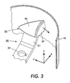
- a blending tool 50 of the present invention is shown in Figure 3 inside of a vessel 10 that is similar to that shown in Figure 1.
- Center shank 51 contains locking fixture 52 at its middle for mounting onto rotating drive shaft 14 (not shown) of the blending machine 2 (not shown).
- an enlarged collision element comprises collision anvil 55 that is proportionately larger than the collision surface of blending tools of the prior art such as that shown in Figure 2.
- enlarged collision surfaces are not practical because a large collision surface creates too much "snow plow" compaction in front of the tool and vortices and relative voids in the wake of the tool.
- a novel feature of the present invention is an enlarged collision element such as collision anvil 55 with cross-sectional perimeters of its leeward surfaces that decrease as such cross-sections are measured closer to the trailing edge of the tool, i.e., its sides and/or top and bottom surfaces tend towards convergence toward the trailing edge.
- This "negative slope" of the leeward surface increases intensity since particles that are pushed upward or sideways upon contact with the collision anvil slide along the leeward slope of the tool to fill its wake as the tool slides through the particle mixture.
- the particle media through which the blending tool moves acts like a fluid as it is mixed by the tool.
- the sloping leeward shape helps minimize voids and turbulence behind the tool. The result is greater particle density available for collision by the next arm of the tool as it sweeps through the blending zone. Greater density of particles leads to greater intensity (collisions/unit of time).
- the rounded shape of the leading profile of collision anvil 55 results in more flow of particles over the tool and less "snow plow" compaction in front of the tool. The result is that for the same consumption of power by the blending machine, it is believed that the present invention allows either greater tool speed or a larger collision plate profile. Either greater speed or larger profile result in greater blend intensity.
- the portion of collision anvil 55 that adds to the profile of the tool can be considered its "leading surface” and is labeled 57 in Figure 3. This is the surface that most directly impacts the particle media.
- the portion of collision anvil 55 to the rear of the leading surface can be considered its “trailing surface” and is labeled 56 in figure 3.
- collision anvil 55 it is also possible to increase the width, or x-axis dimension, of collision anvil 55 to a width that exceeds (even by a factor greater than 1.5 or 2) the height, or y-axis, of center shank 51 in the region of center shank 51 proximate to where collision plate 35 is attached.
- collision anvil 55 it is preferred that collision anvil 55 be hollow or comprised of a relatively thin plate in order to reduce its weight.
- the leading surface of collision anvil 55 or other enlarged collision element of the present invention be less than one-half inch thick and preferably as thin as 3/16 inch thick.
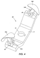
- blending tool 30 comprises a center shank 31 and collision plates 35A and 35B.
- Center shank 31 contains locking fixture 32 at its middle for mounting onto rotating drive shaft 14 (not shown) of the blending machine 2 (not shown).
- Each end of center shank 31 contains a connecting mechanism 33 for rigidly mounting and holding an arm 34.
- Connecting mechanism 33 shown in Figure 4 comprises a simple nut and bolt fastener which compresses together and rigidly positions collision plates 35A and 35B on arms 34A and 34B and on center shank 31, respectively. As will be described more fully below, below, different arrangements for positioning arms 34A and 34B are possible.
- each end region of the center shank 31 could comprise a leading edge flap connected to the center shank by one, two, or more connector mechanisms such that the angle of the flaps could be tilted down or raised much like the leading edge slat of some high speed jets and airplanes
- collision plate 35A mounted at the opposite end of arm 34A from mechanism 33 is an enlarged collision surface formed out of a collision plate 35A.
- Collision plate 35A differs from collision surfaces of the prior art since collision plate 35A is spaced apart and not integrally forged, welded, or otherwise formed as part of center shank 31. Additionally, collision plate 35A presents a substantially larger profile than the profile of center shank 31. Different arrangements for locking collision plate 35A into position are possible. For instance, collision plate 35A could be directly connected to center shank 31 without an arm 34A therebetween or arm 34A could be permanently attached to center shank 31 with a connecting mechanism between the arm 34A and collision plate 35A.
- Arm 34A can assume any number of embodiments, including compound elements, as long as arm 34A functions to position the collision plate apart from center shank 31.
- a preferred embodiment of the present invention uses a connecting mechanism such as mechanism 33 that enables removal and replacement of a collision plate when the collision plate reaches the end of its useful life due to abrasion and wear. Without such removable collision plates, the entire blending tool requires disposal or remanufacturing when the collision plate reaches the end of its useful life.
- Connecting mechanism 33 can assume any number of arrangements long as it allows adjustment of the profile of the tool.
- mechanism 33 allows arm 34A to pivot about the axis of center shank 31.
- mechanism 33 forms an articulator hinge that allows arm 34A to assume any number of angles in relation to center shank 31.
- This articulator hinge is a simple bolt and nut fastener that can be loosened and tightened with standard tools such as socket wrenches. Any number of other articulator hinges are possible as long as they allow arm 34A to pivot when the hinge is loosened and to be held rigidly in place once the hinge is tightened.
- FIG. 5 An example of an alternate embodiment of an articulator hinge 33 is shown in Figure 5.
- the embodiment shown in Figure 5 allows articulation of arm 34 into pre-set positions determined by alignment of bolt 45 (which runs through hole 46 in arm 34) with bored holes 41, 42, 43, and 44 formed in central hub 35.
- the process of articulating the hinge to these pre-set angles is accomplished by the relatively easy loosening and withdrawal bolt 45.
- arm 34 can be repositioned such that bolt 45 aligns with and can be inserted into one of alternate holes 41, 42, 43, and 44.
- arm 34 is again secured in place by refastening bolt 45.
- a leading edge flap could accomplish this purpose.
- a movable collision surface preferably a collision plate, could be connected directly to the center shank without an arm to provide spaced apart separation between the surface and the center shank.
- the preferred embodiment comprises an arm and a spaced apart collision plate as described above in relation to Figures 3 and 4.
- the comparable process for altering the configuration of the blending tool of the present invention is as follows (numbers are in reference to Figures 1 and Figure 3, as applicable): (A) lid 17 is unfastened and opened from the top of vessel 10; (B) blending tool 16 needs to be at least partially cleaned by vacuum and by wiping in the region of articulator hinge 33; (C) articulator hinge 33 is loosened to allow arm 34 (and therefore collision plate 35) to be repositioned; (D) arm 34 is repositioned to the new angle required by the next formulation or product; (D) articulator hinge 33 is re-tightened.
- blending tool 16 of the present invention with its articulator hinge enables significant time, safety, and productivity savings.
- advantages are: 1) elimination of the need for a crane or hoist, thereby saving time (especially if such crane or hoist is not immediately available) as well as a requirement for expensive supplementary equipment such as a hoist; 2) human operators do not need to simultaneously position and fasten during removal of the old tools and placement of the new tool; and 3) cleaning tasks are greatly curtailed and simplified since the entire tool need not be cleaned for replacement, handling, or storage. Cleaning of vessel 10 is also lessened and shaft 14 need not be cleaned at all.
- it is obviously less expensive to be able to use a single flexible blending tool for various formulations and products than to require an inventory of tools which must be substituted each time a formulation or product requires a different tool configuration.
- FIG. 6 shows the various levels of intensity that were obtained with the tool of the present invention as it is reconfigured into different positions.
- Each of the 4 curves shown on Figure 5 show data created during blending of Xerox toner for a Xerox Docucenter 265 multifunctional printer in a Henschel 75-liter blender. Four blends were made, all using the same tool speed.
- the vertical axis measures the specific power of the blending motor (W/lb) which, as discussed above, is considered a good measure of the blend intensity when using an efficient blending tool.
- the horizontal axis measures time of the blend.
- the curve marked with round data points shows the results with arm 34 set at 45 degrees, which angle offered the greatest tool profile for this experiment.
- this curve with square data shows the greatest blend intensity.
- the curve marked with diamond data points shows the results with arm 34 set at 22.5 degrees, while the curve marked with triangular data points shows the results with arm 34 set at 0 degrees. These angles cause decreasing tool profiles and, as expected, decreasing blend intensity that reflects the decreased profiles.
- the curve with square shaped data points shows the results using a standard Henschel blending tool typically used when blending electrophotographic toners (this tool differs from the tool in figure 2).
- the standard tool provided less than 50% of the blend intensity offered by the tool of the present invention at its maximum profile and intensity.
- the blending tool of the present invention includes a collision plate, arcurate surfaces, and articulator hinge.
- the present invention permits higher blend intensity than heretofore possible without snow plow compaction in front of the tool or vortices and voids in the wake of the tool.
- the articulator hinge of the present invention enable a single blending tool of the present invention to assume a wide variety of different configurations, each enabling a different level of blend intensity as may be required by different formulations and products. Together, these improvements of the present invention enable greater blend intensity and overall productivity as well as savings in tool and inventory cost, time, and safety. When thee advantages are applied to the manufacture of toners, substantial cost savings result.
Landscapes
- Chemical & Material Sciences (AREA)
- Chemical Kinetics & Catalysis (AREA)
- Physics & Mathematics (AREA)
- General Physics & Mathematics (AREA)
- Developing Agents For Electrophotography (AREA)
- Mixers Of The Rotary Stirring Type (AREA)
- Processing And Handling Of Plastics And Other Materials For Molding In General (AREA)
Abstract
Description
In a further embodiment the profile of the enlarged collision element is adjustable.
In a further embodiment the height dimension of the enlarged collision element is larger than the depth dimension of the center shank in the end region.
In a further embodiment the enlarged collision element is hollow.
In a further embodiment the drive shaft rotates at least a portion of the enlarged collision element of the blending tool at a speed greater than 50 feet/second.
In a further embodiment the drive shaft rotates at least a portion of the enlarged collision element of the blending tool at a speed greater than greater than 90 feet/second.
In a further embodiment the drive shaft rotates at least a portion of the enlarged collision element of the blending tool at a speed greater than 95 feet/second.
In a further embodiment the step of blending further comprises rotating at least a portion of the enlarged collision element of the blending tool at a speed greater than 50 ft./second.
In a further embodiment the step of blending further comprises rotating at least a portion of the enlarged collision element of the blending tool at a speed greater than 85 ft./second.
In a further embodiment the step of blending further comprises rotating at least a portion of the enlarged collision element of the blending tool at a speed greater than 90 feet/second.
In a further embodiment the step of blending further comprises rotating at least a portion of the enlarged collision element of the blending tool at a speed greater than 95 feet/second.
Claims (10)
- An improved blending tool for rotation in a blending machine, comprising:(a) a center shank having at least one end and a region proximate to the end;(b) an enlarged collision element rigidly fixed during rotation of the tool to the center shank at the end region; and(c) a trailing surface of the enlarged collision element, at least half of said trailing surface being negatively sloped.
- The blending tool of claim 1, further comprising a leading surface having a depth dimension wherein the depth dimension of the leading surface is less than one-half inch.
- The blending tool of claim 1, wherein the sloping portion of the trailing surface is arcurately shaped.
- The blending tool of claim 1, wherein the enlarged collision element has a height dimension and a z-axis and wherein the height along at least a portion of the z-axis of the trailing surface is negatively sloped.
- The blending tool of claim 1, wherein the width of the trailing surface decreases along at least a portion of the z-axis of the trailing surface.
- The blending tool of claim 1, wherein the entire trailing surface has a negative slope.
- The blending tool of claim 1, further comprising an arcurately shaped leading surface of the enlarged collision surface.
- The blending tool of claim 1, wherein the enlarged collision element is spaced apart from the center shank.
- A blending machine, comprising:(a) a housing defining a chamber for holding the media to be blended;(b) a blending tool mounted inside the vessel, said blending tool comprising a center shank having an end and a region proximate to the end; an enlarged collision element rigidly fixed during rotation of the tool to the center shank at the end region; and a trailing surface of the enlarged collision element, at least half of said trailing surface being negatively sloped; and(c) a rotatable drive shaft, connected to the blending tool inside of the vessel, for transmitting rotational motion to the blending tool.
- A method of making toners, comprising(a) melt-mixing a mixture containing toner resin and colorants;(b) reducing the melt-mixture into particles;(c) adding surface additive particles to the mixture of melt-mixture particles; and(d) blending the melt-mixture particles and surface additive particles in a blending machine using a rotating blending tool comprising a center shank having an end and a region proximate to the end; an enlarged collision element rigidly fixed during rotation of the tool to the center shank at the end region; and a trailing surface of the enlarged collision element, at least half of said trailing surface being negatively sloped.
Applications Claiming Priority (2)
| Application Number | Priority Date | Filing Date | Title |
|---|---|---|---|
| US748920 | 2000-12-27 | ||
| US09/748,920 US6523996B2 (en) | 2000-12-27 | 2000-12-27 | Blending tool with an enlarged collision surface for increased blend intensity and method of blending toners |
Publications (3)
| Publication Number | Publication Date |
|---|---|
| EP1219347A2 true EP1219347A2 (en) | 2002-07-03 |
| EP1219347A3 EP1219347A3 (en) | 2003-02-26 |
| EP1219347B1 EP1219347B1 (en) | 2005-10-05 |
Family
ID=25011462
Family Applications (1)
| Application Number | Title | Priority Date | Filing Date |
|---|---|---|---|
| EP01130088A Expired - Lifetime EP1219347B1 (en) | 2000-12-27 | 2001-12-18 | Blending tool with an enlarged collision surface for increased blend intensity and method of blending toners |
Country Status (4)
| Country | Link |
|---|---|
| US (2) | US6523996B2 (en) |
| EP (1) | EP1219347B1 (en) |
| JP (1) | JP4409802B2 (en) |
| DE (1) | DE60113790T2 (en) |
Families Citing this family (14)
| Publication number | Priority date | Publication date | Assignee | Title |
|---|---|---|---|---|
| US6899455B2 (en) * | 2000-12-27 | 2005-05-31 | Xerox Corporation | Blending tool with an adjustable collision profile and method of adjusting the collision profile |
| JP2004337669A (en) * | 2003-05-13 | 2004-12-02 | Shimizu Corp | Stirrer |
| JP4790995B2 (en) * | 2004-03-19 | 2011-10-12 | 株式会社テクノメイト | Slurry dilution device |
| US6991886B2 (en) * | 2004-05-14 | 2006-01-31 | Lexmark International, Inc. | Closed air circulation toner rounding |
| US7235339B2 (en) * | 2004-10-28 | 2007-06-26 | Xerox Corporation | Method of blending toners using a high intensity blending tool with shaped risers for decreased toner agglomeration |
| US7097349B2 (en) * | 2004-10-28 | 2006-08-29 | Xerox Corporation | High intensity blending tool with optimized risers for decreased toner agglomeration |
| US8016479B2 (en) * | 2005-07-25 | 2011-09-13 | Tokyo Printing Ink. Mfg. Co., Ltd. | Dispersing apparatus, dispersion method, and method of manufacturing dispersion |
| US8517184B2 (en) | 2010-09-30 | 2013-08-27 | Baker Hughes Incorporated | Anisotropic filtration media |
| US8673532B2 (en) * | 2012-06-26 | 2014-03-18 | Xerox Corporation | Method of producing dry toner particles having high circularity |
| CA153398S (en) * | 2013-04-15 | 2014-07-11 | Ohg Galletti O M G Srl | Mixing blade for mixing cement |
| US9854813B2 (en) * | 2013-12-30 | 2018-01-02 | Artech S.R.L. | Rotor for alimentary dough kneader machines |
| US9606462B2 (en) * | 2014-08-07 | 2017-03-28 | Canon Kabushiki Kaisha | Toner and method for manufacturing toner |
| JP6863211B2 (en) * | 2017-10-04 | 2021-04-21 | トヨタ自動車株式会社 | Granulation manufacturing method and manufacturing equipment |
| CN112871048A (en) * | 2020-12-28 | 2021-06-01 | 唐山市新型耐火材料厂 | Raw material mixing equipment for furnace core brick production and mixing method thereof |
Family Cites Families (52)
| Publication number | Priority date | Publication date | Assignee | Title |
|---|---|---|---|---|
| US377546A (en) * | 1888-02-07 | Thomas b | ||
| US739422A (en) * | 1902-06-28 | 1903-09-22 | Robert Vinton Jones | Cooking utensil. |
| US1111715A (en) * | 1913-12-30 | 1914-09-22 | H P Hood & Sons | Agitator for milk-tanks and the like. |
| US1536203A (en) * | 1924-01-14 | 1925-05-05 | Nieman A Frydenlund | Paint mixer |
| US2702571A (en) * | 1949-10-04 | 1955-02-22 | Pollard & Johnston | Magnetically actuated food stirring device |
| US3090606A (en) * | 1959-09-11 | 1963-05-21 | Strong Scott Mfg Company | Rotary mixing device |
| US3245663A (en) * | 1964-08-03 | 1966-04-12 | Gen Mills Inc | Agglomerator apparatus and method |
| AT280960B (en) * | 1967-12-14 | 1970-05-11 | Basf Ag | Anchor stirrer |
| US3944493A (en) | 1974-05-16 | 1976-03-16 | Eastman Kodak Company | Electrographic toner and developer composition |
| US4007293A (en) | 1976-03-01 | 1977-02-08 | Xerox Corporation | Mechanically viable developer materials |
| US4338380A (en) | 1976-04-05 | 1982-07-06 | Brunswick Corporation | Method of attaching ceramics to metals for high temperature operation and laminated composite |
| US4079014A (en) | 1976-07-21 | 1978-03-14 | Eastman Kodak Company | Electrographic toner and developer composition containing a 4-aza-1-azoniabicyclo(2.2.2) octane salt as a charge control agent |
| US4054465A (en) | 1976-09-29 | 1977-10-18 | Hercules Incorporated | Lead chromate pigments |
| US4298672A (en) | 1978-06-01 | 1981-11-03 | Xerox Corporation | Toners containing alkyl pyridinium compounds and their hydrates |
| AT363985B (en) * | 1978-09-12 | 1981-09-10 | Krause Ulrich | DEVICE FOR TREATING AND DISPENSING BITUMINOUS SLAVES DURING THE DRIVE THROUGH THE INSTALLATION SITE |
| EP0052298A3 (en) * | 1980-11-18 | 1983-04-06 | Herbert Rieger | Stirring device for fermenting receptacles of grape mash |
| DE3174159D1 (en) | 1981-02-27 | 1986-04-24 | Hodogaya Chemical Co Ltd | Electrophotographic toner |
| US4394430A (en) | 1981-04-14 | 1983-07-19 | Eastman Kodak Company | Electrophotographic dry toner and developer compositions |
| DE8111381U1 (en) * | 1981-04-15 | 1981-11-05 | Fa. Erwin Stelzer, 3530 Warburg | STIRRING DEVICE |
| US4438634A (en) * | 1982-11-05 | 1984-03-27 | General Mills, Inc. | Freeze concentration apparatus |
| US4456382A (en) * | 1983-02-03 | 1984-06-26 | The B. F. Goodrich Company | Agitator hub |
| US4571091A (en) * | 1983-02-22 | 1986-02-18 | J. C. Pardo And Sons | Food process agitator |
| DE3344531C2 (en) * | 1983-12-09 | 1987-03-19 | Gebrüder Lödige, Maschinenbaugesellschaft mbH, 4790 Paderborn | Mixing device |
| US4721394A (en) * | 1985-06-24 | 1988-01-26 | Pro-Quip, Inc. | Mixing blade construction |
| US4790667A (en) * | 1986-09-15 | 1988-12-13 | J. C. Pardo And Sons | Food process agitator |
| JPH0810360B2 (en) | 1987-02-25 | 1996-01-31 | オリヱント化学工業株式会社 | Toner for electrostatic image development |
| US4937439A (en) | 1988-05-13 | 1990-06-26 | National Computer Systems, Inc. | Method and system for creating and scanning a customized survey form |
| US4894308A (en) | 1988-10-17 | 1990-01-16 | Xerox Corporation | Process for preparing electrophotographic toner |
| US4937157A (en) | 1989-08-21 | 1990-06-26 | Xerox Corporation | Toner and developer compositions with charge enhancing additives |
| US5607235A (en) * | 1990-07-13 | 1997-03-04 | Campbell; Craig C. | High speed combined mixing and transport tool |
| US5009510A (en) * | 1990-09-27 | 1991-04-23 | J. C. Pardo And Sons | Scraper mounting arrangement for food process agitators |
| DE4221315B4 (en) * | 1992-06-29 | 2009-01-08 | Richard Frisse Gmbh Maschinenfabrik | Conche |
| JPH0619821U (en) * | 1992-08-07 | 1994-03-15 | 佐竹化学機械工業株式会社 | Stirring blade |
| US5370962A (en) | 1993-03-01 | 1994-12-06 | Xerox Corporation | Toner compositions with blend compatibility additives |
| US5785424A (en) * | 1993-04-30 | 1998-07-28 | Kansai Chemical Engineering Co. Ltd. | Agitator blade having agitators with open first and second ends and inner fabrics therein |
| DE4344995A1 (en) * | 1993-12-30 | 1995-07-06 | Loedige Maschbau Gmbh Geb | Mixing tool |
| US5393139A (en) * | 1994-07-26 | 1995-02-28 | Mixer Systems, Inc. | Mixing blade mounting assembly |
| US5624079A (en) | 1995-03-10 | 1997-04-29 | Xerox Corporation | Injection blending of toner during grinding |
| JPH09114135A (en) * | 1995-10-16 | 1997-05-02 | Dainippon Ink & Chem Inc | Manufacturing method of electrophotographic toner |
| JP2931256B2 (en) * | 1995-11-01 | 1999-08-09 | 神鋼パンテツク株式会社 | Axial flow type stirring blade |
| US5716751A (en) | 1996-04-01 | 1998-02-10 | Xerox Corporation | Toner particle comminution and surface treatment processes |
| DE19711019A1 (en) * | 1997-03-17 | 1998-09-24 | Basf Ag | Stirrer with variably adjustable stirring elements for polymerization reactors |
| DE69801458T2 (en) * | 1997-04-04 | 2002-04-18 | Canon K.K., Tokio/Tokyo | Toner for image formation, image forming processes, and heat fixing processes |
| US5874034A (en) | 1997-04-14 | 1999-02-23 | Xerox Corporation | Swell reducing extrusion die |
| US5763132A (en) | 1997-04-17 | 1998-06-09 | Xerox Corporation | Toner compositions |
| US5981269A (en) * | 1997-08-20 | 1999-11-09 | Park; Joon | Apparatus for fermenting and composting food waste |
| DK0916390T3 (en) * | 1997-11-14 | 2003-01-06 | Kansai Chem Eng | Method of ejecting liquid and device for carrying out the method |
| US5888691A (en) * | 1997-11-24 | 1999-03-30 | Xerox Corporation | Process for producing toner |
| US5869216A (en) * | 1998-01-13 | 1999-02-09 | Xerox Corporation | Toner processes |
| US5998079A (en) | 1998-05-07 | 1999-12-07 | International Communication Materials, Inc. | Color toner |
| CA2298879C (en) * | 1999-02-22 | 2004-09-14 | Hideo Noda | Liquid ejection apparatus and liquid ejection method |
| IT1310583B1 (en) * | 1999-04-30 | 2002-02-19 | Wam Spa | MIXER DEVICE, IN PARTICULAR FOR INCONERENT MATERIAL, GRANULES OR POWDER, OR PASTY. |
-
2000
- 2000-12-27 US US09/748,920 patent/US6523996B2/en not_active Expired - Lifetime
-
2001
- 2001-12-18 EP EP01130088A patent/EP1219347B1/en not_active Expired - Lifetime
- 2001-12-18 DE DE60113790T patent/DE60113790T2/en not_active Expired - Lifetime
- 2001-12-26 JP JP2001394345A patent/JP4409802B2/en not_active Expired - Fee Related
-
2002
- 2002-06-14 US US10/173,193 patent/US6586150B2/en not_active Expired - Lifetime
Also Published As
| Publication number | Publication date |
|---|---|
| DE60113790T2 (en) | 2006-06-08 |
| US20020155371A1 (en) | 2002-10-24 |
| JP4409802B2 (en) | 2010-02-03 |
| EP1219347B1 (en) | 2005-10-05 |
| US6586150B2 (en) | 2003-07-01 |
| JP2002239363A (en) | 2002-08-27 |
| US20020080679A1 (en) | 2002-06-27 |
| US6523996B2 (en) | 2003-02-25 |
| DE60113790D1 (en) | 2006-02-16 |
| EP1219347A3 (en) | 2003-02-26 |
Similar Documents
| Publication | Publication Date | Title |
|---|---|---|
| USRE41652E1 (en) | Toner with increased amount of surface additives and increased surface additive adhesion | |
| EP1219347B1 (en) | Blending tool with an enlarged collision surface for increased blend intensity and method of blending toners | |
| CA2399688C (en) | An improved high intensity blending tool with optimized risers for increased intensity when blending toners | |
| EP1288725B1 (en) | Toner and process for producing said toner | |
| US6899455B2 (en) | Blending tool with an adjustable collision profile and method of adjusting the collision profile | |
| KR0152066B1 (en) | Method for preparing colored powder coating composition and powder coating method using same | |
| US7097349B2 (en) | High intensity blending tool with optimized risers for decreased toner agglomeration | |
| KR100238614B1 (en) | Pneumatic impact pulverizer and process for producing toner | |
| US7235339B2 (en) | Method of blending toners using a high intensity blending tool with shaped risers for decreased toner agglomeration | |
| JPH09150048A (en) | Mixing apparatus for powder and granular material and method for producing toner | |
| JP4268331B2 (en) | Toner production method | |
| JP2004010778A (en) | Easily dispersible pigment composition and method for producing the same | |
| JPH09192524A (en) | Pneumatic actuation type nozzle plug | |
| CN216137148U (en) | Two-component coating stirrer | |
| CN213611727U (en) | Water paint dull polish machine | |
| JP2001179067A (en) | Dispersion equipment | |
| JPH0148057B2 (en) | ||
| KR20060051083A (en) | Pigment Manufacturing Method | |
| JP2003233218A (en) | Manufacturing method of toner |
Legal Events
| Date | Code | Title | Description |
|---|---|---|---|
| PUAI | Public reference made under article 153(3) epc to a published international application that has entered the european phase |
Free format text: ORIGINAL CODE: 0009012 |
|
| AK | Designated contracting states |
Kind code of ref document: A2 Designated state(s): AT BE CH CY DE DK ES FI FR GB GR IE IT LI LU MC NL PT SE TR |
|
| AX | Request for extension of the european patent |
Free format text: AL;LT;LV;MK;RO;SI |
|
| PUAL | Search report despatched |
Free format text: ORIGINAL CODE: 0009013 |
|
| AK | Designated contracting states |
Kind code of ref document: A3 Designated state(s): AT BE CH CY DE DK ES FI FR GB GR IE IT LI LU MC NL PT SE TR |
|
| AX | Request for extension of the european patent |
Extension state: AL LT LV MK RO SI |
|
| 17P | Request for examination filed |
Effective date: 20030826 |
|
| AKX | Designation fees paid |
Designated state(s): DE FR GB |
|
| 17Q | First examination report despatched |
Effective date: 20041102 |
|
| GRAP | Despatch of communication of intention to grant a patent |
Free format text: ORIGINAL CODE: EPIDOSNIGR1 |
|
| GRAS | Grant fee paid |
Free format text: ORIGINAL CODE: EPIDOSNIGR3 |
|
| GRAA | (expected) grant |
Free format text: ORIGINAL CODE: 0009210 |
|
| AK | Designated contracting states |
Kind code of ref document: B1 Designated state(s): DE FR GB |
|
| REG | Reference to a national code |
Ref country code: GB Ref legal event code: FG4D |
|
| REF | Corresponds to: |
Ref document number: 60113790 Country of ref document: DE Date of ref document: 20060216 Kind code of ref document: P |
|
| ET | Fr: translation filed | ||
| PLBE | No opposition filed within time limit |
Free format text: ORIGINAL CODE: 0009261 |
|
| STAA | Information on the status of an ep patent application or granted ep patent |
Free format text: STATUS: NO OPPOSITION FILED WITHIN TIME LIMIT |
|
| 26N | No opposition filed |
Effective date: 20060706 |
|
| REG | Reference to a national code |
Ref country code: FR Ref legal event code: PLFP Year of fee payment: 15 |
|
| PGFP | Annual fee paid to national office [announced via postgrant information from national office to epo] |
Ref country code: DE Payment date: 20151119 Year of fee payment: 15 Ref country code: GB Payment date: 20151125 Year of fee payment: 15 |
|
| PGFP | Annual fee paid to national office [announced via postgrant information from national office to epo] |
Ref country code: FR Payment date: 20151123 Year of fee payment: 15 |
|
| REG | Reference to a national code |
Ref country code: DE Ref legal event code: R119 Ref document number: 60113790 Country of ref document: DE |
|
| GBPC | Gb: european patent ceased through non-payment of renewal fee |
Effective date: 20161218 |
|
| REG | Reference to a national code |
Ref country code: FR Ref legal event code: ST Effective date: 20170831 |
|
| PG25 | Lapsed in a contracting state [announced via postgrant information from national office to epo] |
Ref country code: FR Free format text: LAPSE BECAUSE OF NON-PAYMENT OF DUE FEES Effective date: 20170102 |
|
| PG25 | Lapsed in a contracting state [announced via postgrant information from national office to epo] |
Ref country code: DE Free format text: LAPSE BECAUSE OF NON-PAYMENT OF DUE FEES Effective date: 20170701 Ref country code: GB Free format text: LAPSE BECAUSE OF NON-PAYMENT OF DUE FEES Effective date: 20161218 |