EP1218956B1 - Battery box - Google Patents
Battery box Download PDFInfo
- Publication number
- EP1218956B1 EP1218956B1 EP00960262A EP00960262A EP1218956B1 EP 1218956 B1 EP1218956 B1 EP 1218956B1 EP 00960262 A EP00960262 A EP 00960262A EP 00960262 A EP00960262 A EP 00960262A EP 1218956 B1 EP1218956 B1 EP 1218956B1
- Authority
- EP
- European Patent Office
- Prior art keywords
- lithium battery
- battery box
- rechargeable lithium
- foil layer
- oxygen
- Prior art date
- Legal status (The legal status is an assumption and is not a legal conclusion. Google has not performed a legal analysis and makes no representation as to the accuracy of the status listed.)
- Expired - Lifetime
Links
- 229910052744 lithium Inorganic materials 0.000 claims abstract description 43
- WHXSMMKQMYFTQS-UHFFFAOYSA-N Lithium Chemical compound [Li] WHXSMMKQMYFTQS-UHFFFAOYSA-N 0.000 claims abstract description 41
- QVGXLLKOCUKJST-UHFFFAOYSA-N atomic oxygen Chemical compound [O] QVGXLLKOCUKJST-UHFFFAOYSA-N 0.000 claims abstract description 18
- 239000001301 oxygen Substances 0.000 claims abstract description 18
- 229910052760 oxygen Inorganic materials 0.000 claims abstract description 18
- 239000011244 liquid electrolyte Substances 0.000 claims abstract description 8
- 239000002650 laminated plastic Substances 0.000 claims abstract description 6
- MYMOFIZGZYHOMD-UHFFFAOYSA-N Dioxygen Chemical compound O=O MYMOFIZGZYHOMD-UHFFFAOYSA-N 0.000 claims abstract description 5
- 229910001882 dioxygen Inorganic materials 0.000 claims abstract description 5
- 239000011888 foil Substances 0.000 claims description 38
- 239000011248 coating agent Substances 0.000 claims description 7
- 238000000576 coating method Methods 0.000 claims description 7
- 239000003792 electrolyte Substances 0.000 claims description 7
- 239000000758 substrate Substances 0.000 claims description 7
- 239000004020 conductor Substances 0.000 claims description 5
- 239000000463 material Substances 0.000 claims description 5
- 238000004382 potting Methods 0.000 claims description 3
- 238000007599 discharging Methods 0.000 claims description 2
- 238000005476 soldering Methods 0.000 claims description 2
- 239000007788 liquid Substances 0.000 claims 1
- 229910052751 metal Inorganic materials 0.000 abstract description 7
- 239000002184 metal Substances 0.000 abstract description 7
- 239000007789 gas Substances 0.000 abstract description 3
- 229910001416 lithium ion Inorganic materials 0.000 description 5
- RYGMFSIKBFXOCR-UHFFFAOYSA-N Copper Chemical compound [Cu] RYGMFSIKBFXOCR-UHFFFAOYSA-N 0.000 description 4
- 229910052802 copper Inorganic materials 0.000 description 4
- 239000010949 copper Substances 0.000 description 4
- 238000007789 sealing Methods 0.000 description 3
- HBBGRARXTFLTSG-UHFFFAOYSA-N Lithium ion Chemical compound [Li+] HBBGRARXTFLTSG-UHFFFAOYSA-N 0.000 description 2
- 239000000853 adhesive Substances 0.000 description 2
- 230000001070 adhesive effect Effects 0.000 description 2
- 238000000034 method Methods 0.000 description 2
- 238000004806 packaging method and process Methods 0.000 description 2
- 229910000679 solder Inorganic materials 0.000 description 2
- 229920001187 thermosetting polymer Polymers 0.000 description 2
- ATJFFYVFTNAWJD-UHFFFAOYSA-N Tin Chemical compound [Sn] ATJFFYVFTNAWJD-UHFFFAOYSA-N 0.000 description 1
- 230000001154 acute effect Effects 0.000 description 1
- 229910045601 alloy Inorganic materials 0.000 description 1
- 239000000956 alloy Substances 0.000 description 1
- 229910052782 aluminium Inorganic materials 0.000 description 1
- XAGFODPZIPBFFR-UHFFFAOYSA-N aluminium Chemical compound [Al] XAGFODPZIPBFFR-UHFFFAOYSA-N 0.000 description 1
- 238000006243 chemical reaction Methods 0.000 description 1
- 238000004891 communication Methods 0.000 description 1
- 238000005530 etching Methods 0.000 description 1
- 230000014509 gene expression Effects 0.000 description 1
- -1 however Substances 0.000 description 1
- 239000007769 metal material Substances 0.000 description 1
- 230000005012 migration Effects 0.000 description 1
- 238000013508 migration Methods 0.000 description 1
- 238000012986 modification Methods 0.000 description 1
- 230000004048 modification Effects 0.000 description 1
- 229920006254 polymer film Polymers 0.000 description 1
- XLYOFNOQVPJJNP-UHFFFAOYSA-N water Substances O XLYOFNOQVPJJNP-UHFFFAOYSA-N 0.000 description 1
Images



Classifications
-
- H—ELECTRICITY
- H01—ELECTRIC ELEMENTS
- H01M—PROCESSES OR MEANS, e.g. BATTERIES, FOR THE DIRECT CONVERSION OF CHEMICAL ENERGY INTO ELECTRICAL ENERGY
- H01M50/00—Constructional details or processes of manufacture of the non-active parts of electrochemical cells other than fuel cells, e.g. hybrid cells
- H01M50/10—Primary casings; Jackets or wrappings
- H01M50/14—Primary casings; Jackets or wrappings for protecting against damage caused by external factors
- H01M50/141—Primary casings; Jackets or wrappings for protecting against damage caused by external factors for protecting against humidity
-
- H—ELECTRICITY
- H01—ELECTRIC ELEMENTS
- H01M—PROCESSES OR MEANS, e.g. BATTERIES, FOR THE DIRECT CONVERSION OF CHEMICAL ENERGY INTO ELECTRICAL ENERGY
- H01M50/00—Constructional details or processes of manufacture of the non-active parts of electrochemical cells other than fuel cells, e.g. hybrid cells
- H01M50/10—Primary casings; Jackets or wrappings
- H01M50/102—Primary casings; Jackets or wrappings characterised by their shape or physical structure
- H01M50/103—Primary casings; Jackets or wrappings characterised by their shape or physical structure prismatic or rectangular
-
- H—ELECTRICITY
- H01—ELECTRIC ELEMENTS
- H01M—PROCESSES OR MEANS, e.g. BATTERIES, FOR THE DIRECT CONVERSION OF CHEMICAL ENERGY INTO ELECTRICAL ENERGY
- H01M50/00—Constructional details or processes of manufacture of the non-active parts of electrochemical cells other than fuel cells, e.g. hybrid cells
- H01M50/50—Current conducting connections for cells or batteries
- H01M50/543—Terminals
- H01M50/547—Terminals characterised by the disposition of the terminals on the cells
- H01M50/55—Terminals characterised by the disposition of the terminals on the cells on the same side of the cell
-
- H—ELECTRICITY
- H01—ELECTRIC ELEMENTS
- H01M—PROCESSES OR MEANS, e.g. BATTERIES, FOR THE DIRECT CONVERSION OF CHEMICAL ENERGY INTO ELECTRICAL ENERGY
- H01M50/00—Constructional details or processes of manufacture of the non-active parts of electrochemical cells other than fuel cells, e.g. hybrid cells
- H01M50/50—Current conducting connections for cells or batteries
- H01M50/543—Terminals
- H01M50/552—Terminals characterised by their shape
- H01M50/553—Terminals adapted for prismatic, pouch or rectangular cells
-
- H—ELECTRICITY
- H01—ELECTRIC ELEMENTS
- H01M—PROCESSES OR MEANS, e.g. BATTERIES, FOR THE DIRECT CONVERSION OF CHEMICAL ENERGY INTO ELECTRICAL ENERGY
- H01M10/00—Secondary cells; Manufacture thereof
- H01M10/05—Accumulators with non-aqueous electrolyte
- H01M10/052—Li-accumulators
-
- Y—GENERAL TAGGING OF NEW TECHNOLOGICAL DEVELOPMENTS; GENERAL TAGGING OF CROSS-SECTIONAL TECHNOLOGIES SPANNING OVER SEVERAL SECTIONS OF THE IPC; TECHNICAL SUBJECTS COVERED BY FORMER USPC CROSS-REFERENCE ART COLLECTIONS [XRACs] AND DIGESTS
- Y02—TECHNOLOGIES OR APPLICATIONS FOR MITIGATION OR ADAPTATION AGAINST CLIMATE CHANGE
- Y02E—REDUCTION OF GREENHOUSE GAS [GHG] EMISSIONS, RELATED TO ENERGY GENERATION, TRANSMISSION OR DISTRIBUTION
- Y02E60/00—Enabling technologies; Technologies with a potential or indirect contribution to GHG emissions mitigation
- Y02E60/10—Energy storage using batteries
-
- Y—GENERAL TAGGING OF NEW TECHNOLOGICAL DEVELOPMENTS; GENERAL TAGGING OF CROSS-SECTIONAL TECHNOLOGIES SPANNING OVER SEVERAL SECTIONS OF THE IPC; TECHNICAL SUBJECTS COVERED BY FORMER USPC CROSS-REFERENCE ART COLLECTIONS [XRACs] AND DIGESTS
- Y02—TECHNOLOGIES OR APPLICATIONS FOR MITIGATION OR ADAPTATION AGAINST CLIMATE CHANGE
- Y02P—CLIMATE CHANGE MITIGATION TECHNOLOGIES IN THE PRODUCTION OR PROCESSING OF GOODS
- Y02P70/00—Climate change mitigation technologies in the production process for final industrial or consumer products
- Y02P70/50—Manufacturing or production processes characterised by the final manufactured product
Definitions
- This invention relates to the structure and assembly of rechargeable lithium batteries from rechargeable lithium battery cells.
- Rechargeable lithium battery cells are generally packaged as individual cell units in either cylindrical metal tubes or foil pouches. Each cell unit contains positive and negative electrodes, electrolyte and positive and negative current collectors. The current collectors must be accessible from outside of the package to enable electrical connection thereto.
- the cell Because of the materials used in a rechargeable lithium battery cell, the cell must be protected against moisture and oxygen ingress to avoid undesirable reactions. Furthermore, where liquid electrolytes are used, the packaging must also be capable of preventing liquid electrolyte egress. Cell seals are typically bulky and heavy, often representing in excess of 10% of cell weight and volume.
- a plurality of lithium battery cells are typically enclosed in a plastic battery box with appropriate cell interconnections therebetween.
- the battery boxes primarily provide a structure for housing the battery cells. As the cells are themselves sealed against oxygen and moisture ingress and liquid electrolyte egress, it has not been found necessary or cost efficient in the past to provide a hermetically sealed battery box for lithium-ion cells.
- foil In "foil" pouch packaged lithium battery cells, the use of a polymeric coated foil gives rise to a need to adequately ensure that leads from the current collectors don't contact the foil material and thereby "short-out". This problem is particularly acute along the outer edges of the foil covering which have usually been cut to size. thereby exposing the electrically conductive foil in close proximity to the leads, creating a need for shielding of the leads in this area.
- a battery box sealable against moisture and oxygen ingress and liquid electrolyte egress.
- the battery box includes a first end, a second end opposite the first end, and side walls extending between the first and second ends to define a chamber for housing a number of rechargeable lithium battery cells.
- the first end and the side walls are metallic and have a substantially moisture and oxygen gas impervious joint between them.
- the second end is of a metal plastic laminate joinable to the side walls by a joining medium to form a substantially moisture and oxygen impervious joint therebetween.
- the second end has electrical connectors extending through it which enable substantially moisture and gas impervious connection to be made between current collectors of the rechargeable lithium battery cells and the outside of the battery box.
- a rechargeable lithium battery according to the present invention is generally illustrated by reference 10 in Figure 2.
- the battery 10 comprises three rechargeable lithium battery cells 12 stacked in a battery box 14 having a first end 16, a second end 18 and side walls 20. Although three lithium-ion cells are shown, the actual number may vary depending on the application.
- Figure 1 shows a typical foil wrapped lithium battery cell 12.
- the cell contains a positive electrode 22, a negative electrode 24, an electrolyte 26 and positive and negative “leads” or “current collectors”, 28 and 30 respectively, enclosed in a pouch 32.
- the leads 28 and 30 provide electrical communication between the positive and negative electrodes 22 and 24 15 respectively and the outside of the pouch 32.
- Rechargeable lithium batteries usually include a lithium-ion containing negative electrode, but may instead have a lithium metal or lithium negative alloy. Nevertheless, insofar as the teachings of this specification would apply to either a lithium metal or a lithium-ion containing negative electrode, the expressions "lithium battery cell” and “lithium battery” are intended to cover both variants.
- the pouch 32 may be made from a suitable metal foil with a plastic laminate coating on at least the inside surface and preferably on both surfaces.
- Aluminum is the usually selected metal foil, however, copper may also be used or any other metal that can be formed to a suitable thickness and which exhibits good moisture and oxygen impermeability.
- a foil pouch requires a relatively thick foil to be sufficiently moisture and gas impermeable and the resulting foil package can represent up to 10% of cell weight and volume. Furthermore, the foil is prone to breaking in the comers if one tries to cram the lithium battery cell 12 into a tightly fitting container.
- the battery box 14 performs the function of sealing against moisture and oxygen ingress, unlike prior art battery boxes which basically acted as a holder for individually sealed cells.
- This allows the use of thinner and lighter pouches 32 and the possibility of non-metallic pouches 32, for example, of a polymer film.
- packaging can basically be eliminated in favour of merely electrically isolating the individual lithium battery cells 12 from each other and the battery box 14.
- An advantage of non-metallic pouches is the avoidance of the risk of a short circuit between the current collectors or leads 28 and 30 and exposed metal foil along the edge of the pouch 32.
- the pouch 32 merely has to be substantially impervious to electrolyte egress, which may be a lesser requirement to meet than oxygen or moisture ingress.
- the pouch 32 may therefore be much thinner and also less prone to leaking when "scrunched" 20 into a compact box than would be the case with a typical foil pouch.
- moisture it is intended herein to refer primarily to water, particularly in vapour form.
- the battery box 10 has a first end 16 and side walls 20 of a metallic material such as tin.
- the first end 16 may be integral with the side walls 20, however, it may be more convenient for assembly to have a separate first end 16 joinable to the side walls 20 by any suitable means, such as soldering or possibly a polymeric adhesive.
- the side walls 20 illustrated are in a generally rectangular configuration. This is not a requirement, but merely suits the shape of the lithium battery cells 12 illustrated. Other shapes may be selected as required.
- the lithium battery cells 12 may be interconnected by interconnecting leads 34 in series or parallel as required.
- Principal output leads 36 connect the non-interconnected current collectors of opposite polarity on the first and last lithium battery cells 12 to electrical connectors 40 extending through the second end 18 of the battery box 14.
- Further output leads 38 connect the interconnecting leads 34 to further electrical connectors 40 extending through the second end 18. It is not necessary to make all of the cell interconnections internally as separate electrical connectors 40 for charge or discharge purposes may be provided for each positive and negative current collector, 28 and 30 respectively, and cell interconnections could then be made externally if desired.
- the second end 18 of the battery box 14 must be sealably connectable to the side walls 20 while providing separate electrical connections through to the outside of the box at electrical connectors 40.
- a metallic second end 18 would be preferred, however, this would require a suitably insulating sealing arrangement to provide discrete electrical connectors 40. It has been found that a suitable degree of moisture and air impermeability is obtained from a copper/thermoset/copper printed circuit board with suitable modifications in the region ofthe electrical connectors 40 as described below.
- Figure 3 illustrates an inner face 42 which has an inner foil layer 44, typically of copper, laminated over a non-conductive substantially rigid substrate 46 such as a typical thermoset plastic printed circuit board substrate.
- the inner foil layer 44 extends substantially over the entire inner face 42, but for circular breaches 48 extending about the electrical connectors 40 to create discrete electrically isolated connector areas 50.
- An insulating coating 52 such as a plastic laminate, extends over the inner foil layer 44 leaving an exposed edge 54 extending about the perimeter of the inner face 42 and exposed areas which act as the electrical connectors 40.
- the exposed edge 54 enables a solder connection to be made between the second end 18 and the side walls 20.
- a substantially moisture and oxygen impervious overlay 56 is placed over the breaches 48.
- the overlay 56 may be of an adhesive foil and may have a non-conductive polymeric coating facing into the battery box 14.
- Each overlay 56 has a circular opening 58 extending through it and spaced apart from the associated electrical connector 40 to expose the connector 40 and avoid electrical conductivity therebetween.
- the electrical connectors 40 may be through plated holes extending through the substrate 46 between the adjacent portions of the inner foil layer 44 and an outer foil layer 64.
- the electrical connectors 40 provide electrical continuity between the conductive layers inside and the outside of the batter box 14. As such, any desired electrical connections could be made directly to the electrical connectors 40. Nevertheless, it generally proves more convenient to provide electrical terminals along an edge of the strip, such as battery terminals 60 in Figures 3 and 5 which may also be through plated holes.
- the battery terminals 60 are electrically connected to respective of the electrical connectors 40 by conductor strips 62.
- the conductor strips 62 can be formed in the outer foil layer 64 on an outer face of the second end 18 by etching away portions of the outer foil layer 64, leaving discrete conductor strips 62.
- An outer insulating coating 66 such as a plastic laminate, may be applied over the outer foil layer 64 to avoid undesirable electrical contact with the outer foil layer 64.
- the battery box 14 may optionally contain electronic circuitry, such as schematically illustrated at reference 68 in Figure 2, connected to the lithium battery cells 12 to monitor the battery charging and discharging process.
- the electronic circuitry 68 may be externally connected to the battery terminals 60 and not necessarily part of the battery 10.
- a sealable port 70 may be provided to enable evacuation and sealing or backfilling (wholly or partly) with an appropriate potting material.
- the sealable port 70 may be a through plated opening sealable by solder as with the electrical connectors 40.
Landscapes
- Chemical & Material Sciences (AREA)
- Chemical Kinetics & Catalysis (AREA)
- Electrochemistry (AREA)
- General Chemical & Material Sciences (AREA)
- Sealing Battery Cases Or Jackets (AREA)
- Connection Of Batteries Or Terminals (AREA)
- Battery Mounting, Suspending (AREA)
- Secondary Cells (AREA)
Abstract
Description
- This invention relates to the structure and assembly of rechargeable lithium batteries from rechargeable lithium battery cells.
- Rechargeable lithium battery cells are generally packaged as individual cell units in either cylindrical metal tubes or foil pouches. Each cell unit contains positive and negative electrodes, electrolyte and positive and negative current collectors. The current collectors must be accessible from outside of the package to enable electrical connection thereto.
- Because of the materials used in a rechargeable lithium battery cell, the cell must be protected against moisture and oxygen ingress to avoid undesirable reactions. Furthermore, where liquid electrolytes are used, the packaging must also be capable of preventing liquid electrolyte egress. Cell seals are typically bulky and heavy, often representing in excess of 10% of cell weight and volume.
- In order to meet various reserve capacity and voltage requirements, a plurality of lithium battery cells are typically enclosed in a plastic battery box with appropriate cell interconnections therebetween. The battery boxes primarily provide a structure for housing the battery cells. As the cells are themselves sealed against oxygen and moisture ingress and liquid electrolyte egress, it has not been found necessary or cost efficient in the past to provide a hermetically sealed battery box for lithium-ion cells.
- In "foil" pouch packaged lithium battery cells, the use of a polymeric coated foil gives rise to a need to adequately ensure that leads from the current collectors don't contact the foil material and thereby "short-out". This problem is particularly acute along the outer edges of the foil covering which have usually been cut to size. thereby exposing the electrically conductive foil in close proximity to the leads, creating a need for shielding of the leads in this area.
- It is an object of the present invention to provide a battery box for rechargeable lithium battery cells which is mechanically strong and hermetically sealable.
- A battery box sealable against moisture and oxygen ingress and liquid electrolyte egress. The battery box includes a first end, a second end opposite the first end, and side walls extending between the first and second ends to define a chamber for housing a number of rechargeable lithium battery cells.
- The first end and the side walls are metallic and have a substantially moisture and oxygen gas impervious joint between them.
- The second end is of a metal plastic laminate joinable to the side walls by a joining medium to form a substantially moisture and oxygen impervious joint therebetween. The second end has electrical connectors extending through it which enable substantially moisture and gas impervious connection to be made between current collectors of the rechargeable lithium battery cells and the outside of the battery box.
- Preferred embodiments of the invention are described below with reference to the accompanying drawings in which:
- Figure 1 is a perspective view, partially cut away of a prior an rechargeable lithium battery cell;
- Figure 2 is an exploded perspective view of a rechargeable lithium battery according to the present invention;
- Figure 3 is a top plan view of a second end of a battery box according to the present invention;
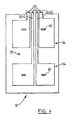
- Figure 4 is a bottom plan view of a second end of a battery box according to the present invention;
- Figure 5 is a section on line 5-5 of Figure 3, showing only the sectioned surface.
-
- A rechargeable lithium battery according to the present invention is generally illustrated by
reference 10 in Figure 2. Thebattery 10 comprises three rechargeablelithium battery cells 12 stacked in abattery box 14 having afirst end 16, asecond end 18 andside walls 20. Although three lithium-ion cells are shown, the actual number may vary depending on the application. - Figure 1 shows a typical foil wrapped
lithium battery cell 12. The cell contains apositive electrode 22, a negative electrode 24, an electrolyte 26 and positive and negative "leads" or "current collectors", 28 and 30 respectively, enclosed in apouch 32. The leads 28 and 30 provide electrical communication between the positive andnegative electrodes 22 and 24 15 respectively and the outside of thepouch 32. - Rechargeable lithium batteries usually include a lithium-ion containing negative electrode, but may instead have a lithium metal or lithium negative alloy. Nevertheless, insofar as the teachings of this specification would apply to either a lithium metal or a lithium-ion containing negative electrode, the expressions "lithium battery cell" and "lithium battery" are intended to cover both variants.
- As discussed in the background above, it is necessary to prevent moisture and oxygen contact with the inside of the lithium battery cell. In the past, this has been achieved on a cell by cell basis by encapsulating each lithium-ion cell in a substantially moisture and oxygen impervious, i.e. "hermetically sealed" shell. For example, in the case of the prior art
lithium battery cell 12 in Figure 1, thepouch 32 may be made from a suitable metal foil with a plastic laminate coating on at least the inside surface and preferably on both surfaces. Aluminum is the usually selected metal foil, however, copper may also be used or any other metal that can be formed to a suitable thickness and which exhibits good moisture and oxygen impermeability. - Unfortunately, a foil pouch requires a relatively thick foil to be sufficiently moisture and gas impermeable and the resulting foil package can represent up to 10% of cell weight and volume. Furthermore, the foil is prone to breaking in the comers if one tries to cram the
lithium battery cell 12 into a tightly fitting container. - According to the present invention, the
battery box 14 performs the function of sealing against moisture and oxygen ingress, unlike prior art battery boxes which basically acted as a holder for individually sealed cells. This allows the use of thinner andlighter pouches 32 and the possibility ofnon-metallic pouches 32, for example, of a polymer film. In the case of non-liquid electrolytes, packaging can basically be eliminated in favour of merely electrically isolating the individuallithium battery cells 12 from each other and thebattery box 14. An advantage of non-metallic pouches is the avoidance of the risk of a short circuit between the current collectors or leads 28 and 30 and exposed metal foil along the edge of thepouch 32. - Where liquid electrolytes 26 are used, the
pouch 32 merely has to be substantially impervious to electrolyte egress, which may be a lesser requirement to meet than oxygen or moisture ingress. Thepouch 32 may therefore be much thinner and also less prone to leaking when "scrunched" 20 into a compact box than would be the case with a typical foil pouch. For the sake of clarity, it should be understood that by "moisture", it is intended herein to refer primarily to water, particularly in vapour form. - The
battery box 10 has afirst end 16 andside walls 20 of a metallic material such as tin. Thefirst end 16 may be integral with theside walls 20, however, it may be more convenient for assembly to have a separatefirst end 16 joinable to theside walls 20 by any suitable means, such as soldering or possibly a polymeric adhesive. - The
side walls 20 illustrated are in a generally rectangular configuration. This is not a requirement, but merely suits the shape of thelithium battery cells 12 illustrated. Other shapes may be selected as required. - The
lithium battery cells 12 may be interconnected by interconnecting leads 34 in series or parallel as required. Principal output leads 36 connect the non-interconnected current collectors of opposite polarity on the first and lastlithium battery cells 12 toelectrical connectors 40 extending through thesecond end 18 of thebattery box 14. Further output leads 38 connect the interconnecting leads 34 to furtherelectrical connectors 40 extending through thesecond end 18. It is not necessary to make all of the cell interconnections internally as separateelectrical connectors 40 for charge or discharge purposes may be provided for each positive and negative current collector, 28 and 30 respectively, and cell interconnections could then be made externally if desired. - The
second end 18 of thebattery box 14 must be sealably connectable to theside walls 20 while providing separate electrical connections through to the outside of the box atelectrical connectors 40. - From the standpoint of oxygen and moisture impermeability, a metallic
second end 18 would be preferred, however, this would require a suitably insulating sealing arrangement to provide discreteelectrical connectors 40. It has been found that a suitable degree of moisture and air impermeability is obtained from a copper/thermoset/copper printed circuit board with suitable modifications in the region oftheelectrical connectors 40 as described below. - Reference is now made to Figures 3, 4 and 5 which illustrate the
second end 18 in detail. Figure 3 illustrates aninner face 42 which has aninner foil layer 44, typically of copper, laminated over a non-conductive substantiallyrigid substrate 46 such as a typical thermoset plastic printed circuit board substrate. Theinner foil layer 44 extends substantially over the entireinner face 42, but forcircular breaches 48 extending about theelectrical connectors 40 to create discrete electricallyisolated connector areas 50. - An insulating
coating 52, such as a plastic laminate, extends over theinner foil layer 44 leaving an exposededge 54 extending about the perimeter of theinner face 42 and exposed areas which act as theelectrical connectors 40. The exposededge 54 enables a solder connection to be made between thesecond end 18 and theside walls 20. - To avoid oxygen and moisture migration through the
substrate 46 at thebreaches 48, a substantially moisture and oxygenimpervious overlay 56 is placed over thebreaches 48. Theoverlay 56 may be of an adhesive foil and may have a non-conductive polymeric coating facing into thebattery box 14. Eachoverlay 56 has acircular opening 58 extending through it and spaced apart from the associatedelectrical connector 40 to expose theconnector 40 and avoid electrical conductivity therebetween. - The
electrical connectors 40 may be through plated holes extending through thesubstrate 46 between the adjacent portions of theinner foil layer 44 and anouter foil layer 64. Theelectrical connectors 40 provide electrical continuity between the conductive layers inside and the outside of thebatter box 14. As such, any desired electrical connections could be made directly to theelectrical connectors 40. Nevertheless, it generally proves more convenient to provide electrical terminals along an edge of the strip, such asbattery terminals 60 in Figures 3 and 5 which may also be through plated holes. Thebattery terminals 60 are electrically connected to respective of theelectrical connectors 40 by conductor strips 62. The conductor strips 62 can be formed in theouter foil layer 64 on an outer face of thesecond end 18 by etching away portions of theouter foil layer 64, leaving discrete conductor strips 62. - An outer insulating
coating 66, such as a plastic laminate, may be applied over theouter foil layer 64 to avoid undesirable electrical contact with theouter foil layer 64. - The
battery box 14 may optionally contain electronic circuitry, such as schematically illustrated atreference 68 in Figure 2, connected to thelithium battery cells 12 to monitor the battery charging and discharging process. Alternatively, theelectronic circuitry 68 may be externally connected to thebattery terminals 60 and not necessarily part of thebattery 10. - A
sealable port 70 may be provided to enable evacuation and sealing or backfilling (wholly or partly) with an appropriate potting material. Thesealable port 70 may be a through plated opening sealable by solder as with theelectrical connectors 40. - The above description is intended in an illustrative rather than a restrictive sense. Variations to the specific components and methodology described may be apparent to persons skilled in the relevant art or arts. Insofar as such variations are within the scope of any of the claims set out below, they are to be considered as covered by those claims.
Claims (9)
- A battery box sealable against moisture and oxygen ingress and liquid electrolyte egress, said battery box comprising:a first end, a second end opposite said first end and side walls extending between said first and second ends to define a chamber for housing a plurality of lithium battery cells;said first end and said side walls being metallic and having a substantially moisture and oxygen gas impervious, joint therebetween;said second end being joinable to said side walls by a joining medium to form a substantially moisture and oxygen impervious joint therebetween;said second end having electrical connectors extending therethrough which permit substantially moisture and oxygen gas impervious connection to be made between current collectors of said lithium battery cells and an outside of said battery box;said second end further having a substantially moisture and oxygen impervious metallic inner foil layer laminated over a non-conductive, substantially rigid substrate, said inner foil layer covering substantially all of said substrate but having a plurality of discrete connector areas electrically isolated from the remainder of said inner foil layer by respective breaches in said inner foil layer;an insulating coating extending over said inner foil layer leaving an exposed edge of foil extending about said second end for securement to said side walls;said electrical connectors extending between said discrete connector areas and said outside of said battery box;a substantially oxygen and moisture impervious overlay covering each said breach and having an opening therethrough extending about and spaced apart from said electrical connectors.
- A battery box as claimed in claim1 wherein:said second end is manufactured from a foil/plastic/foil printed circuit board; said insulating coating over said foil is a plastic laminate;said breaches are etched out of said inner foil layer prior to application of said insulating coating;said connectors are through plated openings;said second end has an outer foil layer on an opposite side of said substrate from said inner foil layer;said outer foil layer is divided by suitable gaps therein into a plurality of discrete conductor strips electrically isolated one from another, each said conductor strip electrically communicating with a respective of said connectors and terminating in a respective battery terminal; and,said first and second ends are joinable to said side walls by soldering to form said substantially moisture and oxygen gas impervious to joints therebetween.
- A battery box as claimed in claim 3, further having a sealable port therethrough for evacuation of said battery box.
- A rechargeable lithium battery comprising a plurality of rechargeable lithium battery cells hermetically sealed in a battery box as claimed in claims 1, 2 or 3,
- A rechargeable lithium battery as claimed in claim 4 wherein each said rechargeable lithium battery cell comprises:positive and negative electrodes, an electrolyte and positive and negative current collectors;said rechargeable lithium battery cells are stacked in said battery box with an insulating medium interspersed between adjacent of said cell units and between said cell units and said battery box;said current collectors are connected in series and to said connectors.
- A rechargeable lithium battery as claimed in claim 5 wherein:said electrolyte is a liquid;each said rechargeable lithium battery cell is sealed in anon-conducting electrolyte impervious pouch;respective leads extend from each said positive and negative current collector through said pouch in an electrolyte impervious manner.
- A rechargeable lithium battery as claimed in claim 5 wherein said battery box is filled with a potting material.
- A rechargeable lithium battery as claimed in claim 6 wherein said battery box is filled with a potting material.
- A rechargeable lithium battery as claimed in claim 6 further having electronic circuitry inside of said box connected to said rechargeable lithium battery cells to monitor charging and discharging.
Applications Claiming Priority (3)
| Application Number | Priority Date | Filing Date | Title |
|---|---|---|---|
| US404602 | 1999-09-24 | ||
| US09/404,602 US6337154B1 (en) | 1999-09-24 | 1999-09-24 | Battery box with a metal plastic laminate end |
| PCT/CA2000/001064 WO2001024302A1 (en) | 1999-09-24 | 2000-09-22 | Battery box |
Publications (2)
| Publication Number | Publication Date |
|---|---|
| EP1218956A1 EP1218956A1 (en) | 2002-07-03 |
| EP1218956B1 true EP1218956B1 (en) | 2004-03-17 |
Family
ID=23600277
Family Applications (1)
| Application Number | Title | Priority Date | Filing Date |
|---|---|---|---|
| EP00960262A Expired - Lifetime EP1218956B1 (en) | 1999-09-24 | 2000-09-22 | Battery box |
Country Status (9)
| Country | Link |
|---|---|
| US (1) | US6337154B1 (en) |
| EP (1) | EP1218956B1 (en) |
| JP (1) | JP3892297B2 (en) |
| KR (1) | KR100501416B1 (en) |
| CN (1) | CN1181587C (en) |
| CA (1) | CA2290714C (en) |
| DE (1) | DE60009108T2 (en) |
| TW (1) | TW535311B (en) |
| WO (1) | WO2001024302A1 (en) |
Cited By (1)
| Publication number | Priority date | Publication date | Assignee | Title |
|---|---|---|---|---|
| TWI493776B (en) * | 2014-03-14 | 2015-07-21 | 廣東正飛移動照明有限公司 | Five pole battery box structure |
Families Citing this family (16)
| Publication number | Priority date | Publication date | Assignee | Title |
|---|---|---|---|---|
| CN1180507C (en) * | 1999-03-30 | 2004-12-15 | 松下电器产业株式会社 | Storage battery with battery protection circuit |
| US20040067416A1 (en) * | 2002-10-07 | 2004-04-08 | Maclean Gregory K. | Protective frame for rechargeable battery cells |
| US7179562B2 (en) * | 2003-02-14 | 2007-02-20 | Quallion Llc | Battery electrode assembly and fabrication method therefor |
| EP2352185A1 (en) * | 2003-10-28 | 2011-08-03 | Johnson Controls Techonology Company | Battery container with improved heat dissipation |
| WO2007001345A2 (en) * | 2005-03-14 | 2007-01-04 | Johnson Controls Technology Company | Lithium battery system |
| JP4894198B2 (en) * | 2005-08-22 | 2012-03-14 | 日産自動車株式会社 | Assembled battery |
| PL2191524T3 (en) * | 2007-08-14 | 2019-11-29 | Battery Patent Trust | Battery module |
| US9240610B2 (en) * | 2009-11-23 | 2016-01-19 | Blackberry Limited | Rechargeable battery with reduced magnetic leak |
| JP5397436B2 (en) * | 2010-11-18 | 2014-01-22 | 日産自動車株式会社 | Secondary battery |
| TWI427843B (en) * | 2011-02-22 | 2014-02-21 | Amita Technologies Inc Ltd | Charging module with power-off structure |
| WO2012114162A1 (en) | 2011-02-26 | 2012-08-30 | Etv Energy Ltd. | Pouch cell comprising an empty -volume defining component |
| TWI504043B (en) * | 2013-07-22 | 2015-10-11 | Simplo Technology Co Ltd | Sealing structure for battery |
| CN104528205A (en) * | 2014-12-26 | 2015-04-22 | 中国船舶重工集团公司第七一〇研究所 | Lithium battery pack packaging box |
| DE102016225160A1 (en) * | 2016-12-15 | 2018-06-21 | Robert Bosch Gmbh | Pouch foil for a battery cell system |
| KR101911545B1 (en) | 2017-01-13 | 2018-10-25 | 안동대학교 산학협력단 | Secondary battery package |
| KR20190065985A (en) | 2019-05-03 | 2019-06-12 | 안동대학교 산학협력단 | Secondary battery assembly |
Family Cites Families (35)
| Publication number | Priority date | Publication date | Assignee | Title |
|---|---|---|---|---|
| FI49090C (en) | 1972-11-10 | 1975-03-10 | Pentti Juuse Tamminen | Galvanic stacking battery. |
| US3844841A (en) | 1972-12-29 | 1974-10-29 | Energy Res Corp | Modular battery construction |
| US3992225A (en) * | 1975-10-28 | 1976-11-16 | Mauratron Incorporated | Printed circuit board battery pack |
| US4092464A (en) | 1976-07-19 | 1978-05-30 | P. R. Mallory & Co. Inc. | Flexible cells and batteries formed therefrom |
| US4069578A (en) | 1977-01-24 | 1978-01-24 | Polaroid Corporation | Method for sealing battery |
| US4125680A (en) | 1977-08-18 | 1978-11-14 | Exxon Research & Engineering Co. | Bipolar carbon-plastic electrode structure-containing multicell electrochemical device and method of making same |
| US4169920A (en) | 1978-12-11 | 1979-10-02 | Gte Laboratories Incorporated | Hermetically sealed electrochemical battery |
| US4374186A (en) | 1981-04-29 | 1983-02-15 | The United States Of America As Represented By The Secretary Of The Navy | Polymer packaged cell in a sack |
| US4418127A (en) | 1981-11-23 | 1983-11-29 | The United States Of America As Represented By The Secretary Of The Air Force | Battery cell module |
| US4678725A (en) | 1983-05-11 | 1987-07-07 | Matsushita Electric Industrial Co., Inc. | Hermetically sealed storage battery |
| WO1985000248A1 (en) | 1983-06-23 | 1985-01-17 | Matsushita Electric Industrial Co., Ltd. | Flat battery |
| JPS60205958A (en) | 1984-03-29 | 1985-10-17 | Matsushita Electric Ind Co Ltd | Sealed storage battery |
| EP0160491B1 (en) | 1984-04-26 | 1990-04-18 | Matsushita Electric Industrial Co., Ltd. | Enclosed lead storage battery and process for producing the same |
| US4554221A (en) | 1985-01-23 | 1985-11-19 | Dsl Dynamic Sciences Limited | Rechargeable battery pack |
| NL8600729A (en) | 1986-03-21 | 1987-10-16 | Philips Nv | BATTERY, INCLUDING ONE OR MORE ELECTROCHEMICAL CELLS WITH A NEGATIVE ELECTRODE OF AN ALKALINE METAL. |
| US4719159A (en) | 1986-05-19 | 1988-01-12 | Eastman Kodak Company | Sealed lithium battery |
| US4806440A (en) * | 1987-02-05 | 1989-02-21 | Cni | Lantern battery substitute |
| FR2621175B1 (en) | 1987-09-29 | 1989-12-01 | Accumulateurs Fixes | ELECTRIC CHEMICAL GENERATOR IMPLEMENTING LITHIUM / OXYHALOGENIDE COUPLES |
| US4997732A (en) | 1989-03-30 | 1991-03-05 | Mhb Joint Venture | Battery in a vacuum sealed enveloping material and a process for making the same |
| US5017441A (en) | 1989-08-08 | 1991-05-21 | Elgin Molded Plastics, Inc. | Battery pack |
| US5057385A (en) | 1990-12-14 | 1991-10-15 | Hope Henry F | Battery packaging construction |
| US5368958A (en) | 1992-08-20 | 1994-11-29 | Advanced Energy Technologies Incorporated | Lithium anode with conductive for and anode tab for rechargeable lithium battery |
| US5358539A (en) | 1992-10-29 | 1994-10-25 | Valence Technology, Inc. | Method for making a battery assembly |
| US5326653A (en) | 1992-10-29 | 1994-07-05 | Valence Technology, Inc. | Battery unit with reinforced current collector tabs and method of making a battery unit having strengthened current collector tabs |
| US5368959A (en) | 1993-03-30 | 1994-11-29 | Valence Technology, Inc. | Current collectors for electrochemical cells and batteries |
| US5445856A (en) | 1993-11-10 | 1995-08-29 | Chaloner-Gill; Benjamin | Protective multilayer laminate for covering an electrochemical device |
| US5487958A (en) | 1993-12-06 | 1996-01-30 | Tura; Drew | Interlocking frame system for lithium-polymer battery construction |
| US5603157A (en) | 1994-03-02 | 1997-02-18 | Micron Communications, Inc. | Methods of producing button-type batteries and a plurality of battery terminal housing members |
| US5422200A (en) | 1994-07-27 | 1995-06-06 | Hope; Stephen F. | Battery packaging construction for alkali metal multicell batteries |
| US5604051A (en) | 1994-10-17 | 1997-02-18 | Pulley; Christopher J. | High temperature rechargeable cell design |
| DE19529880A1 (en) | 1995-08-14 | 1997-02-20 | Bayerische Motoren Werke Ag | High energy battery with several single cells |
| US5637418A (en) * | 1996-02-08 | 1997-06-10 | Motorola, Inc. | Package for a flat electrochemical device |
| US5731100A (en) | 1997-02-06 | 1998-03-24 | Doulgas Battery Manufacturing Company | Battery cover |
| JPH10241736A (en) * | 1997-02-26 | 1998-09-11 | Rohm Co Ltd | Battery structure |
| US6146778A (en) * | 1997-07-25 | 2000-11-14 | 3M Innovative Properties Company | Solid-state energy storage module employing integrated interconnect board |
-
1999
- 1999-09-24 US US09/404,602 patent/US6337154B1/en not_active Expired - Lifetime
- 1999-11-25 CA CA002290714A patent/CA2290714C/en not_active Expired - Fee Related
-
2000
- 2000-09-22 JP JP2001527390A patent/JP3892297B2/en not_active Expired - Fee Related
- 2000-09-22 EP EP00960262A patent/EP1218956B1/en not_active Expired - Lifetime
- 2000-09-22 CN CNB008133093A patent/CN1181587C/en not_active Expired - Fee Related
- 2000-09-22 DE DE60009108T patent/DE60009108T2/en not_active Expired - Lifetime
- 2000-09-22 WO PCT/CA2000/001064 patent/WO2001024302A1/en not_active Ceased
- 2000-09-22 KR KR10-2002-7003780A patent/KR100501416B1/en not_active Expired - Fee Related
-
2001
- 2001-02-09 TW TW090102833A patent/TW535311B/en not_active IP Right Cessation
Cited By (1)
| Publication number | Priority date | Publication date | Assignee | Title |
|---|---|---|---|---|
| TWI493776B (en) * | 2014-03-14 | 2015-07-21 | 廣東正飛移動照明有限公司 | Five pole battery box structure |
Also Published As
| Publication number | Publication date |
|---|---|
| TW535311B (en) | 2003-06-01 |
| EP1218956A1 (en) | 2002-07-03 |
| JP2003510789A (en) | 2003-03-18 |
| KR20020059594A (en) | 2002-07-13 |
| WO2001024302A1 (en) | 2001-04-05 |
| CN1376321A (en) | 2002-10-23 |
| JP3892297B2 (en) | 2007-03-14 |
| KR100501416B1 (en) | 2005-07-18 |
| DE60009108D1 (en) | 2004-04-22 |
| CA2290714C (en) | 2004-03-23 |
| US6337154B1 (en) | 2002-01-08 |
| CN1181587C (en) | 2004-12-22 |
| DE60009108T2 (en) | 2005-03-03 |
| CA2290714A1 (en) | 2001-03-24 |
Similar Documents
| Publication | Publication Date | Title |
|---|---|---|
| US6296967B1 (en) | Lithium battery structure incorporating lithium pouch cells | |
| EP1218956B1 (en) | Battery box | |
| KR100561284B1 (en) | Pouch Type Lithium Secondary Battery | |
| US6746797B2 (en) | Battery pack having flexible circuit connector | |
| US8771861B2 (en) | Secondary battery and method for manufacturing the same | |
| US20040119442A1 (en) | Compact safety device for a pouch-type secondary battery unit having many individual batteries | |
| KR20040054128A (en) | Pouched-type lithium secondary battery | |
| US6811902B2 (en) | Battery pack having improved battery cell terminal configuration | |
| US20140377624A1 (en) | Thin film lithium-ion battery | |
| US6729908B2 (en) | Battery pack having perforated terminal arrangement | |
| US12476336B2 (en) | Electrochemical element and corresponding battery | |
| JP2585847B2 (en) | Thin sealed storage battery | |
| KR20040107868A (en) | Pouched-type lithium secondary battery | |
| KR101308242B1 (en) | Pouch type secondary battery | |
| US20030186122A1 (en) | Molded battery cup with protective/stiffening layer | |
| KR20050096288A (en) | Pouch type lithium ion polymer battery | |
| KR100303842B1 (en) | Li-ion polymer battery | |
| KR19990006549U (en) | Lithium ion polymer battery | |
| KR20010083562A (en) | Lithium ion polymer cell |
Legal Events
| Date | Code | Title | Description |
|---|---|---|---|
| PUAI | Public reference made under article 153(3) epc to a published international application that has entered the european phase |
Free format text: ORIGINAL CODE: 0009012 |
|
| 17P | Request for examination filed |
Effective date: 20020424 |
|
| AK | Designated contracting states |
Kind code of ref document: A1 Designated state(s): AT BE CH CY DE DK ES FI FR GB GR IE IT LI LU MC NL PT SE |
|
| RAP1 | Party data changed (applicant data changed or rights of an application transferred) |
Owner name: ELECTROVAYA INC. |
|
| GRAP | Despatch of communication of intention to grant a patent |
Free format text: ORIGINAL CODE: EPIDOSNIGR1 |
|
| GRAS | Grant fee paid |
Free format text: ORIGINAL CODE: EPIDOSNIGR3 |
|
| GRAA | (expected) grant |
Free format text: ORIGINAL CODE: 0009210 |
|
| AK | Designated contracting states |
Kind code of ref document: B1 Designated state(s): DE FR GB IE IT |
|
| PG25 | Lapsed in a contracting state [announced via postgrant information from national office to epo] |
Ref country code: IT Free format text: LAPSE BECAUSE OF FAILURE TO SUBMIT A TRANSLATION OF THE DESCRIPTION OR TO PAY THE FEE WITHIN THE PRESCRIBED TIME-LIMIT;WARNING: LAPSES OF ITALIAN PATENTS WITH EFFECTIVE DATE BEFORE 2007 MAY HAVE OCCURRED AT ANY TIME BEFORE 2007. THE CORRECT EFFECTIVE DATE MAY BE DIFFERENT FROM THE ONE RECORDED. Effective date: 20040317 |
|
| REG | Reference to a national code |
Ref country code: GB Ref legal event code: FG4D |
|
| REG | Reference to a national code |
Ref country code: IE Ref legal event code: FG4D |
|
| REF | Corresponds to: |
Ref document number: 60009108 Country of ref document: DE Date of ref document: 20040422 Kind code of ref document: P |
|
| PG25 | Lapsed in a contracting state [announced via postgrant information from national office to epo] |
Ref country code: IE Free format text: LAPSE BECAUSE OF NON-PAYMENT OF DUE FEES Effective date: 20040922 |
|
| ET | Fr: translation filed | ||
| PLBE | No opposition filed within time limit |
Free format text: ORIGINAL CODE: 0009261 |
|
| STAA | Information on the status of an ep patent application or granted ep patent |
Free format text: STATUS: NO OPPOSITION FILED WITHIN TIME LIMIT |
|
| 26N | No opposition filed |
Effective date: 20041220 |
|
| REG | Reference to a national code |
Ref country code: IE Ref legal event code: MM4A |
|
| REG | Reference to a national code |
Ref country code: FR Ref legal event code: PLFP Year of fee payment: 16 |
|
| REG | Reference to a national code |
Ref country code: FR Ref legal event code: PLFP Year of fee payment: 17 |
|
| PGFP | Annual fee paid to national office [announced via postgrant information from national office to epo] |
Ref country code: GB Payment date: 20160920 Year of fee payment: 17 |
|
| PGFP | Annual fee paid to national office [announced via postgrant information from national office to epo] |
Ref country code: FR Payment date: 20160921 Year of fee payment: 17 |
|
| PGFP | Annual fee paid to national office [announced via postgrant information from national office to epo] |
Ref country code: DE Payment date: 20170928 Year of fee payment: 18 |
|
| REG | Reference to a national code |
Ref country code: DE Ref legal event code: R082 Ref document number: 60009108 Country of ref document: DE Representative=s name: RAUSCH WANISCHECK-BERGMANN BRINKMANN PARTNERSC, DE |
|
| GBPC | Gb: european patent ceased through non-payment of renewal fee |
Effective date: 20170922 |
|
| REG | Reference to a national code |
Ref country code: FR Ref legal event code: ST Effective date: 20180531 |
|
| PG25 | Lapsed in a contracting state [announced via postgrant information from national office to epo] |
Ref country code: GB Free format text: LAPSE BECAUSE OF NON-PAYMENT OF DUE FEES Effective date: 20170922 |
|
| PG25 | Lapsed in a contracting state [announced via postgrant information from national office to epo] |
Ref country code: FR Free format text: LAPSE BECAUSE OF NON-PAYMENT OF DUE FEES Effective date: 20171002 |
|
| REG | Reference to a national code |
Ref country code: DE Ref legal event code: R119 Ref document number: 60009108 Country of ref document: DE |
|
| PG25 | Lapsed in a contracting state [announced via postgrant information from national office to epo] |
Ref country code: DE Free format text: LAPSE BECAUSE OF NON-PAYMENT OF DUE FEES Effective date: 20190402 |