EP1218661B1 - Method and apparatus for blocking pipes - Google Patents
Method and apparatus for blocking pipes Download PDFInfo
- Publication number
- EP1218661B1 EP1218661B1 EP00964470A EP00964470A EP1218661B1 EP 1218661 B1 EP1218661 B1 EP 1218661B1 EP 00964470 A EP00964470 A EP 00964470A EP 00964470 A EP00964470 A EP 00964470A EP 1218661 B1 EP1218661 B1 EP 1218661B1
- Authority
- EP
- European Patent Office
- Prior art keywords
- pipe
- shutter
- bore
- shutter members
- support member
- Prior art date
- Legal status (The legal status is an assumption and is not a legal conclusion. Google has not performed a legal analysis and makes no representation as to the accuracy of the status listed.)
- Expired - Lifetime
Links
- 230000000903 blocking effect Effects 0.000 title claims abstract description 8
- 238000000034 method Methods 0.000 title claims description 9
- 238000003780 insertion Methods 0.000 claims abstract description 44
- 230000037431 insertion Effects 0.000 claims abstract description 44
- 230000007246 mechanism Effects 0.000 claims description 11
- 238000005553 drilling Methods 0.000 claims description 9
- 239000012530 fluid Substances 0.000 claims description 7
- 239000000463 material Substances 0.000 claims 2
- 238000013459 approach Methods 0.000 claims 1
- XLYOFNOQVPJJNP-UHFFFAOYSA-N water Substances O XLYOFNOQVPJJNP-UHFFFAOYSA-N 0.000 description 10
- 238000012423 maintenance Methods 0.000 description 4
- 238000009434 installation Methods 0.000 description 3
- 238000007789 sealing Methods 0.000 description 3
- 238000013461 design Methods 0.000 description 2
- 238000012986 modification Methods 0.000 description 2
- 230000004048 modification Effects 0.000 description 2
- OYPRJOBELJOOCE-UHFFFAOYSA-N Calcium Chemical compound [Ca] OYPRJOBELJOOCE-UHFFFAOYSA-N 0.000 description 1
- 241000886568 Elliptio arca Species 0.000 description 1
- 238000005452 bending Methods 0.000 description 1
- 229910052791 calcium Inorganic materials 0.000 description 1
- 239000011575 calcium Substances 0.000 description 1
- 238000010276 construction Methods 0.000 description 1
- 238000005516 engineering process Methods 0.000 description 1
- 238000011900 installation process Methods 0.000 description 1
- 159000000014 iron salts Chemical class 0.000 description 1
- 239000007788 liquid Substances 0.000 description 1
- 238000012360 testing method Methods 0.000 description 1
- 230000008719 thickening Effects 0.000 description 1
Images
Classifications
-
- F—MECHANICAL ENGINEERING; LIGHTING; HEATING; WEAPONS; BLASTING
- F16—ENGINEERING ELEMENTS AND UNITS; GENERAL MEASURES FOR PRODUCING AND MAINTAINING EFFECTIVE FUNCTIONING OF MACHINES OR INSTALLATIONS; THERMAL INSULATION IN GENERAL
- F16K—VALVES; TAPS; COCKS; ACTUATING-FLOATS; DEVICES FOR VENTING OR AERATING
- F16K3/00—Gate valves or sliding valves, i.e. cut-off apparatus with closing members having a sliding movement along the seat for opening and closing
- F16K3/02—Gate valves or sliding valves, i.e. cut-off apparatus with closing members having a sliding movement along the seat for opening and closing with flat sealing faces; Packings therefor
- F16K3/03—Gate valves or sliding valves, i.e. cut-off apparatus with closing members having a sliding movement along the seat for opening and closing with flat sealing faces; Packings therefor with a closure member in the form of an iris-diaphragm
-
- F—MECHANICAL ENGINEERING; LIGHTING; HEATING; WEAPONS; BLASTING
- F16—ENGINEERING ELEMENTS AND UNITS; GENERAL MEASURES FOR PRODUCING AND MAINTAINING EFFECTIVE FUNCTIONING OF MACHINES OR INSTALLATIONS; THERMAL INSULATION IN GENERAL
- F16L—PIPES; JOINTS OR FITTINGS FOR PIPES; SUPPORTS FOR PIPES, CABLES OR PROTECTIVE TUBING; MEANS FOR THERMAL INSULATION IN GENERAL
- F16L55/00—Devices or appurtenances for use in, or in connection with, pipes or pipe systems
- F16L55/10—Means for stopping flow in pipes or hoses
- F16L55/12—Means for stopping flow in pipes or hoses by introducing into the pipe a member expandable in situ
- F16L55/124—Means for stopping flow in pipes or hoses by introducing into the pipe a member expandable in situ introduced radially into the pipe or hose
-
- Y—GENERAL TAGGING OF NEW TECHNOLOGICAL DEVELOPMENTS; GENERAL TAGGING OF CROSS-SECTIONAL TECHNOLOGIES SPANNING OVER SEVERAL SECTIONS OF THE IPC; TECHNICAL SUBJECTS COVERED BY FORMER USPC CROSS-REFERENCE ART COLLECTIONS [XRACs] AND DIGESTS
- Y10—TECHNICAL SUBJECTS COVERED BY FORMER USPC
- Y10T—TECHNICAL SUBJECTS COVERED BY FORMER US CLASSIFICATION
- Y10T137/00—Fluid handling
- Y10T137/598—With repair, tapping, assembly, or disassembly means
- Y10T137/612—Tapping a pipe, keg, or apertured tank under pressure
- Y10T137/6123—With aperture forming means
Definitions
- the present invention relates to a method and apparatus for blocking the bore of a fluid conduit. Particularly, but not exclusively, the invention provides a method and apparatus for temporarily blocking the bore of a pipe such as, for instance, a gas or water mains pipe.
- a pipe such as, for instance, a gas or water mains pipe.
- a variety of different methods are known for temporarily stopping flow through an in service pipe to enable maintenance work to be carried out on a particular section of pipe without removing the whole pipe from service.
- Most are designed to be inserted through one or more holes drilled in the pipe wall using well known drilling apparatus designed for operation under pressure.
- inflatable stopping bags are widely used. Such bags are designed to be inserted (in a deflated state) through a hole drilled in the pipe wall and then subsequently inflated to form a sealed blockage in the pipe.
- British patent number 1311017 discloses an apparatus which enables stopping bags to be used in relatively high pressure gas pipes and which has since become well established.
- a mechanical support is inserted into the pipe to support the inflatable bag in position.
- the mechanical support is an iris structure which is inserted through a hole drilled in the pipe prior to insertion and inflation of the stopping bag.
- the iris comprises a number of slats (of a length marginally shorter than the bore of the pipe) which are centrally pivoted on a support rod.
- the slats are initially aligned with one another and with the support member so that the iris mechanism can be inserted through a relatively small hole in the pipe wall. Once in position in the pipe (with the pivot axis of the slats coinciding with the central axis of the pipe bore) the slats are rotated into an open configuration effectively forming a disk extending across the bore of the pipe. Once the iris is opened in position a stopping bag is inserted through a second hole drilled in the pipe and inflated in position adjacent the iris.
- the bore of a typical gas main is generally relatively clean
- the bore of a water pipe will typically suffer tuberculation in which thick deposits of calcium and iron salts adhere to the wall of the pipe. These deposits can inhibit rotation of the iris slats thereby preventing the iris from fully opening.
- the various slats are interconnected (a pin of one slat locating in a slot of an adjacent slat) and only one of the slats is positively rotated by the installation apparatus (via a bevel gear arrangement).
- the iris is designed so that after the first slat is rotated through a given angle, further rotation will cause it to drag the second slat with it.
- British patent number 1311017 suggests that the iris mechanism and subsequent stopping bag may be inserted through a single hole drilled in the pipe
- the preferred arrangement (which is the practical arrangement in fact used) is to insert the bag through a separate hole thus requiring two holes to be drilled in the pipe wall.
- the second hole is needed because the bulk of the iris mechanism, including the bevel gear arrangement required to rotate the iris slats, provides an obstacle to insertion of the stopping bag once the iris is in position and thus to avoid drilling an unacceptably large hole a second hole must be drilled for insertion of the bag.
- US patent 2,482,696 discloses a stopper comprising a pair of vanes pivotally mounted to a support body. The vanes may be folded together for insertion through a relatively small hole in a pipe wall and then opened out to fan across the bore of the pipe.
- the method and apparatus disclosed in this patent have the features of the precharacterising portions of present claims 1 and 3.
- a method of blocking the bore of a pipe through which fluid flows comprising:
- apparatus for blocking the bore of a pipe through which fluid flows comprising a plurality of elongate shutter members pivotably mounted to an elongate support member for insertion through a pre-drilled aperture in the pipe wall, actuating means for pivoting said shutter members from an insertion configuration in which they are substantially aligned with said support member and a deployed configuration in which they are fanned out across the bore of the pipe to at least partially block said bore, wherein each shutter member is pivoted about a point located towards one end thereof and towards the insertion end of the support member so as in use to lie between the axis of the bore of the pipe and the wall of the pipe opposite the location of said aperture, characterised by an inflatable bladder and in that said support member is an extension of a tubular member adapted fro insertion of said inflatable bladder through said aperture.
- the apparatus in accordance with the present invention enables apparatus including an inflatable stopping bag to be inserted through a single relatively small diameter aperture drilled in the pipe wall.
- Positioning of the pivot point of the shutter members both towards one end thereof and towards the insertion end of the support member provides a number of advantages which will be apparent from the following description.
- this design enables the construction of apparatus which can withstand the relatively large mechanical force as encountered in pipes in which the fluid is a liquid, such as water, without being particularly bulky thereby minimising the size of the hole required for insertion of the apparatus.
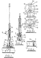
- the illustrated apparatus in accordance with the present invention is shown mounted to a water mains pipe 1 and comprises a stopping bag support device 2 mounted at the end of post 3a which is an extension of a stopping bag insertion tube 3 which is itself mounted within a conventional machine assembly 4 designed to a performance of various operations on a pressurised water mains pipe.
- the machine assembly 4 comprises a machine base 5 which may be secured to the pipe 1 by a chain or the like (not shown) and sealed with respect to the pipe by an annular sealing member 6.
- the machine base 5 houses a sliding plate valve 7 shown in Figure 1 in a closed position.
- the base 5 is of a universal nature providing a platform to which different machines can be mounted to perform operations on the pipe 1.
- a hole 8 has previously been drilled in the pipe using conventional drilling apparatus (not shown) mounted to the base 5 and then subsequently removed and replaced with the apparatus illustrated.
- the valve 7 is provided to seal the hole 8 in the pipe 1 as the drilling machine etc is removed and replaced.
- the bag insertion assembly comprises a conventional outer housing 9 which is sealed with respect to the base 5 by an annular sealing member 10.
- the housing 9 supports the bag insertion tube 3/3a which is sealed with respect to the housing 9 by annular sealing members 11 and 12.
- the bag insertion tube 3 in turn supports a bag insertion tool 13a which has a bag (at this stage not inflated) 13 fixed to its lower end (indicated only schematically in the figures).
- the insertion tube 3/3a further carries the support device 2 and an associated actuating rod 14.
- the support device 2 comprises four slats, numbered 15, 16, 17 and 18 respectively, each pivotably secured to the bag insertion tube extension 3a about a common pivot 19 located at the lower end of the post 3a.
- the slats 15, 16, 17 and 18 are generally rectangular of the same width as the tube extension 3a, but have arcuately profiled end edges to conform with the curvature of the bore of the pipe (see Figures 2 and 3).
- the actuating rod 14 has at its lower end an actuating pin which travels in curved slots 20-23 provided in each of the slats 15-18 respectively. It will be seen that the two slats 15 and 18 are mirror images of one another, as are the respective slats 20 and 23. Similarly, the slots 16 and 17, and respective slots 21 and 22 are mirror images of one another.
- the assembly is initially mounted to the machine base 5 (subsequent to drilling of the hole 8) as illustrated in Figure 1.
- the valve 7 is then opened and the bag insertion tube 3/3a carrying the support device 2 is lowered through the hole 8 and into the pipe 1 until it contacts the bottom of the pipe.
- the slats will be in a closed position in which they are aligned with the extension 3a of the insertion tube 3 as illustrated in Figure 3a.
- the actuation rod 14 is then pushed downwards relative to the tube 3/3a thereby driving the actuating pin vertically within the slots 20 to 23.
- the curvature of the slots 20-23 is designed so that as the pin moves vertically (travelling within the slots), the slats 15-16 are caused to rotate about the pivot 19 and thereby fan out into an open configuration as illustrated in Figures 2 and 3b.
- the ends of each slat remote from the pivot 19 bear against the internal wall of the pipe 1 so that the slats 15-18, together with the post 3a of the insertion tube 3, form a blockage across the bore of the pipe.
- the opening movement of the slats is to some extent aided by the profile of their lower edges and the pressure exerted on those lower edges as the device 2 bears against the bottom of the pipe 1. That is, the downward force exerted by the tube 3/3a exerts a turning moment about the point of contact between the slats 15-18 and the pipe wall tending to bias the slats towards the open position.
- the bag insertion tool 13 can then be lowered into the position illustrated in Figure 2 to insert the bag 13a through the hole 7 (the bag 13 is not illustrated in Figure 2 to avoid obscuring details of the device 2). It will be appreciated that there is no need to make any changes to the machinery mounted to the base 5 to insert the bag 13.
- the bag can be inflated using conventional means (not shown). Once inflated the bag forms a sealed blockage within the bore of the pipe 1 and is supported by the support device 2, as illustrated in Figure 4.
- Removal of the bag may be performed in a conventional way and removal of the support device 2 is simply the reverse of the procedure described above. Once the apparatus has been removed the single and relatively small hole 8 can be readily sealed in any conventional way.
- the structure of the support device 2 of the present invention has a number of advantages over the iris structure discussed in the introduction to this specification.
- the device, and in particular the actuating mechanism is less bulky than that of the prior art allowing it to be inserted through a relatively small hole on the end of a modified bag insertion tube. Pivoting the slats about one end, rather than about the middle, ensures that the ends of the slats which are brought to bear against the pipe wall approached the pipe wall substantially normally, i.e. the slats do not have to sweep across the inside of the pipe wall and are therefore not as vulnerable to the presence of obstructions on the pipe wall as the prior art device.
- the device can be partially opened without damage and still provide a safe and effective support.
- Location of the pivot and actuating mechanism at the end of the slats remote from the hole in the pipe ensures that the hole is substantially unobstructed when the support device is deployed so that the bag can be inserted through the same hole. This both avoids the need to drill a separate hole for bag insertion, and also enables the size of the single hole to be minimised.
- actuating rod may be spring assisted in either direction and may be lockable in either of the open and closed positions. Movement of the actuating rod (and also the tube and post 3/3a) may be manual or may be power assisted, e.g. by a hydraulic system. Suitable hydraulic systems using the pressurised fluid from the pipe are well known.
- the slats could be interconnected by a series of suitably pivoted and configured interlinking arms.
- the number and design of the slats may vary considerably.
- the bag insertion tube 3a may not be inserted centrally within the pipe but may, for instance, be offset to one side in which case the length and shape of the slats will need to be designed appropriately.
- webbing such as a rubber or similar flexible sheet
- webbing may be included to interconnected the slats to close the gaps therebetween (when in the open position) thereby further obstructing flow through the pipe.
- a modified device may be sufficient to obviate the need for a stopping bag or similar device in some applications. It will be appreciated that the idea of providing the webbing could be applied to other structures, including the known iris structure discussed in the introduction to this specification.
- spike or similar means may be provided at the lower end of the post 3a to engage the pipe wall both to help prevent the device from being pushed along the pipe and to prevent the post 3a or slats from bending which might otherwise inhibit opening or closing of the slats.
Landscapes
- Engineering & Computer Science (AREA)
- General Engineering & Computer Science (AREA)
- Mechanical Engineering (AREA)
- Pipe Accessories (AREA)
- Heat Treatment Of Articles (AREA)
- Quick-Acting Or Multi-Walled Pipe Joints (AREA)
Abstract
Description
Claims (19)
- A method of blocking the bore of a pipe through which fluid flows, comprising:characterised by inserting an inflatable bladder (13a) through said aperture (8) in the bore of the pipe (1) following deployment of said apparatus (2), and subsequently inflating said bladder (13a) to form a blockage in the pipe (1) adjacent to, and supported by, said apparatus (2).drilling an aperture (1) in the wall of the pipe (1) and inserting therethrough apparatus (2) comprising a plurality of elongate shutter members (15-18) pivotably mounted to an elongate support member (3a), actuating means (14) for pivoting said shutter members (15,16,17,18) from an insertion configuration in which they are substantially aligned with said support member (3a) and a deployed configuration in which they are fanned out across the bore of the pipe (1) to at least partially block said bore, wherein each shutter member (15,16,17,18) is pivoted about a point (19) located towards one end thereof and towards the insertion end of the support member (3a) so as in use to lie between the axis of the bore of the pipe (1) and the wall of the pipe opposite the location of said aperture (8);deploying said apparatus (2) in the bore of the pipe (1); and
- A method according to claim 1, wherein said aperture (8) is substantially circular and no greater than approximately ¼ of the diameter of the bore of the pipe (1).
- Apparatus for blocking the bore of a pipe through which fluid flows, the apparatus comprising a plurality of elongate shutter members (15,16,17,18) pivotably mounted to an elongate support member (3a) for insertion through a pre-drilled aperture (8) in the pipe wall, actuating means (14) for pivoting said shutter members (15,16,17,18) from an insertion configuration in which they are substantially aligned with said support member (3a) and a deployed configuration in which they are fanned out across the bore of the pipe (1) to at least partially block said bore, wherein each shutter member (15,16,17,18) is pivoted about a point (19) located towards one end thereof and towards the insertion end of the support member (3a) so as in use to lie between the axis of the bore of the pipe (1) and the wall of the pipe (1) opposite the location of said aperture (8), characterised by an inflatable bladder (13a) and in that said support member (3a) is an extension of a tubular member (3) adapted for insertion of said inflatable bladder (13a) through said aperture (8).
- Apparatus according to claim 3, wherein the or each pivot point (9) is located adjacent said end of the respective shutter member (15,16,17,18) and adjacent the insertion end of the support member (3a).
- Apparatus according to claim 3 or claim 4, wherein the insertion end of the support member (3a) in use bears against the wall of the pipe (1) opposite said aperture (8).
- Apparatus according to any one of claims 3 to 5, wherein an end of at least one of said shutter members towards (15,16,17,18) which the pivot (9) is located is adapted to bear against the wall of the pipe (1) opposite the aperture (8).
- Apparatus according to claims 6, wherein said end of said at least one shutter member (15,16,17,18) is profiled such that pressure exerted by the member (15,16,17,18) on the pipe wall produces a turning moment which tends to bias the shutter member (15,16,17,18) towards its deployed configuration.
- Apparatus according to any one of claims 3 to 7, wherein all of the shutter members (15,16,17,18) are pivoted about a common pivot (9).
- Apparatus according to any one of claims 3 to 8, wherein the assembly of shutter members (15,16,17,18) comprises shutter members of differing lengths, the length of the shutter members being such that with the shutter assembly fully deployed ends of each shutter member (15,16,17,18) remote from said pivot (9) will bear against the wall of the pipe (1).
- Apparatus according to any one of claims 3 to 9, wherein the shutter members (15,16,17,18) are shaped, and the pivot point (9) located, such that as the shutter members (15,16,17,18) fan out into the deployed configuration the end of each shutter member (15,16,17,18) remote from said pivot (9) approaches the pipe (1) wall substantially normally.
- Apparatus according to any one of claims 3 to 10, wherein a flexible web extends between each of the shutter members (15,16,17,18) to prevent a gap forming between adjacent shutting members (15,16,17,18) when in the deployed configuration.
- Apparatus according to claim 11, wherein said web is formed from a flexible material which stretches as said shutter members (15-18) move from insertion configuration to the deployed configuration.
- Apparatus according to claim 11 or 12, wherein said web is made from a flexible material which unfolds and folds as the shutter members (15-18) are moved between the insertion and deployed configurations.
- Apparatus according to any one of claims 3 to 13, wherein the actuating means (14) acts on the shutter members (15,16,17,18) in a region adjacent said pivot point (9) and towards said insertion end of the support member (3a).
- Apparatus according to claim 14, wherein the actuating means comprises an elongate actuating member (14) which in use extends through said aperture (8) in the pipe (1) allowing remote operation of the shutter assembly (15,16,17,18).
- Apparatus according to claim 15, wherein the actuating means comprises a mechanism for converting transitional and/or rotational movement of the actuating member (14) into movement of the shutter members (15,16,17,18), said mechanism being located adjacent said pivot point (9) towards said insertion end of the support member (3a).
- Apparatus according to claim 16, wherein said mechanism comprises an actuating pin carried by the actuating member (14) which travels in slots (20-23) defined in each of said shutter members (15-18), the slots (20-23) being profiled such that vertical movement of the actuating member (14) and actuating pin exerts a turning moment on each of the shutter members (15-18) causing the shutter members (15-18) to move from said insertion to said deployed configuration and vice versa.
- Apparatus according to any one of claims 3 to 16, wherein the actuating means comprises an elongate actuating member (14) which extends through said tubular member (3).
- Apparatus according to any one of claims 3 to 18, comprising four of said elongate shutter members (15-18).
Applications Claiming Priority (3)
| Application Number | Priority Date | Filing Date | Title |
|---|---|---|---|
| GBGB9923263.9A GB9923263D0 (en) | 1999-10-02 | 1999-10-02 | Method and apparatus for blocking pipes |
| GB9923263 | 1999-10-02 | ||
| PCT/GB2000/003771 WO2001025676A1 (en) | 1999-10-02 | 2000-10-02 | Method and apparatus for blocking pipes |
Publications (2)
| Publication Number | Publication Date |
|---|---|
| EP1218661A1 EP1218661A1 (en) | 2002-07-03 |
| EP1218661B1 true EP1218661B1 (en) | 2005-03-02 |
Family
ID=10861965
Family Applications (1)
| Application Number | Title | Priority Date | Filing Date |
|---|---|---|---|
| EP00964470A Expired - Lifetime EP1218661B1 (en) | 1999-10-02 | 2000-10-02 | Method and apparatus for blocking pipes |
Country Status (7)
| Country | Link |
|---|---|
| US (1) | US6588455B1 (en) |
| EP (1) | EP1218661B1 (en) |
| AT (1) | ATE290185T1 (en) |
| AU (1) | AU7540400A (en) |
| DE (1) | DE60018439T2 (en) |
| GB (1) | GB9923263D0 (en) |
| WO (1) | WO2001025676A1 (en) |
Families Citing this family (9)
| Publication number | Priority date | Publication date | Assignee | Title |
|---|---|---|---|---|
| US7000641B2 (en) | 2000-11-02 | 2006-02-21 | Crane Limited | Inflatable stopping bags |
| US7270139B2 (en) * | 2005-04-25 | 2007-09-18 | Tdw Delaware, Inc. | Cam-assisted, wedge actuated, metal-to-metal seal, block and bleed plugging tool |
| US8132783B2 (en) * | 2007-09-12 | 2012-03-13 | Lumec Control Products, Inc | Dynamic orifice valve apparatus and method |
| ITRM20080189A1 (en) * | 2008-04-10 | 2009-10-11 | Armando Carravetta | DEVICE FOR THE ADJUSTMENT AND MEASUREMENT OF FLUID DISTRIBUTION NETWORKS |
| US8104517B2 (en) | 2009-06-03 | 2012-01-31 | Mueller International, Inc. | Resilient plug apparatus and method of use |
| EP2788648B1 (en) * | 2011-12-06 | 2017-05-10 | Saudi Arabian Oil Company | Block valve isolation inflatable tool |
| US9447889B2 (en) * | 2011-12-06 | 2016-09-20 | Saudi Arabian Oil Company | Blocked valve isolation tool |
| US9175786B2 (en) | 2013-08-30 | 2015-11-03 | Lumec Control Products, Inc. | Valve apparatus |
| CN115464742A (en) * | 2022-08-25 | 2022-12-13 | 江西吉中竹业有限公司 | Bamboo-based fiber textile yarn drum production device and production process thereof |
Family Cites Families (10)
| Publication number | Priority date | Publication date | Assignee | Title |
|---|---|---|---|---|
| US2482696A (en) * | 1944-11-29 | 1949-09-20 | Mueller Co | Pipe-line stopper |
| US2476907A (en) * | 1945-07-07 | 1949-07-19 | William E Preston | Pipe-line stopper |
| US3115163A (en) * | 1960-09-12 | 1963-12-24 | Kenneth S Van Epps | Means for stopping the flow of fluid in a conduit |
| GB1311017A (en) | 1970-12-16 | 1973-03-21 | Gas Council | Method and apparatus for blocking pressure pipes |
| US4458721A (en) * | 1979-02-28 | 1984-07-10 | Brooklyn Union Gas Company | Pipeline flow restrictor |
| EP0027027A1 (en) * | 1979-10-02 | 1981-04-15 | Gerald John Evans | Flexible gate valve |
| GB8315198D0 (en) * | 1983-06-02 | 1983-07-06 | Alh Syst Ltd | Sealing pipes |
| GB2204660B (en) * | 1987-04-11 | 1991-04-17 | Pentec Engineering Services Li | Valve arrangement |
| US5778919A (en) * | 1993-12-30 | 1998-07-14 | Custom Service Laboratories Of N.J., Inc. | Pipeline flow stopper with dual shafts |
| SE502633C2 (en) * | 1994-04-08 | 1995-11-27 | Tigerholm Ab | Method and apparatus for blocking fluid in a pressurized conduit |
-
1999
- 1999-10-02 GB GBGB9923263.9A patent/GB9923263D0/en not_active Ceased
-
2000
- 2000-10-02 US US10/089,655 patent/US6588455B1/en not_active Expired - Fee Related
- 2000-10-02 AT AT00964470T patent/ATE290185T1/en not_active IP Right Cessation
- 2000-10-02 EP EP00964470A patent/EP1218661B1/en not_active Expired - Lifetime
- 2000-10-02 DE DE60018439T patent/DE60018439T2/en not_active Expired - Lifetime
- 2000-10-02 WO PCT/GB2000/003771 patent/WO2001025676A1/en not_active Ceased
- 2000-10-02 AU AU75404/00A patent/AU7540400A/en not_active Abandoned
Also Published As
| Publication number | Publication date |
|---|---|
| WO2001025676A1 (en) | 2001-04-12 |
| AU7540400A (en) | 2001-05-10 |
| US6588455B1 (en) | 2003-07-08 |
| ATE290185T1 (en) | 2005-03-15 |
| EP1218661A1 (en) | 2002-07-03 |
| DE60018439D1 (en) | 2005-04-07 |
| GB9923263D0 (en) | 1999-12-08 |
| DE60018439T2 (en) | 2006-02-16 |
Similar Documents
| Publication | Publication Date | Title |
|---|---|---|
| US6588455B1 (en) | Method and apparatus for blocking pipes | |
| AU2003286260B2 (en) | Fluid collecting device | |
| US4458721A (en) | Pipeline flow restrictor | |
| JP5507571B2 (en) | Improved double block and fluid discharge plug | |
| ES2691681T3 (en) | Insulation tool | |
| RU2097645C1 (en) | Method and device for blocking liquid in pipe | |
| US2812778A (en) | Pipe line plugger | |
| MX2013006685A (en) | Plugging device. | |
| US3431946A (en) | Inflatable pipe plug | |
| CA2783410A1 (en) | Resilient plug apparatus and method of use | |
| GB2297106A (en) | Shifting tool | |
| US3025885A (en) | Pipe line plugger | |
| US3717202A (en) | Remote well plugging apparatus | |
| US6745791B2 (en) | Service tools for pipelines containing conduit or cable | |
| GB2064703A (en) | Unblocking and repairing conduits | |
| CN216143379U (en) | Non-excavation prosthetic devices that double-walled bellows part is incomplete sinks | |
| EP1356187B1 (en) | Methods and mechanisms to set a hollow device into and to retrieve said hollow device from a flow pipe | |
| AU2001261938A1 (en) | Methods and mechanism to set a hollow device into and to retrieve said hollow device from a flow pipe | |
| HU216763B (en) | Device for blocking a tract by an inflatable hose | |
| JPH07190282A (en) | Device for temporarily closing duct in which fluid is carried | |
| NL8801329A (en) | REMOVABLE HINGE, PARTICULARLY FOR ATTACHING TO THE BOTTOM OF EQUIPMENT AT UNDERWATER INSTALLATIONS. | |
| KR20010022513A (en) | Safety valve | |
| EP0060715B1 (en) | Pipe sealing apparatus and jack | |
| GB2420362A (en) | Fluid collecting device | |
| RU2285189C2 (en) | Device for cutting off operating pipeline |
Legal Events
| Date | Code | Title | Description |
|---|---|---|---|
| PUAI | Public reference made under article 153(3) epc to a published international application that has entered the european phase |
Free format text: ORIGINAL CODE: 0009012 |
|
| 17P | Request for examination filed |
Effective date: 20020326 |
|
| AK | Designated contracting states |
Kind code of ref document: A1 Designated state(s): AT BE CH CY DE DK ES FI FR GB GR IE IT LI LU MC NL PT SE |
|
| AX | Request for extension of the european patent |
Free format text: AL;LT;LV;MK;RO;SI |
|
| 17Q | First examination report despatched |
Effective date: 20031013 |
|
| GRAP | Despatch of communication of intention to grant a patent |
Free format text: ORIGINAL CODE: EPIDOSNIGR1 |
|
| GRAS | Grant fee paid |
Free format text: ORIGINAL CODE: EPIDOSNIGR3 |
|
| GRAA | (expected) grant |
Free format text: ORIGINAL CODE: 0009210 |
|
| AK | Designated contracting states |
Kind code of ref document: B1 Designated state(s): AT BE CH CY DE DK ES FI FR GB GR IE IT LI LU MC NL PT SE |
|
| PG25 | Lapsed in a contracting state [announced via postgrant information from national office to epo] |
Ref country code: AT Free format text: LAPSE BECAUSE OF FAILURE TO SUBMIT A TRANSLATION OF THE DESCRIPTION OR TO PAY THE FEE WITHIN THE PRESCRIBED TIME-LIMIT Effective date: 20050302 Ref country code: IT Free format text: LAPSE BECAUSE OF FAILURE TO SUBMIT A TRANSLATION OF THE DESCRIPTION OR TO PAY THE FEE WITHIN THE PRESCRIBED TIME-LIMIT;WARNING: LAPSES OF ITALIAN PATENTS WITH EFFECTIVE DATE BEFORE 2007 MAY HAVE OCCURRED AT ANY TIME BEFORE 2007. THE CORRECT EFFECTIVE DATE MAY BE DIFFERENT FROM THE ONE RECORDED. Effective date: 20050302 Ref country code: CH Free format text: LAPSE BECAUSE OF FAILURE TO SUBMIT A TRANSLATION OF THE DESCRIPTION OR TO PAY THE FEE WITHIN THE PRESCRIBED TIME-LIMIT Effective date: 20050302 Ref country code: FR Free format text: LAPSE BECAUSE OF NON-PAYMENT OF DUE FEES Effective date: 20050302 Ref country code: LI Free format text: LAPSE BECAUSE OF FAILURE TO SUBMIT A TRANSLATION OF THE DESCRIPTION OR TO PAY THE FEE WITHIN THE PRESCRIBED TIME-LIMIT Effective date: 20050302 Ref country code: FI Free format text: LAPSE BECAUSE OF FAILURE TO SUBMIT A TRANSLATION OF THE DESCRIPTION OR TO PAY THE FEE WITHIN THE PRESCRIBED TIME-LIMIT Effective date: 20050302 |
|
| REG | Reference to a national code |
Ref country code: GB Ref legal event code: FG4D |
|
| REG | Reference to a national code |
Ref country code: CH Ref legal event code: EP |
|
| REG | Reference to a national code |
Ref country code: IE Ref legal event code: FG4D |
|
| REF | Corresponds to: |
Ref document number: 60018439 Country of ref document: DE Date of ref document: 20050407 Kind code of ref document: P |
|
| PG25 | Lapsed in a contracting state [announced via postgrant information from national office to epo] |
Ref country code: DK Free format text: LAPSE BECAUSE OF FAILURE TO SUBMIT A TRANSLATION OF THE DESCRIPTION OR TO PAY THE FEE WITHIN THE PRESCRIBED TIME-LIMIT Effective date: 20050602 Ref country code: GR Free format text: LAPSE BECAUSE OF FAILURE TO SUBMIT A TRANSLATION OF THE DESCRIPTION OR TO PAY THE FEE WITHIN THE PRESCRIBED TIME-LIMIT Effective date: 20050602 |
|
| PG25 | Lapsed in a contracting state [announced via postgrant information from national office to epo] |
Ref country code: ES Free format text: LAPSE BECAUSE OF FAILURE TO SUBMIT A TRANSLATION OF THE DESCRIPTION OR TO PAY THE FEE WITHIN THE PRESCRIBED TIME-LIMIT Effective date: 20050613 |
|
| PG25 | Lapsed in a contracting state [announced via postgrant information from national office to epo] |
Ref country code: PT Free format text: LAPSE BECAUSE OF FAILURE TO SUBMIT A TRANSLATION OF THE DESCRIPTION OR TO PAY THE FEE WITHIN THE PRESCRIBED TIME-LIMIT Effective date: 20050817 |
|
| REG | Reference to a national code |
Ref country code: CH Ref legal event code: PL |
|
| PG25 | Lapsed in a contracting state [announced via postgrant information from national office to epo] |
Ref country code: CY Free format text: LAPSE BECAUSE OF FAILURE TO SUBMIT A TRANSLATION OF THE DESCRIPTION OR TO PAY THE FEE WITHIN THE PRESCRIBED TIME-LIMIT Effective date: 20051002 |
|
| PG25 | Lapsed in a contracting state [announced via postgrant information from national office to epo] |
Ref country code: IE Free format text: LAPSE BECAUSE OF NON-PAYMENT OF DUE FEES Effective date: 20051003 |
|
| PG25 | Lapsed in a contracting state [announced via postgrant information from national office to epo] |
Ref country code: MC Free format text: LAPSE BECAUSE OF NON-PAYMENT OF DUE FEES Effective date: 20051031 Ref country code: LU Free format text: LAPSE BECAUSE OF NON-PAYMENT OF DUE FEES Effective date: 20051031 |
|
| REG | Reference to a national code |
Ref country code: GB Ref legal event code: 732E |
|
| PLBE | No opposition filed within time limit |
Free format text: ORIGINAL CODE: 0009261 |
|
| STAA | Information on the status of an ep patent application or granted ep patent |
Free format text: STATUS: NO OPPOSITION FILED WITHIN TIME LIMIT |
|
| RAP2 | Party data changed (patent owner data changed or rights of a patent transferred) |
Owner name: CRANE LIMITED |
|
| 26N | No opposition filed |
Effective date: 20051205 |
|
| NLT2 | Nl: modifications (of names), taken from the european patent patent bulletin |
Owner name: CRANE LIMITED Effective date: 20060118 |
|
| EN | Fr: translation not filed | ||
| NLS | Nl: assignments of ep-patents |
Owner name: CRANE LIMITED Effective date: 20060413 |
|
| REG | Reference to a national code |
Ref country code: IE Ref legal event code: MM4A |
|
| BECA | Be: change of holder's address |
Owner name: CRANE LTDNACTON ROAD, IPSWICH, SUFFOLK IP3 9QH Effective date: 20050302 |
|
| BECH | Be: change of holder |
Owner name: CRANE LTD Effective date: 20050302 |
|
| REG | Reference to a national code |
Ref country code: FR Ref legal event code: TP |
|
| PG25 | Lapsed in a contracting state [announced via postgrant information from national office to epo] |
Ref country code: SE Free format text: LAPSE BECAUSE OF FAILURE TO SUBMIT A TRANSLATION OF THE DESCRIPTION OR TO PAY THE FEE WITHIN THE PRESCRIBED TIME-LIMIT Effective date: 20050602 |
|
| PGFP | Annual fee paid to national office [announced via postgrant information from national office to epo] |
Ref country code: DE Payment date: 20100929 Year of fee payment: 11 |
|
| PGFP | Annual fee paid to national office [announced via postgrant information from national office to epo] |
Ref country code: NL Payment date: 20111021 Year of fee payment: 12 Ref country code: BE Payment date: 20111012 Year of fee payment: 12 |
|
| BERE | Be: lapsed |
Owner name: CRANE LTD Effective date: 20121031 |
|
| REG | Reference to a national code |
Ref country code: NL Ref legal event code: V1 Effective date: 20130501 |
|
| PG25 | Lapsed in a contracting state [announced via postgrant information from national office to epo] |
Ref country code: DE Free format text: LAPSE BECAUSE OF NON-PAYMENT OF DUE FEES Effective date: 20130501 Ref country code: BE Free format text: LAPSE BECAUSE OF NON-PAYMENT OF DUE FEES Effective date: 20121031 |
|
| REG | Reference to a national code |
Ref country code: DE Ref legal event code: R119 Ref document number: 60018439 Country of ref document: DE Effective date: 20130501 |
|
| PG25 | Lapsed in a contracting state [announced via postgrant information from national office to epo] |
Ref country code: NL Free format text: LAPSE BECAUSE OF NON-PAYMENT OF DUE FEES Effective date: 20130501 |
|
| PGFP | Annual fee paid to national office [announced via postgrant information from national office to epo] |
Ref country code: GB Payment date: 20191003 Year of fee payment: 20 |
|
| REG | Reference to a national code |
Ref country code: GB Ref legal event code: PE20 Expiry date: 20201001 |
|
| PG25 | Lapsed in a contracting state [announced via postgrant information from national office to epo] |
Ref country code: GB Free format text: LAPSE BECAUSE OF EXPIRATION OF PROTECTION Effective date: 20201001 |