EP1217728A2 - Cable modem tuner - Google Patents
Cable modem tuner Download PDFInfo
- Publication number
- EP1217728A2 EP1217728A2 EP01124901A EP01124901A EP1217728A2 EP 1217728 A2 EP1217728 A2 EP 1217728A2 EP 01124901 A EP01124901 A EP 01124901A EP 01124901 A EP01124901 A EP 01124901A EP 1217728 A2 EP1217728 A2 EP 1217728A2
- Authority
- EP
- European Patent Office
- Prior art keywords
- circuit
- output
- amplifying circuit
- signal
- cable modem
- Prior art date
- Legal status (The legal status is an assumption and is not a legal conclusion. Google has not performed a legal analysis and makes no representation as to the accuracy of the status listed.)
- Withdrawn
Links
Images



Classifications
-
- H—ELECTRICITY
- H04—ELECTRIC COMMUNICATION TECHNIQUE
- H04L—TRANSMISSION OF DIGITAL INFORMATION, e.g. TELEGRAPHIC COMMUNICATION
- H04L27/00—Modulated-carrier systems
- H04L27/32—Carrier systems characterised by combinations of two or more of the types covered by groups H04L27/02, H04L27/10, H04L27/18 or H04L27/26
- H04L27/34—Amplitude- and phase-modulated carrier systems, e.g. quadrature-amplitude modulated carrier systems
- H04L27/38—Demodulator circuits; Receiver circuits
Definitions
- the present invention relates to a cable modem tuner. More specifically, the present invention relates to a cable modem tuner suitable for outputting an intermediate frequency signal to a QAM (Quadrature Amplitude Modulation) demodulating circuit.
- QAM Quadrature Amplitude Modulation
- HFC Hybrid Fiber/Coax
- a coaxial cable is kept as a subscriber's drop wire and the main network is implemented by optical fibers.
- This system attempts to provide broad-band data communication service of several Mbits/sec at home. Utilizing this system, it is possible to realize high speed data line having the transmission rate of 30 Mbits/sec with the bandwidth of 6MHz using 64 QAM (Quadrature Amplitude Modulation).
- the cable modem is used in this system, and realizes high speed data communication of 4 Mbits/sec to 27 Mbits/sec, utilizing an unused channel of CATV.
- the cable modem tuner is used for a cable modem in such a CATV system, and after the received CATV signal is subjected to frequency conversion, it serves to take out the signal as an intermediate frequency signal.
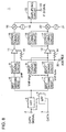
- Fig. 8 is a block diagram representing a configuration of a conventional cable modem tuner 1.
- an up signal transmitted to a station has the frequency of 5MHz to 42MHz
- a down signal transmitted from the station to the cable modem tuner has the frequency of 54MHz to 860MHz, and transmitted to a cable network through an input terminal 2 of the tuner.
- the up signal transmitted from the cable modem is received by a data receiver of the CATV station (system operator), and enters a computer of a center.
- the cable modem tuner 1 includes a CATV signal input terminal 2 receiving the CATV signal as an input, a data terminal 3 receiving a data signal from a QPSK transmitter as an input, and an upstream circuit 4 provided between data terminal 3 and CATV signal input terminal 2.
- a data signal subjected to quadrature phase shift keying (QPSK) from a QPSK transmitter, for example, is input to data terminal 3 as the up signal.
- the data signal is transmitted through upstream circuit 4 to the CATV station.
- QPSK quadrature phase shift keying
- the down signal input through input terminal 2 is divided into a UHF band receiving the frequency of 470 to 860MHz, a VHF-High band receiving the frequency of 170 to 470MHz and a VHF-Low band receiving the frequency of 54 to 170MHz, and processed by receiving circuits provided for respective bands.
- Band ranges are not limited to those specified above.
- the cable modem tuner 1 further includes a high pass filter (HPF) 5 having an attenuation range of 5 to 46MHz and a pass band of not lower than 54MHz, and input switching circuits 6 and 7 for allocating the signals passed through the high pass filter 5 to circuits corresponding to respective bands.
- HPF high pass filter
- the down signal is passed through high pass filter 5, the band is switched by the input switching circuits 6 and 7, and supplied to the circuitry corresponding to any of the aforementioned bands.
- Cable modem tuner 1 further includes high frequency amplification input tuning circuits 8, 9 and 10 provided corresponding to respective bands; high frequency amplification circuits 11 and 12 provided corresponding to the UHF band and VHF band, respectively; high frequency amplification output tuning circuits 15, 16 and 17 provided corresponding to respective bands; a mixer circuit 18 and a local oscillation circuit 19 provided corresponding to the UHF band; a mixer circuit 20 and a local oscillation circuit 21 provided corresponding to the VHF band; and an intermediate frequency amplifying circuit 22 for amplifying, in the intermediate frequency band, outputs from mixer circuits 18 and 20.
- the high frequency amplification input tuning circuits, the high frequency amplification circuits, the high frequency amplification output tuning circuits, the mixer circuits and the local oscillation circuits provided corresponding to respective bands are adapted such that dependent on the received channel, circuits corresponding to the received band are made operative, while the circuits corresponding to other bands are made inoperative.
- the high frequency amplification input tuning circuit 8 the high frequency amplification circuit 11, high frequency amplification output tuning circuit 15, mixer circuit 18 and local oscillation circuit 19 for the UHF band are set to the operative state, while high frequency amplification input tuning circuits 9 and 10, high frequency amplification circuit 12, high frequency amplification output tuning circuits 16 and 17, mixer circuit 20 and local oscillation circuit 21 for the VHF-High and VHF-Low bands are set to inoperative state, and stop their operation.
- the CATV signal input to the input terminal 2 is passed through high pass filter 5, and enters input switching circuits 6 and 7, where band switching takes place.
- the output therefrom is fed to high frequency amplification input tuning circuit 8, 9 or 10, where channel selection takes place.
- the signal is input to AGC terminal 24, amplified to a prescribed level by high frequency amplification circuit 11 or 12 based on the AGC voltage applied to resistance 13 or 14, supplied to high frequency output tuning circuit 15, 16 or 17, where the received signal is extracted.
- the selected received signal is subjected to frequency conversion by mixer circuit 18, 20 and local oscillation circuit 19, 21 to an intermediate frequency (IF), and amplified by intermediate frequency amplification circuit 22.
- the intermediate frequency signal amplified by intermediate frequency amplifying circuit 22 is output from output terminal 23.
- a received CATV signal is selected in accordance with the reception channel, and the signal after channel selection is subjected to frequency conversion and output as an IF signal from output terminal 23.
- Handling of a QAM signal, which is a digital signal, and transmitting the IF signal output from output terminal 23 to a QAM demodulating circuit, not shown, for QAM demodulation by using such a cable modem tuner 1 has the following various problems.
- a balanced type input circuit comes to be used in the QAM demodulating ICs. This means that the tuner must provide balanced IF outputs. Conventionally, however, it provides unbalanced outputs.
- an input signal level of about 0.5Vp-p is necessary for the QAM demodulating IC.
- the IF output of a conventional tuner does not have such a level.
- the input level of the QAM demodulating IC must be constant for reception signals.
- RF-AGC only, and variation of the reception signal level at the tuner input end cannot be controlled satisfactorily.
- an object of the present invention is to provide a cable modem tuner capable of outputting balanced intermediate frequency signals of high and constant level, to be applied to the QAM demodulating circuit.
- the present invention provides a cable modem tuner including a tuner portion taking and amplifying a signal corresponding to a reception channel from input signals and outputting an intermediate frequency signal, a surface acoustic wave filter connected to an output of the tuner portion, a gain control and intermediate frequency amplifying circuit connected to an output of the surface acoustic wave filter, a lowpass filter connected to an output of the gain control and intermediate frequency amplifying circuit, and an output circuit connected to an output of the lowpass filter.
- the IF signal to be applied to the QAM demodulating circuit can be secured to a constant level, and an IF signal can be provided even to a balanced type QAM demodulating circuit.
- the output circuit includes an unbalance/balance converting circuit converting unbalanced signals as outputs of the lowpass filter to balanced signals.
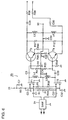
- resistances R35 and R36 are connected, and between the emitters a resistances R40 is connected. Further, between the collector of transistor T3 and power supply terminal 32, a bias resistance R37 and a coil L3 are connected, and between the collector of transistor T4 and power supply terminal 32, a bias resistance R12 and a coil L4 are connected. From the collectors of transistors T3 and T4, one of the IF balanced signals is output through DC preventing capacitor C35 and output buffer resistance R38, and the other one of the IF balanced signals is output through DC preventing capacitor C36 and output buffer resistance R39.
Landscapes
- Engineering & Computer Science (AREA)
- Computer Networks & Wireless Communication (AREA)
- Signal Processing (AREA)
- Circuits Of Receivers In General (AREA)
- Superheterodyne Receivers (AREA)
- Digital Transmission Methods That Use Modulated Carrier Waves (AREA)
- Two-Way Televisions, Distribution Of Moving Picture Or The Like (AREA)
Abstract
Description
Claims (6)
- A cable modem tuner including a tuner portion (1) taking and amplifying a signal corresponding to a reception channel from input signals and converting to an intermediate frequency signal, comprising
a surface acoustic wave filter (24) connected to an output of said tuner portion;
a gain control and intermediate frequency amplifying circuit (25) connected to an output of said surface acoustic wave filter;
a lowpass filter (27) connected to an output of said gain control and intermediate frequency amplifying circuit; and
an output circuit (28, 35, T1, T3, T4, T5) connected to an output of said lowpass filter. - The cable modem tuner according to claim 1, wherein
said output circuit includes an unbalance/balance converting circuit (28, 35) converting unbalanced signals of an output of said lowpass filter to balanced signals. - The cable modem tuner according to claim 1, wherein
said output circuit includes a differential amplifying circuit (T3, T4) providing an output of said lowpass filter as balanced signals. - The cable modem tuner according to claim 1, wherein
said gain control and intermediate frequency amplifying circuit includes a dual gate type MOSFET amplifying circuit (T1) receiving an output of said surface acoustic wave filter. - The cable modem tuner according to claim 1, wherein
said gain control and intermediate frequency amplifying circuit includes a balanced type dual gate MOSFET amplifying circuit (T1, T5) receiving an output of said surface acoustic wave filter. - The cable modem tuner according to claim 5, wherein
said gain control and intermediate frequency amplifying circuit includes a differential amplifying circuit (T3, T4) receiving an output of said balanced type dual gate MOSFET amplifying circuit.
Applications Claiming Priority (2)
| Application Number | Priority Date | Filing Date | Title |
|---|---|---|---|
| JP2000364554 | 2000-11-30 | ||
| JP2000364554A JP4064620B2 (en) | 2000-11-30 | 2000-11-30 | Tuner for cable modem |
Publications (2)
| Publication Number | Publication Date |
|---|---|
| EP1217728A2 true EP1217728A2 (en) | 2002-06-26 |
| EP1217728A3 EP1217728A3 (en) | 2004-04-28 |
Family
ID=18835477
Family Applications (1)
| Application Number | Title | Priority Date | Filing Date |
|---|---|---|---|
| EP01124901A Withdrawn EP1217728A3 (en) | 2000-11-30 | 2001-10-18 | Cable modem tuner |
Country Status (3)
| Country | Link |
|---|---|
| US (1) | US7289566B2 (en) |
| EP (1) | EP1217728A3 (en) |
| JP (1) | JP4064620B2 (en) |
Families Citing this family (5)
| Publication number | Priority date | Publication date | Assignee | Title |
|---|---|---|---|---|
| CN1190964C (en) * | 2000-02-14 | 2005-02-23 | 夏普公司 | Tuner of cable modem |
| JP2009027688A (en) * | 2007-06-19 | 2009-02-05 | Alps Electric Co Ltd | Digital television broadcast/receiving diversity apparatus and vehicle-mounted terrestrial digital receiver |
| JP2009027463A (en) * | 2007-07-19 | 2009-02-05 | Sharp Corp | Terrestrial TV and CATV shared receiver |
| US20100061432A1 (en) * | 2008-09-11 | 2010-03-11 | Texas Instruments Incorporated | Reduced cost saw-less catv rf tuner circuit for use in a cable modem |
| JP6069115B2 (en) * | 2013-06-25 | 2017-02-01 | 日本電信電話株式会社 | Video generation device, video generation method, and program |
Family Cites Families (24)
| Publication number | Priority date | Publication date | Assignee | Title |
|---|---|---|---|---|
| US3852522A (en) * | 1973-05-21 | 1974-12-03 | Warwick Electronics Inc | Variable q if amplifier |
| JPS6448584A (en) * | 1987-08-18 | 1989-02-23 | Alps Electric Co Ltd | Catv converter |
| JPH0429277A (en) | 1990-05-25 | 1992-01-31 | Hitachi Koki Co Ltd | Electrophotographic printer |
| US5365279A (en) * | 1992-09-08 | 1994-11-15 | Samsung Electronics Co., Ltd. | Using D-C feedback with on-chip filtering to balance I-F drive to second detector in monolithic IC |
| JPH0779390A (en) | 1993-06-15 | 1995-03-20 | Matsushita Electric Ind Co Ltd | Receiver |
| US5479137A (en) * | 1993-12-14 | 1995-12-26 | Samsung Electronics Co., Ltd. | Controlled oscillator, as for synchyronous video detector |
| JPH08331474A (en) | 1995-05-30 | 1996-12-13 | Sanyo Electric Co Ltd | Multi-system dealing receiver |
| JPH0965236A (en) | 1995-08-24 | 1997-03-07 | Toshiba Corp | Digital broadcast receiver |
| US5608724A (en) * | 1995-09-27 | 1997-03-04 | Nippondenso Co., Ltd. | Dynamically reconfigurable frequency division multiplexer and modulator |
| JP3627783B2 (en) | 1996-12-26 | 2005-03-09 | シャープ株式会社 | Tuner for cable modem |
| JP3813688B2 (en) | 1997-04-18 | 2006-08-23 | 株式会社東芝 | Bidirectional CATV transmitter |
| GB2325804B (en) * | 1997-05-30 | 2001-01-03 | Daewoo Electronics Co Ltd | Method and apparatus for selectively receiving a satellite broadcast signal or a cable television signal |
| JP3753518B2 (en) * | 1997-10-24 | 2006-03-08 | シャープ株式会社 | Tuner for cable modem |
| JP3938232B2 (en) | 1997-11-28 | 2007-06-27 | シャープ株式会社 | Tuner for cable modem |
| US6160571A (en) * | 1998-05-04 | 2000-12-12 | Isg Broadband, Inc. | Compact cable tuner/transceiver |
| JP3604912B2 (en) | 1998-07-23 | 2004-12-22 | シャープ株式会社 | Tuner for cable modem |
| JP2000115263A (en) * | 1998-09-30 | 2000-04-21 | Matsushita Electric Ind Co Ltd | Digital broadcast demodulator |
| JP4248637B2 (en) | 1998-11-09 | 2009-04-02 | シャープ株式会社 | Tuner for cable modem |
| JP2001008179A (en) * | 1999-04-23 | 2001-01-12 | Sharp Corp | Tuner for CATV |
| US6714776B1 (en) * | 1999-09-28 | 2004-03-30 | Microtune (Texas), L.P. | System and method for an image rejecting single conversion tuner with phase error correction |
| US6396550B1 (en) * | 1999-11-05 | 2002-05-28 | Samsung Electronics Co., Ltd. | Method and device for precision tuning, and method and device for matching vestigial sideband signal in television |
| JP2001168647A (en) * | 1999-12-13 | 2001-06-22 | Hitachi Ltd | High frequency power amplifier module and wireless communication device |
| CN1190964C (en) * | 2000-02-14 | 2005-02-23 | 夏普公司 | Tuner of cable modem |
| US6437657B1 (en) * | 2000-09-25 | 2002-08-20 | National Semiconductor Corporation | Differential conversion circuit with a larger coupling capacitor than resonator capacitor |
-
2000
- 2000-11-30 JP JP2000364554A patent/JP4064620B2/en not_active Expired - Fee Related
-
2001
- 2001-10-18 EP EP01124901A patent/EP1217728A3/en not_active Withdrawn
- 2001-10-19 US US09/981,925 patent/US7289566B2/en not_active Expired - Fee Related
Also Published As
| Publication number | Publication date |
|---|---|
| EP1217728A3 (en) | 2004-04-28 |
| US7289566B2 (en) | 2007-10-30 |
| JP2002171500A (en) | 2002-06-14 |
| JP4064620B2 (en) | 2008-03-19 |
| US20020064238A1 (en) | 2002-05-30 |
Similar Documents
| Publication | Publication Date | Title |
|---|---|---|
| EP1128556B1 (en) | Cable modem tuner | |
| JP3627783B2 (en) | Tuner for cable modem | |
| EP1047192B1 (en) | CATV tuner | |
| US6124766A (en) | Frequency converter circuit for cable modem tuner | |
| EP1217728A2 (en) | Cable modem tuner | |
| JP3719926B2 (en) | Digital signal receiving tuner | |
| EP1250006B1 (en) | Cable modem tuner | |
| JP3564028B2 (en) | Tuner for cable modem | |
| US7447489B2 (en) | Digital tuner | |
| JP2000151272A (en) | Tuner for cable modem | |
| JP3360364B2 (en) | Intermediate frequency processing circuit of balanced output type tuner device | |
| JPH08289221A (en) | Digital / analog shared tuner | |
| JP2519672Y2 (en) | Distributor | |
| US6754480B1 (en) | Baseband analog circuit with improved noise characteristics | |
| JP2001268530A (en) | Tuner for CATV | |
| JP2000175164A (en) | Network interface module | |
| US20030218697A1 (en) | Broadband television tuner front end | |
| JPH10271027A (en) | Satellite receiver | |
| JP2000287099A (en) | Analog fpu device | |
| KR20110047681A (en) | RF signal processing circuit |
Legal Events
| Date | Code | Title | Description |
|---|---|---|---|
| PUAI | Public reference made under article 153(3) epc to a published international application that has entered the european phase |
Free format text: ORIGINAL CODE: 0009012 |
|
| AK | Designated contracting states |
Kind code of ref document: A2 Designated state(s): AT BE CH CY DE DK ES FI FR GB GR IE IT LI LU MC NL PT SE TR |
|
| AX | Request for extension of the european patent |
Free format text: AL;LT;LV;MK;RO;SI |
|
| PUAL | Search report despatched |
Free format text: ORIGINAL CODE: 0009013 |
|
| AK | Designated contracting states |
Kind code of ref document: A3 Designated state(s): AT BE CH CY DE DK ES FI FR GB GR IE IT LI LU MC NL PT SE TR |
|
| AX | Request for extension of the european patent |
Extension state: AL LT LV MK RO SI |
|
| RIC1 | Information provided on ipc code assigned before grant |
Ipc: 7H 03J 5/24 B Ipc: 7H 03G 1/00 B Ipc: 7H 03G 3/30 A |
|
| 17P | Request for examination filed |
Effective date: 20040901 |
|
| 17Q | First examination report despatched |
Effective date: 20041117 |
|
| AKX | Designation fees paid |
Designated state(s): DE FR |
|
| STAA | Information on the status of an ep patent application or granted ep patent |
Free format text: STATUS: THE APPLICATION IS DEEMED TO BE WITHDRAWN |
|
| 18D | Application deemed to be withdrawn |
Effective date: 20050330 |