EP1217572A2 - Digital image processing method and computer program product for detecting human irises in an image - Google Patents
Digital image processing method and computer program product for detecting human irises in an image Download PDFInfo
- Publication number
- EP1217572A2 EP1217572A2 EP01204728A EP01204728A EP1217572A2 EP 1217572 A2 EP1217572 A2 EP 1217572A2 EP 01204728 A EP01204728 A EP 01204728A EP 01204728 A EP01204728 A EP 01204728A EP 1217572 A2 EP1217572 A2 EP 1217572A2
- Authority
- EP
- European Patent Office
- Prior art keywords
- iris
- pixel
- probability
- image
- pixels
- Prior art date
- Legal status (The legal status is an assumption and is not a legal conclusion. Google has not performed a legal analysis and makes no representation as to the accuracy of the status listed.)
- Withdrawn
Links
Images



Classifications
-
- G—PHYSICS
- G06—COMPUTING OR CALCULATING; COUNTING
- G06V—IMAGE OR VIDEO RECOGNITION OR UNDERSTANDING
- G06V40/00—Recognition of biometric, human-related or animal-related patterns in image or video data
- G06V40/10—Human or animal bodies, e.g. vehicle occupants or pedestrians; Body parts, e.g. hands
- G06V40/16—Human faces, e.g. facial parts, sketches or expressions
- G06V40/161—Detection; Localisation; Normalisation
-
- G—PHYSICS
- G06—COMPUTING OR CALCULATING; COUNTING
- G06V—IMAGE OR VIDEO RECOGNITION OR UNDERSTANDING
- G06V40/00—Recognition of biometric, human-related or animal-related patterns in image or video data
- G06V40/10—Human or animal bodies, e.g. vehicle occupants or pedestrians; Body parts, e.g. hands
- G06V40/18—Eye characteristics, e.g. of the iris
- G06V40/19—Sensors therefor
Definitions
- the present invention relates to digital image processing methods for detecting facial features and more particularly to methods of detecting human irises in a digital image.
- U.S. Patent 6,072,892 discloses the use of a thresholding method to detect the position of human eyes in a digital image.
- a scanning window scans across the entire image using a raster scanning method.
- a histogram extractor extracts intensity histograms from the window as it scans across the image.
- Each intensity histogram is examined by a peak detector to find three peaks in the histogram representing the skin, the white of the eye, and the black of the pupil located within the iris.
- a histogram having the three peaks identifies a location in an image that potentially defines an eye position. Eye position is determined from among the potential locations by calculating the area under the histogram associated with each potential location and by selecting the location associated with the histogram having the largest area.
- Red eye is typically caused by a flash of light that is reflected by a pupil.
- red eye is typically caused by a flash of light that is reflected by a pupil.
- U.S. Patent application No. 08/919,560 it is known to search for images for pixels having the high red content that is indicative of red eye.
- U.S. Patent 5,432,863 describes a user interactive method for detecting pixels in an image that have color characteristic of red eye. It will be recognized that these methods detect eyes only where red eye is present.
- a digital image processing method for detecting human irises in a digital image comprises the steps of: measuring the red intensity of the pixels in the image, determining the probability that each pixel is an iris based upon the red intensity of the pixel, determining the probability that each pixel is not an iris based upon the red intensity of the pixel; and determining whether the pixel is an iris by analyzing the relationship between the probability that the pixel is an iris and the probability that the pixel is not an iris.
- the determination as to whether a pixel is an iris pixel is made based upon the application of a Bayes model to the probability that the pixel is an iris, to the probability that the pixel is not an iris, the probability of the occurrence of an iris in the image and probability of the occurrence of a non-iris pixel in the image.
- skin color regions are detected in the image and only the pixels within the skin color regions are measured for red intensity.
- the determination as to whether a pixel is an iris pixel is made based upon the application of a Bayes model to the probability that the pixel is an iris, the probability that the pixel is not an iris, the probability of the occurrence of an iris in the skin color region and the probability of a non-iris in the skin color region.
- a method for detecting irises in a digital image comprising the steps of finding an oval shaped skin color region, detecting iris color pixels in the oval shaped region using a Bayes iris model and locating eye positions based upon the detected iris color pixels.
- a computer program product for detecting irises in a digital image comprising: a computer readable storage medium having a computer program stored thereon for performing the method of the present invention.
- the present invention is effective to obtain iris positions in a frontal face image and has the advantage of reducing the region of the image that must be searched, thereby greatly reducing the computation required to locate an eye, and reducing the incidence of eye detection false positives.
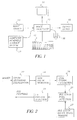
- Fig. 1 shows an image processing system useful in practicing the present invention including a color digital image source 10, such as a film scanner, digital camera, or digital image storage device such as a compact disk drive with a Picture CD.
- the digital image from the digital image source 10 is provided to an image processor 12 , such as a programmable personal computer, or digital image processing work station such as a Sun Sparc workstation.
- the image processor 12 may be connected to a CRT display 14 , an operator interface such as a keyboard 16 and a mouse 18 .
- Image processor 12 is also connected to computer readable storage medium 17 .
- the image processor 12 transmits processed digital images to an output device 19 .
- Output device 19 can comprise a hard copy printer, a long-term image storage device, a connection to another processor, or an image telecommunication device connected for example to the internet.
- the present invention comprises a computer program product for detecting human eyes and irises in a digital image in accordance with the method described.
- the computer program of the present invention can be utilized by any well-known computer system, such as the personal computer of the type shown in Fig. 1.
- many other types of computer systems can be used to execute the computer program of the present invention. Consequently, the computer system will not be discussed in further detail herein.
- the computer program product of the present invention may make use of image manipulation algorithms and processes that are well known. Accordingly, the present description will be directed in particular to those algorithms and processes forming part of, or cooperating more directly with, the method of the present invention. Thus, it will be understood that the computer program product embodiment of the present invention may embody algorithms and processes not specifically shown or described herein that are useful for implementation. Such algorithms and processes are conventional and within the ordinary skill in such arts.
- the computer program for performing the method of the present invention may be stored in a computer readable storage medium.
- This medium may comprise, for example; magnetic storage media such as a magnetic disk (such as a hard drive or a floppy disk) or magnetic tape; optical storage media such as an optical disc, optical tape, or machine readable bar code; solid state electronic storage devices such as random access memory (RAM), or read only memory (ROM); or any other physical device or medium employed to store a computer program.
- the computer program for performing the method of the present invention may also be stored on computer readable storage medium that is connected to the image processor by way of the internet or other communication medium. Those skilled in the art will readily recognize that the equivalent of such a computer program product may also be constructed in hardware.
- FIG. 2 is a flow chart illustrating one embodiment of the iris detection method of the present invention.
- iris detection is accomplished by first detecting skin colored regions in the image and then identifying iris pixels from the skin colored regions.
- the first step in skin color detection is color histogram equalization shown in Fig. 2 as step 22.
- Color Histogram Equalization step 22 receives images to be processed and ensures that the images are in a form that will permit skin color detection. This step is made necessary because human skin may take on any number of colors in an image because of lighting conditions, flash settings or other circumstances. This makes it difficult to automatically detect skin in such images.
- Color Histogram Equalization step 22 a statistical analysis of each image is performed. If the statistical analysis suggests that the image may contain regions of skin that have had their appearance modified by lighting conditions, flash settings or other circumstances then such images are modified so that skin colored regions can be detected.
- the image is searched for skin color regions in Skin Color Detection step 24 .
- a preferred method for detecting skin in a digital image is to separated skin color pixels from other pixels in an image by defining a working color space that contains a range of possible skin colors collected from a large population of images. A pixel is then identified as skin color pixel if the pixel has a color that is within the working color space.
- Skin Color Detection step 24 identifies a region of skin color pixels in the image. This region can be defined in any number of ways. In one embodiment, the skin color region is defined by generating a set of pixel locations identifying the pixels in the image having skin colors. In another embodiment, a modified image is generated that contains only skin color pixels. In yet another embodiment, Skin Color Detection step 24 defines boundaries that confine the skin color region in the image. It will be recognized that more than one skin color region can be identified in the image.
- Oval Region Extraction step 26 examines the skin color regions detected by the Skin Color Detection step 24 to locate skin color regions that may be indicative of a face. Because the human face has a roughly oval shape, the skin color regions are examined to locate an oval shaped skin color region. When an oval shaped skin color region is found, the Oval Region Extraction step 26 measures the geometric properties of the oval shaped skin color region. The Oval Region Extraction step 26 uses these measurements to define parameters that describe the size of the face and the location of the face within the image.
- Fig. 3 is an illustration of the relationship between the geometric parameters used to define an oval shaped skin color region in the image. As is shown in Fig. 3, these parameters include Oval_top 300, Oval_bottom 302, Oval_left 304, Oval_right 306, Oval_center_row 308, and Oval_center_column 310. These parameters are can be used in subsequent processing of the image. It will be recognized that the method of the present invention can be practiced using skin color detection regions that have shapes that are other than oval and that other geometric parameters can be defined in association with such shapes. It will also be recognized that it is not necessary to detect an oval or other shaped area in the image. In such case, the skin color region is examined to detect iris color pixels . Further, in such a case, still other parameters describing the skin color region are defined for use in the eye detection process.
- Iris Color Pixel Detection step 28 examines the pixels in the oval shaped skin color region to detect iris color pixels. In the method of the present invention, Iris Color Pixel Detection step 28 determines whether a pixel is an iris by measuring the red intensity of the pixel. Red intensity levels are measured because it has been observed that that a human iris has a low red intensity level as compared to human skin which has a relatively high red intensity level. However, the method of the present invention does not use a red level thresholding method to determine whether a pixel is to be classified as an iris or as a non-iris.
- the present invention classifies a pixel as an iris or a non-iris pixel on the basis of a probability analysis.
- This probability analysis applies an iris statistical model and a non-iris statistical model.
- the iris statistical model defines the probability that a given pixel is an iris pixel based upon the red intensity level of the pixel.
- the non-iris statistical model defines the probability that a given pixel is not an iris pixel based upon the red intensity level of the pixel.
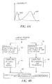
- the relationship between these models is non-linear as is shown by way of example in Fig.
- conditional probability 402 which is an illustration of the conditional probability 402 that a given pixel is an iris pixel stated as a function of a specific red intensity and the conditional probability 404 that a given pixel is a non-iris pixel as a function of a specific red intensity I.
- the probability analysis can take many forms.
- the probabilities can be combined in various ways with a pixel being classified as an iris or not on the basis of the relationship between these probabilities.
- a mathematical construct known as a Bayes model is used to combine the probabilities to produce the conditional probability that a pixel having a given red intensity belongs to an iris.
- the Bayes model is applied as follows: P ( iris
- I ) P ( I
- the Bayes model further applies the probability of the occurrence of an iris in a face oval region and the probability of the occurrence of a non-iris pixel in the face oval region.
- a probability analysis based on the Bayes model, a pixel is classified as an iris if the conditional probability that a pixel having a given red intensity belongs to an iris is greater than, for example, 0.05.
- Fig. 4a shows a flow chart illustrating the processes used in the Iris Color/Bayes Model Training step 27 of Fig. 2 for developing the statistical models used to classify the pixels. This step will be performed before the method for detecting irises is used to detect iris pixels. As is shown, a large sample of frontal face images are collected and examined. All iris pixels and non-iris pixels in the face region of each image are then manually identified 40, 42 .
- iris ) is computed and the probability of the occurrence of an iris in the face oval region, P ( iris ) 44 is computed; then the conditional probability that a given noniris pixel has a specific red intensity I, P ( I
- the computed statistical models of iris and non-iris are used in the Bayes formula to produce the conditional probability that a given pixel intensity belongs to an iris, P ( iris
- the Bayes model can be used to generate a look-up table to be used in Iris Color Pixel Detection step 28 .
- the Iris Color Pixel Detection step 28 identifies the location of the iris color pixels in the image. In some cases, it will be desirable to ensure that the iris color pixels that are detected are associated with an eye. This is done by performing the step of eye detection. Eye Position Detection step 27 is used to estimate the eye positions. It will be appreciated that there are many ways to determine whether an iris pixel is associated with an eye in the image. In one preferred embodiment of the present invention, the iris color pixel locations are used to facilitate the process of determining whether an iris pixel is associated with an eye in the image.
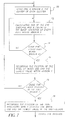
- Fig. 5 shows a flow chart illustrating the process of eye position detection using the iris color pixels.
- the eye position detection process starts with an Iris Pixel Clustering step 50 . If iris color pixels are detected, then the iris pixels must be assigned to a cluster.
- a cluster is a non-empty set of iris color pixels with the property that any pixel within the cluster is also within a predefined distance to another pixel in the cluster. One example of a predefined distance is one thirtieth of the digital image height.
- the Iris Pixel Clustering step 50 of Fig. 5 groups iris color pixels into clusters based upon this definition of a cluster. However, it will be understood that pixels may be clustered on the basis of other criteria.
- a cluster of pixels may not be valid. Accordingly, the optional step of validating the clusters is shown in Fig. 5 as Cluster Validation step 51 .
- a cluster may be invalid because, if it contains too many iris color pixels or because the geometric relationship of the pixels in the cluster suggests that the cluster is not indicative of an iris. For example, if the ratio is greater than two, then this cluster is invalid.
- Invalid iris pixel clusters are removed from further consideration by the method of the present invention. Accordingly, in the portions of the description that follow, valid iris pixel clusters will be referred to simply as iris pixel clusters.
- a center for each of the clusters is calculated in Cluster Centering step 52 .
- the center of a cluster is determined as the center of mass of the cluster.
- the center position of the clusters is calculated with respect to the origin of the image coordinate system.
- the origin of the image coordinate system for a digital image is defined is at the upper left corner of the image boundary.
- Oval division step 54 uses the Oval_center_column 310 parameter to separate the oval shaped skin color region into a left-half region and a right-half region. As is shown in Fig. 6 iris pixel clusters 602 and the center positions 600 of the iris pixel clusters 602 are positioned in either the left-half or right-half regions 604 and 606 separated by the Oval_Center_Column 310.
- a left-eye position search 56 is conducted in the left-half region using a method known as the Summation of the Squared Difference.
- a right-eye position search 58 is also conducted in the right-half region based on the same Summation of the Squared Difference method.
- the summation of the squared difference method involves calculating the summation of the squared difference of the intensity values of the corresponding pixels in an eye template and a patch of the image that has the same size as the template.
- each pixel in the patch of pixels has a corresponding pixel in the template. The difference between the intensity level of each of the corresponding pixels is calculated. Each difference is then squared.
- the sum of each of the squared differences for each of the pixels in the set is then calculated. This summation of the squared differences provides a relative measure of the degree of correspondence between each of the pixel sets measured and the template.
- the eye template itself is generated by averaging a large number of sample eye images.
- summation of the squared difference values are calculated for each pixel in each window in each half-region. These values are compared and the pixel having the lowest relative summation of the squared difference value is identified as an eye location for the half-region. This process is performed separately on the clusters of the left and the right-half regions of the image in the manner described below.
- the present invention has been described as using the summation of the squared difference method to identify the best relative match between the average eye template and each of the pixels, other methods to determine the degree of relative correspondence can be used.
- the mean-squared error method can be used in place of the summation of the squared difference method.
- the eye position search process 56 or 58 is started with centering 70 a window 800 at the center of each cluster 802 in a respective half-region.
- the operation of calculating the summation of the squared differences 72 is then performed, separately, using a patch of pixels centered on each of the pixels in each of windows 74 .
- the position of the pixel having the lowest summation of squared difference value in each window 800 is recorded 76 .
- this process has been completed for every cluster center 802 in a half region 78 , the position of the pixel having the lowest summation of squared difference value is recorded 79 . This position is the eye position for the half-region.
- the summation of the squared difference method of steps 56 and 58 of Fig. 5 can also be performed without the use of oval region extraction.
- the skin colored region can be divided into a left-half region and a right-half region.
- Iris pixel clusters can then be divided into left-half region and right-half region clusters.
- the summation of the squared difference method can then be applied.
- the subject matter of the present invention relates to digital image understanding technology, which is understood to mean technology that digitally processes a digital image to recognize and thereby assign useful meaning to human understandable objects, attributes or conditions and then to utilize the results obtained in the further processing of the digital image.
- the present invention provides an efficient method for detecting normally appearing human irises in a digital image.
Landscapes
- Engineering & Computer Science (AREA)
- General Physics & Mathematics (AREA)
- Theoretical Computer Science (AREA)
- General Health & Medical Sciences (AREA)
- Human Computer Interaction (AREA)
- Physics & Mathematics (AREA)
- Health & Medical Sciences (AREA)
- Multimedia (AREA)
- Ophthalmology & Optometry (AREA)
- Oral & Maxillofacial Surgery (AREA)
- Image Analysis (AREA)
- Measurement Of The Respiration, Hearing Ability, Form, And Blood Characteristics Of Living Organisms (AREA)
- Image Processing (AREA)
- Facsimile Image Signal Circuits (AREA)
- Color Image Communication Systems (AREA)
Abstract
Description
Claims (10)
- A digital image processing method for detecting human irises in a digital image formed from pixels, the method comprising the steps of:measuring a red intensity of the pixels in the image;determining a probability that each pixel is an iris based upon the red intensity of the pixel;determining a probability that each pixel is not an iris based upon the red intensity of the pixel; anddetermining whether each pixel is an iris by analyzing the relationship between the probability that the pixel is an iris and probability that the pixel is not an iris.
- The method of claim 1, wherein the step of determining whether each pixel is an iris is based upon the application of a Bayes model to the probability that the pixel is an iris, the probability that a pixel is not an iris, the probability of the occurrence of a non-iris pixel in the image and the probability of the occurrence of a non-iris pixel in the image.
- The method of claim 1 further comprising the step of detecting skin color regions in the image and wherein the step of measuring the red intensity comprises measuring the red intensity of only the pixels in the skin color region.
- The method of claim 3 further comprising the step of performing color equalization on the image prior to the step of detecting skin color regions in the image.
- The method of claim 4 wherein the step of determining whether each pixel is an iris is based upon the application of a Bayes model to the probability that the pixel is an iris, the probability that the pixel is not an iris, the probability of the occurrence of an iris in a skin color region, and the probability of the occurrence of a non-iris pixel in a skin color region.
- The method of claim 4 further comprising the step of finding oval shaped skin colored regions in the image and wherein the step of measuring the red intensity of the pixels in the skin color region comprises measuring only those pixel within an oval shaped skin color region.
- The method of claim 6 wherein the step of determining whether each pixel is an iris is based upon the application of a Bayes model to the probability that the pixel is an iris, the probability that the pixel is not an iris, the probability of the occurrence of an iris in an oval shaped skin color region, and the probability of the occurrence of a non-iris pixel in an oval shaped skin color region.
- A computer program product for detecting human irises and eyes in a digital image, the computer program product comprising a computer readable storage medium having a computer program stored thereon for performing the steps of:finding a skin colored region;detecting iris color pixels in the skin colored region using a Bayes model; andlocating eye positions based upon the detected iris color pixels.
- The computer program product of claim 8, wherein the step of locating eye positions based upon the detected iris color pixels comprises the steps of:clustering iris color pixels;finding the center of each cluster;dividing the skin colored region into a left-half and a right-half;locating the most likely left eye position in the left-half region using the summation of squared difference method; andlocating the most likely right eye position in the right-half region using the summation of squared difference method.
- The computer program product of claim 9, wherein the step of locating the most likely left eye position is performed using the summation of squared difference method comprises the steps of:defining a window of pixels surrounding the center of each of the clusters in the image;dividing the iris pixel clusters into left-half iris pixel clusters and right-half pixel clusters; andlocating the most likely left eye position based on the summation of squared difference between an average eye and patch of the image centered at each of the pixels in each of the windows surrounding a left-half iris pixel cluster.
Applications Claiming Priority (2)
| Application Number | Priority Date | Filing Date | Title |
|---|---|---|---|
| US740422 | 2000-12-19 | ||
| US09/740,422 US6920237B2 (en) | 2000-12-19 | 2000-12-19 | Digital image processing method and computer program product for detecting human irises in an image |
Publications (2)
| Publication Number | Publication Date |
|---|---|
| EP1217572A2 true EP1217572A2 (en) | 2002-06-26 |
| EP1217572A3 EP1217572A3 (en) | 2004-01-14 |
Family
ID=24976433
Family Applications (1)
| Application Number | Title | Priority Date | Filing Date |
|---|---|---|---|
| EP01204728A Withdrawn EP1217572A3 (en) | 2000-12-19 | 2001-12-06 | Digital image processing method and computer program product for detecting human irises in an image |
Country Status (3)
| Country | Link |
|---|---|
| US (1) | US6920237B2 (en) |
| EP (1) | EP1217572A3 (en) |
| JP (1) | JP2002230547A (en) |
Cited By (3)
| Publication number | Priority date | Publication date | Assignee | Title |
|---|---|---|---|---|
| GB2389727A (en) * | 2002-05-03 | 2003-12-17 | Univ East Anglia | Histogram equalisation for colour invariance |
| WO2005119596A1 (en) * | 2004-05-27 | 2005-12-15 | Siemens Corporate Research, Inc. | Graphical object models for detection and tracking |
| CN108629293A (en) * | 2018-04-16 | 2018-10-09 | 西安交通大学 | A kind of adaptive near-infrared iris image acquiring method with feedback mechanism |
Families Citing this family (39)
| Publication number | Priority date | Publication date | Assignee | Title |
|---|---|---|---|---|
| US6859550B2 (en) * | 2001-05-31 | 2005-02-22 | Seho Oh | Robust method for image feature estimation |
| US7058209B2 (en) * | 2001-09-20 | 2006-06-06 | Eastman Kodak Company | Method and computer program product for locating facial features |
| AUPS140502A0 (en) * | 2002-03-27 | 2002-05-09 | Seeing Machines Pty Ltd | Method for automatic detection of facial features |
| KR100474848B1 (en) * | 2002-07-19 | 2005-03-10 | 삼성전자주식회사 | System and method for detecting and tracking a plurality of faces in real-time by integrating the visual ques |
| TWI224287B (en) * | 2003-01-23 | 2004-11-21 | Ind Tech Res Inst | Iris extraction method |
| US6912298B1 (en) * | 2003-08-11 | 2005-06-28 | Adobe Systems Incorporation | Object detection using dynamic probability scans |
| US7664322B1 (en) * | 2003-08-11 | 2010-02-16 | Adobe Systems Incorporated | Feature-based color adjustment |
| US8045764B2 (en) | 2005-01-26 | 2011-10-25 | Honeywell International Inc. | Expedient encoding system |
| US8098901B2 (en) | 2005-01-26 | 2012-01-17 | Honeywell International Inc. | Standoff iris recognition system |
| US8049812B2 (en) | 2006-03-03 | 2011-11-01 | Honeywell International Inc. | Camera with auto focus capability |
| US8442276B2 (en) | 2006-03-03 | 2013-05-14 | Honeywell International Inc. | Invariant radial iris segmentation |
| US7593550B2 (en) | 2005-01-26 | 2009-09-22 | Honeywell International Inc. | Distance iris recognition |
| US8090157B2 (en) | 2005-01-26 | 2012-01-03 | Honeywell International Inc. | Approaches and apparatus for eye detection in a digital image |
| US8705808B2 (en) | 2003-09-05 | 2014-04-22 | Honeywell International Inc. | Combined face and iris recognition system |
| US8064647B2 (en) | 2006-03-03 | 2011-11-22 | Honeywell International Inc. | System for iris detection tracking and recognition at a distance |
| US7295686B2 (en) * | 2003-09-29 | 2007-11-13 | Primax Electronics Ltd. | Method of processing red eye in digital images |
| FR2864290B1 (en) * | 2003-12-18 | 2006-05-26 | Sagem | METHOD AND DEVICE FOR RECOGNIZING IRIS |
| JP4511850B2 (en) * | 2004-03-03 | 2010-07-28 | 学校法人早稲田大学 | Person attribute identification method and system |
| US7627148B2 (en) * | 2004-07-06 | 2009-12-01 | Fujifilm Corporation | Image data processing apparatus and method, and image data processing program |
| JP4328286B2 (en) * | 2004-12-14 | 2009-09-09 | 本田技研工業株式会社 | Face area estimation device, face area estimation method, and face area estimation program |
| US7809171B2 (en) * | 2005-01-10 | 2010-10-05 | Battelle Memorial Institute | Facial feature evaluation based on eye location |
| US7676063B2 (en) * | 2005-03-22 | 2010-03-09 | Microsoft Corp. | System and method for eye-tracking and blink detection |
| AU2007220010B2 (en) | 2006-03-03 | 2011-02-17 | Gentex Corporation | Single lens splitter camera |
| WO2007103834A1 (en) | 2006-03-03 | 2007-09-13 | Honeywell International, Inc. | Indexing and database search system |
| GB2450024B (en) | 2006-03-03 | 2011-07-27 | Honeywell Int Inc | Modular biometrics collection system architecture |
| WO2008016724A2 (en) | 2006-03-03 | 2008-02-07 | Honeywell International, Inc. | An iris recognition system having image quality metrics |
| US8063889B2 (en) | 2007-04-25 | 2011-11-22 | Honeywell International Inc. | Biometric data collection system |
| JP4663699B2 (en) * | 2007-09-27 | 2011-04-06 | 富士フイルム株式会社 | Image display device and image display method |
| US8436907B2 (en) | 2008-05-09 | 2013-05-07 | Honeywell International Inc. | Heterogeneous video capturing system |
| US8050494B2 (en) * | 2008-05-23 | 2011-11-01 | Samsung Electronics Co., Ltd. | System and method for human hand motion detection by skin color prediction |
| US8213782B2 (en) | 2008-08-07 | 2012-07-03 | Honeywell International Inc. | Predictive autofocusing system |
| US8090246B2 (en) | 2008-08-08 | 2012-01-03 | Honeywell International Inc. | Image acquisition system |
| US8280119B2 (en) | 2008-12-05 | 2012-10-02 | Honeywell International Inc. | Iris recognition system using quality metrics |
| US8630464B2 (en) | 2009-06-15 | 2014-01-14 | Honeywell International Inc. | Adaptive iris matching using database indexing |
| US8472681B2 (en) | 2009-06-15 | 2013-06-25 | Honeywell International Inc. | Iris and ocular recognition system using trace transforms |
| US8742887B2 (en) | 2010-09-03 | 2014-06-03 | Honeywell International Inc. | Biometric visitor check system |
| US9378564B2 (en) * | 2013-03-01 | 2016-06-28 | Colormodules Inc. | Methods for color correcting digital images and devices thereof |
| CN106530268A (en) * | 2015-09-08 | 2017-03-22 | 普瑞斯康(北京)健康管理有限公司 | Diagnosing device and method |
| CN107451533B (en) * | 2017-07-07 | 2020-06-30 | Oppo广东移动通信有限公司 | Control method, control device, electronic device, and computer-readable storage medium |
Family Cites Families (30)
| Publication number | Priority date | Publication date | Assignee | Title |
|---|---|---|---|---|
| US4641349A (en) * | 1985-02-20 | 1987-02-03 | Leonard Flom | Iris recognition system |
| US5128711A (en) * | 1989-04-28 | 1992-07-07 | Fuji Photo Film Co., Ltd. | Apparatus for recording position information of principal image and method of detecting principal image |
| US5130789A (en) * | 1989-12-13 | 1992-07-14 | Eastman Kodak Company | Localized image recoloring using ellipsoid boundary function |
| US5089976A (en) * | 1990-07-18 | 1992-02-18 | Friends Of The Ucsd Library, Inc. | Color normalization process |
| JP2973676B2 (en) * | 1992-01-23 | 1999-11-08 | 松下電器産業株式会社 | Face image feature point extraction device |
| US5432863A (en) * | 1993-07-19 | 1995-07-11 | Eastman Kodak Company | Automated detection and correction of eye color defects due to flash illumination |
| US6095989A (en) * | 1993-07-20 | 2000-08-01 | Hay; Sam H. | Optical recognition methods for locating eyes |
| EP0865637A4 (en) | 1995-12-04 | 1999-08-18 | Sarnoff David Res Center | Wide field of view/narrow field of view recognition system and method |
| US5675376A (en) * | 1995-12-21 | 1997-10-07 | Lucent Technologies Inc. | Method for achieving eye-to-eye contact in a video-conferencing system |
| JPH09216580A (en) | 1996-02-14 | 1997-08-19 | Yamaha Motor Co Ltd | Truck bed floor structure |
| JP2907120B2 (en) * | 1996-05-29 | 1999-06-21 | 日本電気株式会社 | Red-eye detection correction device |
| US6144754A (en) * | 1997-03-28 | 2000-11-07 | Oki Electric Industry Co., Ltd. | Method and apparatus for identifying individuals |
| US6204858B1 (en) * | 1997-05-30 | 2001-03-20 | Adobe Systems Incorporated | System and method for adjusting color data of pixels in a digital image |
| US6381345B1 (en) * | 1997-06-03 | 2002-04-30 | At&T Corp. | Method and apparatus for detecting eye location in an image |
| JP3436473B2 (en) * | 1997-06-20 | 2003-08-11 | シャープ株式会社 | Image processing device |
| US6009209A (en) * | 1997-06-27 | 1999-12-28 | Microsoft Corporation | Automated removal of red eye effect from a digital image |
| KR19990016896A (en) * | 1997-08-20 | 1999-03-15 | 전주범 | Eye region detection method in face image |
| US6151403A (en) | 1997-08-29 | 2000-11-21 | Eastman Kodak Company | Method for automatic detection of human eyes in digital images |
| US6292574B1 (en) * | 1997-08-29 | 2001-09-18 | Eastman Kodak Company | Computer program product for redeye detection |
| US6407777B1 (en) * | 1997-10-09 | 2002-06-18 | Deluca Michael Joseph | Red-eye filter method and apparatus |
| US6016354A (en) * | 1997-10-23 | 2000-01-18 | Hewlett-Packard Company | Apparatus and a method for reducing red-eye in a digital image |
| WO1999023600A1 (en) | 1997-11-04 | 1999-05-14 | The Trustees Of Columbia University In The City Of New York | Video signal face region detection |
| US5953440A (en) * | 1997-12-02 | 1999-09-14 | Sensar, Inc. | Method of measuring the focus of close-up images of eyes |
| JP3271750B2 (en) * | 1998-03-05 | 2002-04-08 | 沖電気工業株式会社 | Iris identification code extraction method and device, iris recognition method and device, data encryption device |
| JP3549725B2 (en) * | 1998-04-13 | 2004-08-04 | シャープ株式会社 | Image processing device |
| US6394557B2 (en) * | 1998-05-15 | 2002-05-28 | Intel Corporation | Method and apparatus for tracking an object using a continuously adapting mean shift |
| US6631208B1 (en) * | 1998-05-29 | 2003-10-07 | Fuji Photo Film Co., Ltd. | Image processing method |
| US6353679B1 (en) * | 1998-11-03 | 2002-03-05 | Compaq Computer Corporation | Sample refinement method of multiple mode probability density estimation |
| US6639998B1 (en) * | 1999-01-11 | 2003-10-28 | Lg Electronics Inc. | Method of detecting a specific object in an image signal |
| US6697502B2 (en) * | 2000-12-14 | 2004-02-24 | Eastman Kodak Company | Image processing method for detecting human figures in a digital image |
-
2000
- 2000-12-19 US US09/740,422 patent/US6920237B2/en not_active Expired - Lifetime
-
2001
- 2001-12-06 EP EP01204728A patent/EP1217572A3/en not_active Withdrawn
- 2001-12-14 JP JP2001381418A patent/JP2002230547A/en active Pending
Cited By (7)
| Publication number | Priority date | Publication date | Assignee | Title |
|---|---|---|---|---|
| GB2389727A (en) * | 2002-05-03 | 2003-12-17 | Univ East Anglia | Histogram equalisation for colour invariance |
| GB2389727B (en) * | 2002-05-03 | 2006-08-02 | Univ East Anglia | Histogram equalisation for colour invariance |
| US8103097B2 (en) | 2002-05-03 | 2012-01-24 | Apple Inc. | Colour invariant image representation method and apparatus |
| US8467605B2 (en) | 2002-05-03 | 2013-06-18 | Apple Inc. | Color invariant image representation method and apparatus |
| WO2005119596A1 (en) * | 2004-05-27 | 2005-12-15 | Siemens Corporate Research, Inc. | Graphical object models for detection and tracking |
| US7436980B2 (en) | 2004-05-27 | 2008-10-14 | Siemens Corporate Research, Inc. | Graphical object models for detection and tracking |
| CN108629293A (en) * | 2018-04-16 | 2018-10-09 | 西安交通大学 | A kind of adaptive near-infrared iris image acquiring method with feedback mechanism |
Also Published As
| Publication number | Publication date |
|---|---|
| EP1217572A3 (en) | 2004-01-14 |
| US20020106112A1 (en) | 2002-08-08 |
| US6920237B2 (en) | 2005-07-19 |
| JP2002230547A (en) | 2002-08-16 |
Similar Documents
| Publication | Publication Date | Title |
|---|---|---|
| US6920237B2 (en) | Digital image processing method and computer program product for detecting human irises in an image | |
| US6792134B2 (en) | Multi-mode digital image processing method for detecting eyes | |
| US7092554B2 (en) | Method for detecting eye and mouth positions in a digital image | |
| US6895103B2 (en) | Method for automatically locating eyes in an image | |
| US5450504A (en) | Method for finding a most likely matching of a target facial image in a data base of facial images | |
| EP1296279B1 (en) | Method and computer program product for locating facial features | |
| US7035461B2 (en) | Method for detecting objects in digital images | |
| US7444017B2 (en) | Detecting irises and pupils in images of humans | |
| US8295593B2 (en) | Method of detecting red-eye objects in digital images using color, structural, and geometric characteristics | |
| US7764846B2 (en) | Adaptive red eye correction | |
| JP2002305667A (en) | Method and device for automatically correcting color defect | |
| US7570815B2 (en) | Comparing patterns | |
| US7657086B2 (en) | Method and apparatus for automatic eyeglasses detection using a nose ridge mask | |
| CN118864605A (en) | A target recognition and positioning system based on image segmentation and its terminal device | |
| US20070189609A1 (en) | Method, apparatus, and program for discriminating faces | |
| CN118115937A (en) | An item movement monitoring management system and method | |
| RU2329535C2 (en) | Method of automatic photograph framing | |
| JP2006309714A (en) | Face discrimination method and device, and program | |
| Marchesotti et al. | Safe red-eye correction plug-in using adaptive methods |
Legal Events
| Date | Code | Title | Description |
|---|---|---|---|
| PUAI | Public reference made under article 153(3) epc to a published international application that has entered the european phase |
Free format text: ORIGINAL CODE: 0009012 |
|
| AK | Designated contracting states |
Kind code of ref document: A2 Designated state(s): AT BE CH CY DE DK ES FI FR GB GR IE IT LI LU MC NL PT SE TR |
|
| AX | Request for extension of the european patent |
Free format text: AL;LT;LV;MK;RO;SI |
|
| PUAL | Search report despatched |
Free format text: ORIGINAL CODE: 0009013 |
|
| AK | Designated contracting states |
Kind code of ref document: A3 Designated state(s): AT BE CH CY DE DK ES FI FR GB GR IE IT LI LU MC NL PT SE TR |
|
| AX | Request for extension of the european patent |
Extension state: AL LT LV MK RO SI |
|
| 17P | Request for examination filed |
Effective date: 20040611 |
|
| AKX | Designation fees paid |
Designated state(s): DE FR GB |
|
| 17Q | First examination report despatched |
Effective date: 20040913 |
|
| GRAP | Despatch of communication of intention to grant a patent |
Free format text: ORIGINAL CODE: EPIDOSNIGR1 |
|
| STAA | Information on the status of an ep patent application or granted ep patent |
Free format text: STATUS: THE APPLICATION IS DEEMED TO BE WITHDRAWN |
|
| 18D | Application deemed to be withdrawn |
Effective date: 20060627 |