EP1217495A2 - Force feedback functioning manual input device and onboard instrument control system having it - Google Patents
Force feedback functioning manual input device and onboard instrument control system having it Download PDFInfo
- Publication number
- EP1217495A2 EP1217495A2 EP01130340A EP01130340A EP1217495A2 EP 1217495 A2 EP1217495 A2 EP 1217495A2 EP 01130340 A EP01130340 A EP 01130340A EP 01130340 A EP01130340 A EP 01130340A EP 1217495 A2 EP1217495 A2 EP 1217495A2
- Authority
- EP
- European Patent Office
- Prior art keywords
- input device
- manual input
- knob
- joystick type
- actuator
- Prior art date
- Legal status (The legal status is an assumption and is not a legal conclusion. Google has not performed a legal analysis and makes no representation as to the accuracy of the status listed.)
- Withdrawn
Links
Images




Classifications
-
- G—PHYSICS
- G05—CONTROLLING; REGULATING
- G05G—CONTROL DEVICES OR SYSTEMS INSOFAR AS CHARACTERISED BY MECHANICAL FEATURES ONLY
- G05G9/00—Manually-actuated control mechanisms provided with one single controlling member co-operating with two or more controlled members, e.g. selectively, simultaneously
- G05G9/02—Manually-actuated control mechanisms provided with one single controlling member co-operating with two or more controlled members, e.g. selectively, simultaneously the controlling member being movable in different independent ways, movement in each individual way actuating one controlled member only
- G05G9/04—Manually-actuated control mechanisms provided with one single controlling member co-operating with two or more controlled members, e.g. selectively, simultaneously the controlling member being movable in different independent ways, movement in each individual way actuating one controlled member only in which movement in two or more ways can occur simultaneously
- G05G9/047—Manually-actuated control mechanisms provided with one single controlling member co-operating with two or more controlled members, e.g. selectively, simultaneously the controlling member being movable in different independent ways, movement in each individual way actuating one controlled member only in which movement in two or more ways can occur simultaneously the controlling member being movable by hand about orthogonal axes, e.g. joysticks
-
- G—PHYSICS
- G05—CONTROLLING; REGULATING
- G05G—CONTROL DEVICES OR SYSTEMS INSOFAR AS CHARACTERISED BY MECHANICAL FEATURES ONLY
- G05G9/00—Manually-actuated control mechanisms provided with one single controlling member co-operating with two or more controlled members, e.g. selectively, simultaneously
- G05G9/02—Manually-actuated control mechanisms provided with one single controlling member co-operating with two or more controlled members, e.g. selectively, simultaneously the controlling member being movable in different independent ways, movement in each individual way actuating one controlled member only
- G05G9/04—Manually-actuated control mechanisms provided with one single controlling member co-operating with two or more controlled members, e.g. selectively, simultaneously the controlling member being movable in different independent ways, movement in each individual way actuating one controlled member only in which movement in two or more ways can occur simultaneously
- G05G9/047—Manually-actuated control mechanisms provided with one single controlling member co-operating with two or more controlled members, e.g. selectively, simultaneously the controlling member being movable in different independent ways, movement in each individual way actuating one controlled member only in which movement in two or more ways can occur simultaneously the controlling member being movable by hand about orthogonal axes, e.g. joysticks
- G05G2009/04766—Manually-actuated control mechanisms provided with one single controlling member co-operating with two or more controlled members, e.g. selectively, simultaneously the controlling member being movable in different independent ways, movement in each individual way actuating one controlled member only in which movement in two or more ways can occur simultaneously the controlling member being movable by hand about orthogonal axes, e.g. joysticks providing feel, e.g. indexing means, means to create counterforce
Definitions
- This invention relates to a force feedback functioning manual input device and an onboard instrument control system having it, and more particularly relates to an input means that is rendered multifunctional and a technique for integration of the input means.
- a force feedback functioning manual input device has been known that gives resistant sensation and thrust to a knob corresponding to the operation magnitude and operation direction so that the operation feeling of the knob, which is served as an input means, is rendered realistic for making the knob operation sure.
- the manual input device of the present example comprises a rotary knob 101, a detection means 102 for detecting the rotation magnitude and rotation direction of the rotary knob 101, an actuator 103 for loading an external force on the rotary knob 101, a control unit 104 for taking in a detection signal a supplied from the detection means 102 and for generating a control signal c to operate the actuator 103, a D/A converter 105 for D/A converting a control signal c generated from the control unit 104, and a power amplifier 106 for amplifying a control signal c that has been converted to an analog signal by means of the D/A converter 105 to obtain the power for driving the actuator 103.
- the control unit 104 has a CPU 104a and a memory 104b, and the memory 104b has stored the control signal c corresponding to the detection signal a in the form of a table.
- the CPU 104a takes in a detection signal a from the detection means 102, reads out a control signal c corresponding to the taken-in detection signal a from the memory 104b, and supplies it to the D/A converter 105.
- the actuator 103 is driven, the force feedback corresponding to the operation magnitude and operation direction is transmitted to the rotary knob 101.
- the manual input device of this example is excellent in the operation feeling of the rotary knob 101, and the rotary knob 101 can be operated consistently.
- a manual input device of this type is applied to a by-wire gear shift unit of an automobile and various onboard electric instrument such as an air conditioner, a radio, a television set, a CD player, and a navigation system as the function control system.
- various onboard electric instrument such as an air conditioner, a radio, a television set, a CD player, and a navigation system as the function control system.
- the force feedback function provides a click feeling when a shift lever range is changed, and used as a lock means for inhibiting incorrect operation of a shift lever from a specific range to another specific range such as shift from P (parking) range to R (reverse) range and shift from D (drive) range to 2nd (second) range.
- the force feedback function of a manual input device provides a suitable resistance feeling to a rotary knob 101 to make the fine adjustment of the function easy, or provides a suitable thrust to a rotary knob 101 to make operation of the rotary knob light.
- the manual input device provided with the rotary knob 101 is described as an example in the above, however in addition to the abovementioned rotary knob 101, a manual input device provided with a joystick type knob that is swingable in two-dimensional direction and a manual input device provided with a lever-type knob that is turned in a certain plane have been known conventionally.
- an exemplary manual input device shown in FIG. 9 is applied as a function control system for controlling onboard instruments, so many instruments to be controlled are mounted and so many functions to be controlled should be involved. If a system is designed so that the function of all the onboard instruments is controlled with only one rotation knob 101, the operability of the system is poor and the system leads to wrong operation. On the other hand, if a plurality of manual input devices are deployed on an onboard instrument control system in parallel, the manual input devices need a large space and the onboard instrument system is rendered large-sized, and such an onboard instrument control system will be expensive.
- the present invention has been accomplished to solve the abovementioned conventional technique, and it is an object of the present invention to provide a small-sized and low-cost manual input device excellent in operability and multifunctionality, and to provide a small-sized and low cost onboard instrument control system provided with a manual input device of this type that is excellent in operability and multifunctionality.
- a manual input device is provided with a joystick type knob and a rotary knob that are disposed coaxially, one first actuator for loading an external force on the joystick type knob, one second actuator for loading an external force on the rotary knob, first detection means for detecting an operation state of the joystick type knob, and second detection means for detecting an operation state of the rotary knob.
- the manual input device provided with the joystick type knob and the rotary knob allows use of a plurality of knobs properly corresponding to an electric instrument and function that are to be controlled as described hereinabove, the operability of the manual input device is improved and the manual input device is rendered multifunctional. Furthermore, because the coaxial arrangement of the knobs allows the knobs to be disposed intensively on a limited space, the small-sized input device is realized.
- the structure that one first actuator loads a force feedback external force on the joystick type knob allows the number of actuators of the manual input device to be minimized, it is possible to configure the manual input device intensively in comparison with the case where two or more actuators load a force feedback external force on the joystick type knob, and a small-sized, low-cost, and power saving manual input device can be realized.
- the manual input device of the present invention is provided with a guide member for defining an operation direction of the joystick type knob.
- the joystick type knob is operated only in a predetermined direction because of the guide member, and the signal input operation can be operated easily and consistently by use of the joystick type knob.
- a control unit that controls the first actuator based on a signal supplied from the first detection means and controls the second actuator based on a signal supplied from the second detection means is provided combinedly in a box that constitutes the manual input device.
- control unit of the first and second actuators is provided combinedly in the box that constitutes the manual input device and it is not necessary to change an external apparatus, the manual input device can be applied easily to an external apparatus.
- a control unit that controls the first actuator based on a signal supplied from the first detection means and that controls the second actuator based on a signal supplied from the second detection means is provided in an external apparatus.
- control unit of the first and second actuators is provided in an external apparatus and the control unit can be omitted from the manual input device thereby, a small-sized and low-cost manual input device can be realized.
- an onboard instrument control device has electric instrument selection switches for selecting an electric instrument the function of which is to be controlled and a manual input device for controlling various functions of the electric instrument selected by use of one of the selection switches, wherein the onboard instrument control device is provided with the manual input device having a joystick type knob and a rotary knob that are disposed coaxially, a first actuator for loading an external force on the joystick type knob, a second actuator for loading an external force on the rotary knob, first detection means for detecting an operation state of the joystick type knob, and second detection means for detecting an operation state of the rotary knob.
- the onboard instrument control device is provided with electric instrument selection switches for selecting an electric instrument the function of which is to be controlled and the manual input device for controlling various functions of the electric instrument selected by use of a selection switch and the function of many electric instruments can be controlled intensively by means of one onboard instrument control device, the function of various onboard electric instruments can be controlled easily and the driving safety performance of an automobile is improved. Furthermore, because a manual input device of an onboard instrument control device provided with a joystick type knob and rotary knob is used and the plurality of knobs can be used properly corresponding to an electric instrument or the function to be controlled, the operability of the onboard instrument control device is improved and the onboard instrument control device is rendered multifunctional.
- knobs are disposed coaxially and the space where the knobs are disposed is reduced, a small-sized onboard instrument control device is realized. Furthermore, because one first actuator loads a force feedback external force on the joystick type knob and the number of actuators to be provided in the onboard instrument control device is minimized thereby, the structure of the onboard instrument control device is intensified in comparison with the case where two or more first actuators load a force feedback external force on the joystick type knob and a small-sized, low-cost, and power-saving onboard instrument control device is realized.
- FIG. 1 is a partial cross sectional view viewing from the front direction of the manual input device of the present example
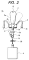
- FIG. 2 is a partial cross sectional view viewing from the side direction of the manual input device of the present example
- FIG. 3 is a view along the 3-3 line of FIG. 1
- FIG. 4 is a perspective view showing the structure of a stick controller.
- the manual input device 1A of the present example is provided with a spherical shaft bearing 1, a joystick type knob 2 held swingably on the spherical shaft bearing 1, a rotary knob 3 disposed coaxially with the joystick type knob 2, a first actuator 4 for loading an external force on the joystick type knob 2, a second actuator 5 for loading an external force on the rotary knob 3, a control unit 6 for controlling these first and second actuators 4 and 5, a guide member 7 for defining the operation direction of the joystick type knob 2, a first detection means 8 for detecting the operation state of the joystick type knob 2, and a second detection means 9 for detecting the operation state of the rotary knob 3.
- the joystick type knob 2 comprises a holding portion 2a, a spherical portion 2b, a connection portion 2c and a bearing portion 2d, and the spherical portion 2b is held swingably by the spherical bearing 1.
- a push button switch 10 is provided on a portion of the holding portion 2a. When the push button switch 10 is operated at a desired timing after the holding portion 2a is operated, a signal generated from the first detection means 8 is settled.
- the connection portion 2c is inserted through a cross-shaped guide hole 7a formed on the guide member 7 as shown in FIG. 3, and the guide member 7 defines the operation direction and the operation range of the joystick type knob 2. Only the guide member 7 on which the cross-shaped guide hole 7a is formed is shown exemplarily in FIG.
- the configuration of the guide hole 7a is by no means limited to the abovementioned cross shape, for example, a guide hole 7a of an arbitrary configuration such as a joystick type knob 2 for guiding 6 or 8 directions may be formed.
- the connection portion 2c is connected to an operation lever 8a of the first detection means 8 with interposition of a link 11.
- a stick controller may be used as the first detection means 8.
- the stick controller (first detection means 8) comprises an operation lever 8a that is held swingably on a box 12, a converter 15 for converting the swing motion of the operation lever 8a to the rotation motion of two rotors 13 and 14 disposed orthogonally each other, and two rotary type encoders or variable resistors 15 and 16 for converting the rotation magnitude and rotation direction of the two rotors 13 and 14 to the electric signal, and the encoders or variable resistors 15 and 16 generate the first detection signal a1 corresponding to the swing magnitude and the swing direction of the holding portion 2a.
- the rotary knob 3 is shaped in the form of circular ball, and an internal tooth gear 3a is formed in the circumferential direction on the internal surface.
- the internal tooth gear 3a is engaged with a pinion 17 fixed to a drive shaft 9a of the second detection means 9.
- a rotary type encoder or variable resistor that is capable of converting the rotation magnitude and the rotation direction of the rotary knob 3 to the electric signal may be used as the second detection means 9, and the second detection means 9 generates a second detection signal a2 corresponding to the rotation magnitude and the rotation direction of the rotary knob 3.
- a voice coil motor such as a linear motor or solenoid may be used as the first actuator 4.
- the bearing portion 2d of the joystick type knob 2 is connected to the drive shaft 4a of the first actuator 4 with interposition of a first connection member 18 and a second connection member 19.
- the bearing portion 2d is shaped in the form of ball bearing, the one end of the first connection member 18 connected to the bearing portion 2d is shaped spherical, and the first connection member 18 is connected swingably to the joystick type knob 2.
- the second connection member 19 comprises a wire having pin joints 19a and 19b at both end portions, and the respective pin joints 19a and 19b are connected to the bottom portion of the first connection member 18 and the drive shaft 4a of the first actuator 4 by means of pin connection.
- the joystick type knob 2 is mechanically connected to the first actuator 4 normally regardless of the swinging magnitude and swinging direction of the joystick type knob 2, and the driving force of the first actuator 4 is loaded on the joystick type knob 2.
- the character 20 indicates a wire guide
- a roller 20a may be provided on the point end portion of the wire guide 20 for smooth motion of the second connection member 19.
- a rotation motor such as a DC motor or a stepping motor may be used as the second actuator 5.
- the control portion 6 comprises a CPU 6a and a memory 6b, and the memory 6b stores the data and program for analyzing the detection signals a1 and a2 and the driving data and driving program of the first and second actuators 4 and 5.
- the CPU 6a takes in the detection signals a1 and a2, analyzes the detection signals a1 and a2 based on the data and program stored in the memory 6b, decides control signals c1 and c2 corresponding to the detection signals a1 and a2 based on the data and program stored in the memory 6b, and supplies the control signals c1 and c2 to the first actuator 4 and second actuator 5.
- control portion 6 is connected to electric instruments (not shown in the drawings) to be subjected to function control by means of the manual input device 1A, generates a control signal d for an electric instrument corresponding to the detection signals a1 and a2, and thereby control the function of a desired electric instrument.
- the control portion 6 may be disposed in the manual input device 1A or may be provided in an external device.
- Control signals c1 and c2 are signals corresponding to the operation feeling provided to the knobs 2 and 3. Examples of signal types include “generation of vibration, "generation of shock force”, and “change of action force”. In the case where the signal type is “generation of vibration”, control signals c1 and c2 that express the vibration intensity, vibration form, load time, and frequency are generated. Furthermore, in the case where the signal type is "generation of shock force”, control signals c1 and c2 that express the shock intensity, shock form, and load frequency are generated. Furthermore, in the case where the signal type is "action force change”, control signals c1 and c2 that express the action force intensity, generation direction of an action force, and loading time are generated.
- a first detection signal a1 corresponding to the swing magnitude and swing direction of the joystick type knob 2 is generated from the encoders or variable resistors 15 and 16 of the stick controller (first detection means 8).
- the first detection signal a1 is taken in the CPU 6a, and converted to a control signal c1 of the first actuator 4 according to the data and program stored in the memory 6b.
- the first actuator 4 is driven by the control signal c1, and loads a particular external force on the joystick type knob 2 corresponding to the swing magnitude and swing direction of the joystick type knob 2.
- the CPU 6a generates a control signal d to select an electric instrument the function of which is to be controlled and to control the function of the selected electric instrument correspondingly to the first detection signal a1.
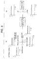
- FIG. 5 is a diagram for describing the action in the case where a joystick type knob 2 is applied for function selection and function control of an onboard air-conditioner.
- the joystick type knob 2 is inclined in a forward direction, a backward direction, a left direction, or a right direction from the center position to select the front defroster, rear defogger, temperature control, or air flow rate control respectively.
- the first detection signal a1 generated from the stick controller 8 is changed corresponding to the inclined magnitude and inclined direction of the joystick type knob 2.
- the CPU 6a takes in the first detection signal a1 and generates a control signal c1 corresponding to the first detection signal a1 to drive the first actuator, and then loads an external force of the desired mode on the joystick type knob 2.
- FIG. 5(a) Four graphs shown in FIG. 5(a) are graphs for exemplarily showing the relation between the inclination magnitude S1 of the joystick type knob 2 and the external force F exerted on the joystick type knob 2. As shown in these graphs, the external force F having different forms corresponding to the inclination direction of the joystick type knob 2 are loaded respectively on the joystick type knob 2. Thereby, an operator can recognize that the joystick type knob 2 is operated in the intended direction without viewing the joystick type knob 2.
- the selection of the front defroster, rear defogger, temperature control, or air flow rate control is settled finally by the push button switch 10, and the CPU 6a is connected to a selected electric instrument.
- the joystick type knob 2 is switched to the temperature control means of the air-conditioner.
- the joystick type knob 2 is inclined forward from the center position to increase the temperature or inclined backward from the center position to decrease the temperature.
- the CPU 6a takes in the first detection signal a1 generated from the stick controller 8, and generates a control signal c1 corresponding to the first detection signal a1.
- the control signal c1 drives the first actuator 4, and desired external forces exemplarily shown in the respective graphs shown in FIG. 5(b) are loaded on the joystick type knob 2.
- the mode of the external force used when the function of the air-conditioner is selected may be the same as or different from the mode of the external force used when the function of the air-conditioner is controlled with respect to the operation of the joystick type knob 2 in the same direction.
- FIG. 4 shows a different case.
- a method in which the function of an air-conditioner is selected by means of a joystick type knob 2 and the function of the air-conditioner is controlled by means of a rotary knob 3 may be employed. The operation of a rotary knob 3 will be described hereunder.
- the motion is transmitted to a drive shaft of the second detection means 9 with interposition of the internal tooth gear 3a and the pinion 17, and the second detection means 9 generates a second detection signal a2 corresponding to the rotation magnitude and the rotation direction of the rotary knob 3.
- the CPU 6a takes in the second detection signal a2, and converts it to a control signal c2 of the second actuator 5 according to the data and program stored in the memory 6b.
- the second actuator 5 is driven by the control signal c2, and loads a particular external force on the rotary knob 3 corresponding to the rotation magnitude and/or rotation direction of the rotary knob 3.
- the CPU 6a according to the second detection signal a2, selects an electric instrument the function of which is to be controlled and controls the function of the selected electric instrument.
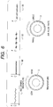
- FIG. 6 is a diagram for describing the case where a rotary knob 3 is applied to control the function of an onboard air-conditioner.
- the rotary knob 3 is turned left or right from the center position to increase the temperature of the air-conditioner or decrease the temperature of the air-conditioner, or to increase the air flow rate of the air-conditioner or decrease the air flow rate of the air-conditioner.
- the CPU 6a generates a control signal c2 corresponding to a second detection signal a2 that is different depending on the turning magnitude and turning direction of the rotary knob 3 to drive the second actuator 5, and loads an external force of a desired mode on the rotary knob 3 as shown in FIG. 6.
- FIG. 6 are graphs for exemplarily showing the relation between the turning magnitude S2 of the rotary knob 3 and the external force F that is exerted on the rotary knob 3.
- the external force that is different depending on the turning direction of the rotary knob 3 is loaded on the rotary knob 3.
- the mode of the external force used when the temperature of the air-conditioner is controlled may be the same as or different from the mode of the external force used when the air flow rate of the air-conditioner is controlled with respect to the operation of the rotary knob 3 in the same direction.
- FIG. 6 shows a different case.
- the application of the manual input device in accordance with the present invention is by no means limited to the above, for example, the present invention is applicable to various onboard electric instruments such as a radio, a television set, a CD player, a car navigation system, a handle tilting device, a seat attitude control unit, a telephone, a voice recognition device, and a gear shift device.
- a radio a radio, a television set, a CD player, a car navigation system, a handle tilting device, a seat attitude control unit, a telephone, a voice recognition device, and a gear shift device.
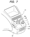
- FIG. 7 is a partial perspective view showing an onboard instrument control device in accordance with the present embodiment that is fixed on a dashboard
- FIG. 8 is a partial plan view showing the onboard instrument control device in accordance with the present embodiment including the state of the cabin of an automobile
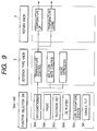
- FIG. 9 is a functional block diagram of the onboard instrument control device in accordance with the present embodiment.
- the onboard instrument control device 51 in accordance with the present embodiment is contained in a box 52 having a desired size that is formed in the shape of box, and a built-in manual input device 1A in accordance with the abovementioned embodiment is contained in the box 52, a joystick type knob 2 and a rotary knob 3 of the manual input device 1A are disposed above the box 52.
- Six push button switches 54a, 54b, 54c, 54d, 54e, and 54f disposed in the form of circular arc having the center at the setting portion of the knob 3 are disposed on the upper surface of the box 52, and a card slot 57 and a disc slot 58 are formed on the front surface of the box 52.
- the character D in the drawing shows a display device.
- the onboard instrument control device is fixed on the dashboard A of an automobile between the driver seat B and a front passenger seat C.
- the six push button switches 54a to 54f arranged in the form of circular arc are served as the electric instrument selection switch used for selecting an onboard electric instrument to be operated by use of the onboard instrument control device 51 of the present example such as an air-conditioner, a radio, a television set, a CD player, a car navigation system, a handle tilting device, a seat attitude control unit, a telephone, and a gear shift device, and connected to each onboard electric instrument separately.
- a push button switch may be connected arbitrarily to any one of the onboard electric instruments.
- the onboard instrument control device 51 of the present example as shown in FIG.
- the push button switch 54a is connected to the air conditioner
- the push button switch 54b is connected to the radio
- the push button switch 54c is connected to the television set
- the push button switch 54d is connected to the CD player
- the push button switch 54e is connected to the car navigation system
- the push button switch 54f is connected to the handle tilting device.
- the built-in manual input device 1A contained in the box 52 is used as the function control means of the onboard electric instrument selected correspondingly to the push button switches 54a to 54f, for example, in the case where the air-conditioner is selected correspondingly to the push button switch 55a, the joystick type knob 2 is operated to select the function such as front defroster, rear defogger, temperature control, or air flow rate, and the joystick type knob 2 or rotary knob 3 is operated to select the function such as temperature control or air flow rate control of the air-conditioner.
- the onboard instrument control device of the present example realizes the centralized control of a plurality of onboard electric instruments, the function of onboard electric instruments can be controlled easily, and the driving safety of the automobile is improved. Furthermore, because a manual input device having a plurality of knobs is used, these knobs can be used properly and correspondingly to the electric instrument to be controlled and the function, and the operability of the onboard instrument control device is improved and the onboard instrument control device is rendered multifunctional.
- the manual input device of the present invention is provided with a joystick type knob and a rotary knob both, knobs can be used properly and correspondingly to the instrument to be controlled and the function. As the result, the operability of the manual input device is improved and the manual input device is rendered multifunctional. Furthermore, because the manual input device of the present invention is provided with a plurality of knobs that are arranged coaxially, the space for the knobs can be centralized intensively and the small-sized manual input device is realized.
- the manual input device of the present invention has the structure that one first actuator loads the force feedback external force on the joystick type knob, the number of actuators to be provided on the manual input device is minimized and the structure of the manual input device is centralized intensively, and the small-sized, low-cost and power-saving manual input device is realized.
- the manual input device of the present invention is provided with a guide member, the joystick type knob is operated only in the predetermined particular direction, and the signal input operation by use of the joystick type knob is performed easily and consistently.
- the onboard instrument control device of the present invention is provided with the electric instrument selection switch for selecting an electric instrument the function of which is to be controlled and provided with the manual input device for controlling various functions of the selected electric instrument selected by use of the selection switch, the function of many electric instruments can be controlled intensively by use of one onboard instrument control device, the function of various electric instruments is controlled easily, and the driving safety of an automobile is improved.
- the onboard instrument control device of the present invention is provided with the manual input device comprising the joystick type knob and rotary knob arranged coaxially, the one first actuator for loading an external force on the joystick type knob, the one second actuator for loading an external force on the rotary knob, the guide member for defining the operation direction of the joystick type knob, the first detection means for detecting the operation state of the joystick type knob, and the second detection means for detecting the operation state of the rotary knob, the effect that is particular for the manual input device is achieved.
Landscapes
- Physics & Mathematics (AREA)
- General Physics & Mathematics (AREA)
- Engineering & Computer Science (AREA)
- Automation & Control Theory (AREA)
- Switches With Compound Operations (AREA)
- Mechanical Control Devices (AREA)
- Position Input By Displaying (AREA)
Abstract
Description
Claims (5)
- A manual input device provided with a joystick type knob and a rotary knob that are disposed coaxially, one first actuator for loading an external force on the joystick type knob, one second actuator for loading an external force on the rotary knob, first detection means for detecting an operation state of the joystick type knob, and second detection means for detecting an operation state of the rotary knob.
- The manual input device according to claim 1, wherein the manual input device is additionally provided with a guide member for defining an operation direction of the joystick type knob.
- The manual input device according to claim 1 or 2, wherein a control unit that controls the first actuator based on a signal supplied from the first detection means and controls the second actuator based on a signal supplied from the second detection means is provided combinedly in a box that constitutes the manual input device.
- The manual input device according to claim 1 or 2, wherein a control unit that controls the first actuator based'on a signal supplied from the first detection means and controls the second actuator based on a signal supplied from the second detection means is provided in an external apparatus.
- An onboard instrument control device having electric instrument selection switches for selecting an electric instrument the function of which is to be controlled and a manual input device for controlling various functions of the electric instrument selected by use of one of the selection switches, wherein the onboard instrument control device is provided with the manual input device having a joystick type knob and a rotary knob that are disposed coaxially, a first actuator for loading an external force on the joystick type knob, a second actuator for loading an external force on the rotary knob, first detection means for detecting an operation state of the joystick type knob, and second detection means for detecting an operation state of the rotary knob.
Applications Claiming Priority (4)
| Application Number | Priority Date | Filing Date | Title |
|---|---|---|---|
| JP2000391244 | 2000-12-22 | ||
| JP2000391239 | 2000-12-22 | ||
| JP2000391244A JP2002196866A (en) | 2000-12-22 | 2000-12-22 | Manual input device and on-vehicle equipment controller using the manual input device |
| JP2000391239A JP2002189560A (en) | 2000-12-22 | 2000-12-22 | Manual input device and on-vehicle equipment controller using the same |
Publications (2)
| Publication Number | Publication Date |
|---|---|
| EP1217495A2 true EP1217495A2 (en) | 2002-06-26 |
| EP1217495A3 EP1217495A3 (en) | 2004-04-21 |
Family
ID=26606430
Family Applications (1)
| Application Number | Title | Priority Date | Filing Date |
|---|---|---|---|
| EP01130340A Withdrawn EP1217495A3 (en) | 2000-12-22 | 2001-12-19 | Force feedback functioning manual input device and onboard instrument control system having it |
Country Status (2)
| Country | Link |
|---|---|
| US (1) | US6859198B2 (en) |
| EP (1) | EP1217495A3 (en) |
Cited By (2)
| Publication number | Priority date | Publication date | Assignee | Title |
|---|---|---|---|---|
| GB2399403A (en) * | 2003-03-05 | 2004-09-15 | Graham Wiggins | A toggle switch with a rotatable power reducing or dimming bezel |
| CN103677309A (en) * | 2013-12-25 | 2014-03-26 | 中国航空工业集团公司第六三一研究所 | Embedded-device-based character input method with single key and double knobs combined |
Families Citing this family (32)
| Publication number | Priority date | Publication date | Assignee | Title |
|---|---|---|---|---|
| JP2002196883A (en) * | 2000-12-22 | 2002-07-12 | Alps Electric Co Ltd | Manual input device and on-vehicle equipment controller using the manual input device |
| JP4121730B2 (en) * | 2001-01-19 | 2008-07-23 | 富士通コンポーネント株式会社 | Pointing device and portable information device |
| JP3923774B2 (en) * | 2001-10-16 | 2007-06-06 | アルプス電気株式会社 | Input device with force sense |
| US7033176B2 (en) | 2002-07-17 | 2006-04-25 | Powergrid Fitness, Inc. | Motion platform system and method of rotating a motion platform about plural axes |
| US7727117B2 (en) | 2002-12-04 | 2010-06-01 | Ialabs-Ca, Llc | Method and apparatus for operatively controlling a virtual reality scenario with a physically demanding interface |
| US7699755B2 (en) | 2002-12-04 | 2010-04-20 | Ialabs-Ca, Llc | Isometric exercise system and method of facilitating user exercise during video game play |
| EP1431867A1 (en) * | 2002-12-21 | 2004-06-23 | Voith Paper Patent GmbH | System for displaying a graphical representation |
| JP2004359103A (en) * | 2003-06-04 | 2004-12-24 | Alps Electric Co Ltd | On-vehicle electrical equipment control device |
| US20070020013A1 (en) * | 2003-06-27 | 2007-01-25 | Mcalindon Peter J | Apparatus And Method For Generating Data Signals |
| JP4774191B2 (en) * | 2003-07-31 | 2011-09-14 | 株式会社バンダイナムコゲームス | Operation lever device |
| US7331226B2 (en) * | 2005-05-20 | 2008-02-19 | Powergrid Fitness, Inc. | Force measurement system for an isometric exercise device |
| JP4899685B2 (en) * | 2005-09-02 | 2012-03-21 | 株式会社デンソー | Manual operation system |
| JP2007326491A (en) * | 2006-06-08 | 2007-12-20 | Toyota Motor Corp | Vehicle input device |
| JP5427343B2 (en) | 2007-04-20 | 2014-02-26 | 任天堂株式会社 | Game controller |
| JP5133022B2 (en) * | 2007-10-04 | 2013-01-30 | 任天堂株式会社 | Program, information processing apparatus, information processing system, and information processing method |
| JP5427346B2 (en) | 2007-10-05 | 2014-02-26 | 任天堂株式会社 | Load detection program, load detection device, load detection system, and load detection method |
| JP5080196B2 (en) | 2007-10-09 | 2012-11-21 | 任天堂株式会社 | Program, information processing apparatus, information processing system, and information processing method |
| JP4382844B2 (en) | 2007-10-31 | 2009-12-16 | 任天堂株式会社 | Weighting machine for adjustment and weighting method for adjustment |
| JP4596020B2 (en) * | 2008-03-07 | 2010-12-08 | 株式会社デンソー | Vehicle control device |
| US8056432B2 (en) * | 2008-09-19 | 2011-11-15 | Honeywell International Inc. | Active control stick assembly |
| US9201514B1 (en) | 2008-10-16 | 2015-12-01 | Danfoss Power Solutions Inc. | Joystick grip with integrated display |
| JP5361349B2 (en) | 2008-11-28 | 2013-12-04 | 任天堂株式会社 | Information processing apparatus, computer program, information processing system, and information processing method |
| JP5806443B2 (en) | 2008-12-26 | 2015-11-10 | 任天堂株式会社 | Biological information management system |
| JP5271121B2 (en) | 2009-03-09 | 2013-08-21 | 任天堂株式会社 | Information processing program, information processing apparatus, information processing system, and information processing method |
| JP5436909B2 (en) | 2009-03-30 | 2014-03-05 | 任天堂株式会社 | Information processing program, information processing apparatus, information processing system, and information processing method |
| JP5456358B2 (en) * | 2009-04-20 | 2014-03-26 | 任天堂株式会社 | Information processing program and information processing apparatus |
| US9568939B2 (en) | 2009-06-01 | 2017-02-14 | Enovation Controls, Llc | Tactile feedback for joystick position/speed controls |
| JP5161182B2 (en) | 2009-09-28 | 2013-03-13 | 任天堂株式会社 | Information processing program and information processing apparatus |
| JP5610735B2 (en) | 2009-09-29 | 2014-10-22 | 任天堂株式会社 | Information processing program, information processing apparatus, information processing method, and information processing system |
| JP5496591B2 (en) | 2009-09-30 | 2014-05-21 | 任天堂株式会社 | Information processing program and information processing apparatus |
| US9435425B2 (en) * | 2012-07-19 | 2016-09-06 | Sl Corporation | Haptic feedback transmission shifting apparatus |
| JP6437497B2 (en) * | 2016-09-13 | 2018-12-12 | 本田技研工業株式会社 | floating joint |
Family Cites Families (21)
| Publication number | Priority date | Publication date | Assignee | Title |
|---|---|---|---|---|
| US5889670A (en) * | 1991-10-24 | 1999-03-30 | Immersion Corporation | Method and apparatus for tactilely responsive user interface |
| US5589828A (en) * | 1992-03-05 | 1996-12-31 | Armstrong; Brad A. | 6 Degrees of freedom controller with capability of tactile feedback |
| DE69306941T2 (en) * | 1992-03-25 | 1997-05-28 | Penny & Giles Blackwood Ltd | STICKS. |
| US5721566A (en) * | 1995-01-18 | 1998-02-24 | Immersion Human Interface Corp. | Method and apparatus for providing damping force feedback |
| US6057828A (en) | 1993-07-16 | 2000-05-02 | Immersion Corporation | Method and apparatus for providing force sensations in virtual environments in accordance with host software |
| US5691898A (en) * | 1995-09-27 | 1997-11-25 | Immersion Human Interface Corp. | Safe and low cost computer peripherals with force feedback for consumer applications |
| JP2828953B2 (en) * | 1996-05-31 | 1998-11-25 | コナミ株式会社 | Gaming machine manual operation device |
| US6636197B1 (en) * | 1996-11-26 | 2003-10-21 | Immersion Corporation | Haptic feedback effects for control, knobs and other interface devices |
| US6154201A (en) * | 1996-11-26 | 2000-11-28 | Immersion Corporation | Control knob with multiple degrees of freedom and force feedback |
| JP3638071B2 (en) * | 1997-01-31 | 2005-04-13 | 矢崎総業株式会社 | System switch |
| DE19712048C2 (en) * | 1997-03-21 | 2000-09-14 | Mannesmann Vdo Ag | Operating device |
| US6320487B1 (en) * | 1997-03-25 | 2001-11-20 | Lear Automotive Dearborn, Inc. | Control device with tailored feedback |
| USD438847S1 (en) * | 1997-10-14 | 2001-03-13 | Sony Corporation | Centrally disposed joystick for a circular keypad |
| US6088019A (en) * | 1998-06-23 | 2000-07-11 | Immersion Corporation | Low cost force feedback device with actuator for non-primary axis |
| DE19752056C5 (en) * | 1997-11-25 | 2010-06-02 | Bayerische Motoren Werke Aktiengesellschaft | Device for controlling a screen display |
| US6448670B1 (en) * | 1998-05-12 | 2002-09-10 | Alps Electric Co., Ltd. | Signal input device |
| US6373465B2 (en) * | 1998-11-10 | 2002-04-16 | Lord Corporation | Magnetically-controllable, semi-active haptic interface system and apparatus |
| JP3850619B2 (en) * | 1999-07-14 | 2006-11-29 | アルプス電気株式会社 | In-vehicle input device |
| WO2001091100A1 (en) * | 2000-05-24 | 2001-11-29 | Immersion Corporation | Haptic devices using electroactive polymers |
| JP2002196883A (en) * | 2000-12-22 | 2002-07-12 | Alps Electric Co Ltd | Manual input device and on-vehicle equipment controller using the manual input device |
| JP2002347538A (en) * | 2001-03-19 | 2002-12-04 | Alps Electric Co Ltd | Control device for on-vehicle apparatus |
-
2001
- 2001-12-19 EP EP01130340A patent/EP1217495A3/en not_active Withdrawn
- 2001-12-20 US US10/027,451 patent/US6859198B2/en not_active Expired - Fee Related
Cited By (2)
| Publication number | Priority date | Publication date | Assignee | Title |
|---|---|---|---|---|
| GB2399403A (en) * | 2003-03-05 | 2004-09-15 | Graham Wiggins | A toggle switch with a rotatable power reducing or dimming bezel |
| CN103677309A (en) * | 2013-12-25 | 2014-03-26 | 中国航空工业集团公司第六三一研究所 | Embedded-device-based character input method with single key and double knobs combined |
Also Published As
| Publication number | Publication date |
|---|---|
| US6859198B2 (en) | 2005-02-22 |
| EP1217495A3 (en) | 2004-04-21 |
| US20020080115A1 (en) | 2002-06-27 |
Similar Documents
| Publication | Publication Date | Title |
|---|---|---|
| US6859198B2 (en) | Force feedback functioning manual input device and onboard instrument control system having it | |
| EP1220068B1 (en) | Manual input device with force feedback function and vehicle-mounted equipment controller using same | |
| EP1220073A2 (en) | Manual input device improved in operatability and multifunctionality, and vehicle-mounted control device using it | |
| EP1308819B1 (en) | Lever handle type haptic input apparatus equipped with electromagnetic brake | |
| US6694236B2 (en) | Vehicle-mounted device control unit | |
| KR100450031B1 (en) | Input device mounted on vehicle | |
| KR100416717B1 (en) | Input device mounted on vehicle | |
| CN104896080B (en) | Integrated electric gear level | |
| EP1217496B1 (en) | Manual input device which provides its control knob with plural modes of operation feeling, and car-mounted apparatus controller based thereon | |
| EP1205956B1 (en) | Manual input device using a motor as an actuator for applying an external force to its manual control knob | |
| JPH11339600A (en) | Input device for vehicle | |
| JP2002189560A (en) | Manual input device and on-vehicle equipment controller using the same | |
| US6366442B1 (en) | Vehicular input device including single manual operating unit for operating various electronic devices mounted on vehicle | |
| JP2002248959A (en) | Shift device | |
| US6459169B1 (en) | Vehicular input device capable of being adjusted to conform to the physical constitution of the operator | |
| US9694789B2 (en) | Switching device | |
| JP3790365B2 (en) | In-vehicle input device | |
| US6953901B2 (en) | Force sense imparting type input apparatus | |
| JP2002196866A (en) | Manual input device and on-vehicle equipment controller using the manual input device | |
| JP2001028222A (en) | In-vehicle input device | |
| JP2002189557A (en) | Manual input device |
Legal Events
| Date | Code | Title | Description |
|---|---|---|---|
| PUAI | Public reference made under article 153(3) epc to a published international application that has entered the european phase |
Free format text: ORIGINAL CODE: 0009012 |
|
| AK | Designated contracting states |
Kind code of ref document: A2 Designated state(s): AT BE CH CY DE DK ES FI FR GB GR IE IT LI LU MC NL PT SE TR |
|
| AX | Request for extension of the european patent |
Free format text: AL;LT;LV;MK;RO;SI |
|
| PUAL | Search report despatched |
Free format text: ORIGINAL CODE: 0009013 |
|
| AK | Designated contracting states |
Kind code of ref document: A3 Designated state(s): AT BE CH CY DE DK ES FI FR GB GR IE IT LI LU MC NL PT SE TR |
|
| AX | Request for extension of the european patent |
Extension state: AL LT LV MK RO SI |
|
| RIC1 | Information provided on ipc code assigned before grant |
Ipc: 7G 05G 9/047 B Ipc: 7G 05G 1/10 A |
|
| 17P | Request for examination filed |
Effective date: 20040503 |
|
| 17Q | First examination report despatched |
Effective date: 20040726 |
|
| AKX | Designation fees paid |
Designated state(s): DE FR GB SE |
|
| STAA | Information on the status of an ep patent application or granted ep patent |
Free format text: STATUS: THE APPLICATION IS DEEMED TO BE WITHDRAWN |
|
| 18D | Application deemed to be withdrawn |
Effective date: 20041207 |