EP1217443A1 - Photographic processor - Google Patents
Photographic processor Download PDFInfo
- Publication number
- EP1217443A1 EP1217443A1 EP01204823A EP01204823A EP1217443A1 EP 1217443 A1 EP1217443 A1 EP 1217443A1 EP 01204823 A EP01204823 A EP 01204823A EP 01204823 A EP01204823 A EP 01204823A EP 1217443 A1 EP1217443 A1 EP 1217443A1
- Authority
- EP
- European Patent Office
- Prior art keywords
- processing
- valve
- chamber
- solution
- processing solution
- Prior art date
- Legal status (The legal status is an assumption and is not a legal conclusion. Google has not performed a legal analysis and makes no representation as to the accuracy of the status listed.)
- Withdrawn
Links
- 239000000463 material Substances 0.000 claims abstract description 25
- 230000007246 mechanism Effects 0.000 claims description 16
- 238000000034 method Methods 0.000 claims description 8
- 238000007789 sealing Methods 0.000 description 3
- 238000004061 bleaching Methods 0.000 description 2
- 238000001035 drying Methods 0.000 description 2
- 239000000284 extract Substances 0.000 description 2
- 238000005406 washing Methods 0.000 description 2
- 230000003292 diminished effect Effects 0.000 description 1
- 239000012530 fluid Substances 0.000 description 1
- 239000007788 liquid Substances 0.000 description 1
- 238000012423 maintenance Methods 0.000 description 1
- 239000003381 stabilizer Substances 0.000 description 1
- 230000003313 weakening effect Effects 0.000 description 1
Images


Classifications
-
- G—PHYSICS
- G03—PHOTOGRAPHY; CINEMATOGRAPHY; ANALOGOUS TECHNIQUES USING WAVES OTHER THAN OPTICAL WAVES; ELECTROGRAPHY; HOLOGRAPHY
- G03D—APPARATUS FOR PROCESSING EXPOSED PHOTOGRAPHIC MATERIALS; ACCESSORIES THEREFOR
- G03D3/00—Liquid processing apparatus involving immersion; Washing apparatus involving immersion
- G03D3/02—Details of liquid circulation
- G03D3/06—Liquid supply; Liquid circulation outside tanks
- G03D3/065—Liquid supply; Liquid circulation outside tanks replenishment or recovery apparatus
Definitions
- the present invention relates to the field of photography, and particularly, to a photosensitive material processing apparatus having a roller cam replenishment system.
- the processing of photosensitive material involves a series of steps such as developing, bleaching, fixing, washing and drying. These steps lend themselves to mechanization by conveying a continuous web of film or cut sheets of film or photographic paper sequentially through a series of stations or tanks, each one containing a different processing liquid appropriate to the process step at that station.
- a large photofinishing apparatus utilizes tanks that contain approximately 100 liters of each processing solution.
- a small photofinishing apparatus or microlab utilizes tanks that may contain less than 10 liters of processing solution.
- the photosensitive material is conveyed through a processor which may contain a series of stations or tanks.
- a processor which may contain a series of stations or tanks.
- the strength of the processing solution is diminished and will eventually become exhausted.
- additional fresh processing solution is added to the processor to replenish the solution.
- replenishment is not directly proportional to the amount of processing solution extracted by the photosensitive media.
- replenishment systems such as the replenishment system described in U.S. Patent No. 5,353,087 use complicated bellows, pumps and motor drive mechanisms, as well as electronic systems for driving the pump and bellows systems. This adds cost and complexity to the processor. Also, the use of pump and bellows systems increases maintenance requirements for the processor.
- the present invention provides for a photographic processor which includes a system that meters an amount of replenishment solution in direct relationship to the amount of photosensitive media passing through the processor.
- the system of the present invention utilizes a cam in combination with a conveying roller. The cam engages a valve on a dispensing chamber. When the valve is opened, an amount of processing solution is metered out in response to the amount that the conveying roller is rotated. Thus, a longer piece of media will get more replenishment and vise versa.
- the system of the present invention not only drives media but replenishes at the same time. Also, the system of the present invention will replenish only what the media extracts and eliminates the use of bellows pumps, drive motors and associated electronics. Further, the system of the present invention will replenish when the drive is active.
- the present invention relates to a processor for processing photosensitive media.
- the processor comprises a processing channel through which a photosensitive media is passed.
- the processing channel contains processing solution for application to the photosensitive media passing therethrough.
- the processor further includes a replenishment system that is adapted to replenish the processing solution in the processing channel.
- the replenishment system comprises a chamber that holds a processing solution and a dispensing mechanism that dispenses the processing solution from the chamber in direct relationship with an amount of the photosensitive media passing through the processing channel.
- the processing channel is preferably a narrow processing channel in a low volume processor.
- the present invention further relates to a method of processing photosensitive media.
- the method comprises passing a photosensitive media to be processed through a processing channel which contains processing solution for application to the photosensitive media; and replenishing the processing solution in the processing channel by dispensing processing solution into the processing channel in direct relationship with an amount of the photosensitive media passing through the processing channel.
- the present invention further relates to a replenishment system for a photographic processor.
- the replenishment system comprises a chamber for holding a processing solution therein and a dispensing mechanism which dispenses the processing solution from the chamber in direct relationship with an amount of photosensitive media being processed in a photographic processor.
- the present invention further relates to a replenishment system for a photographic processor which comprises a chamber which holds a processing solution therein; and a dispensing mechanism which dispenses the processing solution from the chamber.
- the dispensing mechanism comprises a valve which has a surface that engages a cam roller.
- the cam roller is operationally connected to a conveying roller of a photographic processor so as to rotate together with the conveying roller, such that a rotation of the cam roller by way of a rotation of the conveying roller causes a movement of the valve between a closed position and an open position. In the open position of the valve, processing solution is dispensed from the chamber to the photographic processor.
- FIGs. 1 and 2 illustrates a processing arrangement 10 having a plurality of processing sections or processors 10a-10e.
- Each processing section or processor 10a-10e may be designed to hold a processing solution for processing a photosensitive material passing therethrough.
- each individual processing section 10a-10e can be dedicated to, for example, a developing solution; a bleaching solution; a fixing solution; a stabilizer solution or a washing solution.
- Figs. 1 and 2 also illustrate a dryer 14 positioned at an exit 21 of processing arrangement 10.
- Each of processing sections or processors 10a, 10b, 10c, 10d and 10e form a relatively thin or narrow processing channel 15 which extends through the entire processing arrangement 10.
- a photosensitive material 17 can be introduced into processing channel 15 at entrance 19.
- Photosensitive material 17 passes through each of processing sections or processors 10a-10e and is treated with an appropriate processing solution specific to that processing section or processor as it passes along processing channel 15.
- photosensitive material 17 is introduced to dryer 14 for drying.
- Each of processing sections 10a-10e includes a conveying roller arrangement 25.
- Each of conveying roller arrangements 25 can include a driven roller and a drive roller which is driven by way, for example, a motor and chain and belt drive assembly.
- Conveying roller arrangement 25 is effective to convey photosensitive material along processing channel 15 and through processing arrangement 10.
- Processing arrangement 10 can be designed in a manner such that a lower conveying roller of conveying roller arrangement 25 is at least partially immersed in the processing solution held in processing channel 15, (see for example, U.S. Patent Nos. 5,903,795 and 5,353,087).
- the present invention is not limited to using a partially immersed lower roller as shown. For example, solution can be fed to the tank without contacting the rollers.
- a feature of the present invention relates to the replenishment system for the processing solution. More specifically, as illustrated in Figs. 1 and 2, the present invention includes a replenishment system which comprises a replenishment or dispensing chamber (27a, 27b, 27c, 27d and 27e) which holds replenishment processing solution particular to the processing section or processor 10a-10e.
- replenishment chamber 27a will hold developing solution for processing of photosensitive material in processing section 10a.
- the present invention provides for a unique replenishment system, the particulars of which are shown in Fig. 3, which replenishes processing solution based on what the photosensitive media or material extracts.
- the replenishment system comprises a replenishment or dispensing chamber 27a which holds a replenishment processing solution 29 therein and a dispensing mechanism.
- the dispensing mechanism includes a valve 31 positioned at an opening or aperture 35 of chamber 27a.
- Valve 31 includes a first member 31a which is effective to seal or close off opening 35 in a closed position of valve 31.
- Valve 31 further includes a second member 31b which is designed to abut against a cam in a manner which will be described later.
- Valve 31 also includes a spring member 33 which abuts against a frame 37 of chamber 27a and provides a biasing force to urge valve 31 to the closed position as illustrated in Fig. 4a.
- Frame 37 includes openings 37a to permit the passage of fluid therethrough.
- Conveying roller arrangement 25 includes a first or upper conveying roller 25a and a second or lower conveying roller 25b.
- One of the first and second rollers 25a, 25b is a drive roller and the other is a driven roller.
- roller 25b is a drive roller that is driven by a known motor and chain or belt drive arrangement.
- Roller 25b is also immersed in processing solution, while processing channel 15 extends between rollers 25a, 25b.
- roller 25b includes a shaft 39 that is connected to roller 25b and extends from roller 25b to an eccentric cam member or roller 41.
- eccentric cam roller 41 rotates in coordination with a rotation of roller 25b.
- eccentric cam roller 41 has an outer surface which abuts against an outer surface of second member 31b of valve 31. Therefore, based on the rotation of roller 25b, eccentric cam roller 41 will rotate accordingly.
- cam roller 41 could be mounted at its rotational center and have an outer surface which varies by an amount necessary to move valve 31 the appropriate amount.
- eccentric cam roller 41 and valve 31 are in a closed position in which second member 31 a abuts against sealing surface 45 to seal aperture or opening 35 of processing chamber 27a.
- spring member 33 which extends between frame 37 and second member 31b, provides for a biasing force for maintaining valve 31 in the closed position and more particularly, second member 31a abutted against sealing surfaces 45 of chamber 27a.
- valve 31 As cam roller 41 rotates, an outer surface of cam roller 41 abuts against an outer surface of second member 31b of valve 31 to urge valve member 31 against the biasing force of spring member 33. This causes the movement of valve 31 to the open position so as to separate first member 31a from sealing surfaces 45 and thus, open aperture or opening 35 of chamber 27a.
- the replenishment solution in chamber 27a is dispensed via a solution path 38 to the processor or processing channel 15 in direct relationship with the amount of photosensitive media that passes through processing channel 15.
- the replenishment processing solution is metered or dispensed in correlation with the amount of processing solution extracted by the media.
- the amount of replenishment solution dispensed is related or tied to the driving of the media through processing channel 15. More specifically, the rotation of cam roller 41 is tied to the rotation of roller 25b which is related to the passage of photosensitive media between rollers 25a, 25b.
- valve 31 when valve 31 is in a closed position as illustrated in Fig. 4A, photosensitive media is not in the vicinity of rollers 25a, 25b and rollers 25a and 25b are not being rotated, i.e., photosensitive media is not yet at conveying roller arrangement 25 or has already passed conveying roller arrangement 25.
- valve 31 is in the opened position as illustrated in Fig. 4B for dispensing processing solution, the photosensitive media is in the vicinity of conveying roller arrangement 25. More specifically, the photosensitive media is passing between the rollers 25a, 25b with roller 25b being rotated and causing a corresponding rotation of eccentric cam roller 41.
- valve 31 is in the opened position only when media is being transported and in the closed position when media exits the processor.
- the present invention provides for a processor or processing arrangement in which a dispensing mechanism is provided that meters an amount of replenishment solution in direct relationship to the amount of media that passes through the processor.
- the system of the present invention is also effective to meter an amount of replenishment processing solution at a sufficient strength to provide an appropriate amount of active chemistry for processing of the photosensitive media in the processing channel.
- the dispensing mechanism includes a cam roller that is operationally associated with a conveying or drive roller. The cam roller is rotated in association with the conveying or drive roller and engages a valve on a dispensing or replenishment chamber. When the valve is pushed up or moved to an opened position, an amount of processing solution is metered out or dispensed in response to the amount that the drive or conveying roller is rotated. With this arrangement, a longer piece of media will get more replenishment.
- the photosensitive media used in the present invention is preferably in the form of discrete pieces of media.
- replenishment chambers 27b-27e as well as the valve, cam rollers and conveying or drive rollers associated with replenishment chambers 27b-27e are similar in structure to the described replenishment chamber 27a and operate in the same manner. Therefore, as photosensitive material conveyed through processing channel 15 passes through processing sections 10b-10e, replenishment solution is dispensed from each of replenishment chambers 27b-27e in the same manner as described with reference to replenishment chamber 27a.
Landscapes
- Physics & Mathematics (AREA)
- General Physics & Mathematics (AREA)
- Photographic Processing Devices Using Wet Methods (AREA)
Abstract
Description
- The present invention relates to the field of photography, and particularly, to a photosensitive material processing apparatus having a roller cam replenishment system.
- The processing of photosensitive material involves a series of steps such as developing, bleaching, fixing, washing and drying. These steps lend themselves to mechanization by conveying a continuous web of film or cut sheets of film or photographic paper sequentially through a series of stations or tanks, each one containing a different processing liquid appropriate to the process step at that station.
- There are various sizes of photographic film processing apparatuses, i.e., large photofinishing apparatuses and microlabs. A large photofinishing apparatus utilizes tanks that contain approximately 100 liters of each processing solution. A small photofinishing apparatus or microlab utilizes tanks that may contain less than 10 liters of processing solution.
- As noted above, during the processing of photosensitive material, the photosensitive material is conveyed through a processor which may contain a series of stations or tanks. As the photosensitive material is processed, the strength of the processing solution is diminished and will eventually become exhausted. To prevent the continual weakening of the processing solution, additional fresh processing solution is added to the processor to replenish the solution. A drawback with conventional replenishment systems is that generally, replenishment is not directly proportional to the amount of processing solution extracted by the photosensitive media.
- Further, some replenishment systems, such as the replenishment system described in U.S. Patent No. 5,353,087 use complicated bellows, pumps and motor drive mechanisms, as well as electronic systems for driving the pump and bellows systems. This adds cost and complexity to the processor. Also, the use of pump and bellows systems increases maintenance requirements for the processor.
- The present invention provides for a photographic processor which includes a system that meters an amount of replenishment solution in direct relationship to the amount of photosensitive media passing through the processor. The system of the present invention utilizes a cam in combination with a conveying roller. The cam engages a valve on a dispensing chamber. When the valve is opened, an amount of processing solution is metered out in response to the amount that the conveying roller is rotated. Thus, a longer piece of media will get more replenishment and vise versa.
- The system of the present invention not only drives media but replenishes at the same time. Also, the system of the present invention will replenish only what the media extracts and eliminates the use of bellows pumps, drive motors and associated electronics. Further, the system of the present invention will replenish when the drive is active.
- Therefore, the present invention relates to a processor for processing photosensitive media. The processor comprises a processing channel through which a photosensitive media is passed. The processing channel contains processing solution for application to the photosensitive media passing therethrough. The processor further includes a replenishment system that is adapted to replenish the processing solution in the processing channel. The replenishment system comprises a chamber that holds a processing solution and a dispensing mechanism that dispenses the processing solution from the chamber in direct relationship with an amount of the photosensitive media passing through the processing channel. The processing channel is preferably a narrow processing channel in a low volume processor.
- The present invention further relates to a method of processing photosensitive media. The method comprises passing a photosensitive media to be processed through a processing channel which contains processing solution for application to the photosensitive media; and replenishing the processing solution in the processing channel by dispensing processing solution into the processing channel in direct relationship with an amount of the photosensitive media passing through the processing channel.
- The present invention further relates to a replenishment system for a photographic processor. The replenishment system comprises a chamber for holding a processing solution therein and a dispensing mechanism which dispenses the processing solution from the chamber in direct relationship with an amount of photosensitive media being processed in a photographic processor.
- The present invention further relates to a replenishment system for a photographic processor which comprises a chamber which holds a processing solution therein; and a dispensing mechanism which dispenses the processing solution from the chamber. The dispensing mechanism comprises a valve which has a surface that engages a cam roller. The cam roller is operationally connected to a conveying roller of a photographic processor so as to rotate together with the conveying roller, such that a rotation of the cam roller by way of a rotation of the conveying roller causes a movement of the valve between a closed position and an open position. In the open position of the valve, processing solution is dispensed from the chamber to the photographic processor.
- Fig. 1 is a side view of a processing arrangement in accordance with the present invention;
- Fig. 2 is a perspective view of the processing arrangement of Fig. 1;
- Fig. 3 is an isolated view illustrating a replenishment processing solution dispensing chamber and a dispensing mechanism for dispensing processing solution into the processing arrangement;
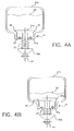
- Fig. 4A is a view of a replenishment processing solution chamber with a valve of the dispensing mechanism being in a closed position; and
- Fig. 4B is a view of the replenishment processing solution chamber of Fig. 4A showing the valve in an open position.
-
- Referring now to the drawings, wherein like reference numerals represent identical or corresponding parts throughout the several views, Figs. 1 and 2 illustrates a
processing arrangement 10 having a plurality of processing sections orprocessors 10a-10e. Each processing section orprocessor 10a-10e may be designed to hold a processing solution for processing a photosensitive material passing therethrough. In the embodiment illustrated in Figs. 1 and 2, eachindividual processing section 10a-10e can be dedicated to, for example, a developing solution; a bleaching solution; a fixing solution; a stabilizer solution or a washing solution. Figs. 1 and 2 also illustrate adryer 14 positioned at anexit 21 ofprocessing arrangement 10. Each of processing sections orprocessors narrow processing channel 15 which extends through theentire processing arrangement 10. Reference can be made to, for example, U.S. Patent Nos. 5,353,087 and 5,903, 795 for examples of representative low volume processing arrangements having a narrow processing channel. During processing, and with reference to Figs. 1 and 2, aphotosensitive material 17 can be introduced intoprocessing channel 15 atentrance 19.Photosensitive material 17 passes through each of processing sections orprocessors 10a-10e and is treated with an appropriate processing solution specific to that processing section or processor as it passes alongprocessing channel 15. After processing,photosensitive material 17 is introduced todryer 14 for drying. Each ofprocessing sections 10a-10e includes aconveying roller arrangement 25. Each ofconveying roller arrangements 25 can include a driven roller and a drive roller which is driven by way, for example, a motor and chain and belt drive assembly. Conveyingroller arrangement 25 is effective to convey photosensitive material along processingchannel 15 and throughprocessing arrangement 10.Processing arrangement 10 can be designed in a manner such that a lower conveying roller ofconveying roller arrangement 25 is at least partially immersed in the processing solution held inprocessing channel 15, (see for example, U.S. Patent Nos. 5,903,795 and 5,353,087). However, the present invention is not limited to using a partially immersed lower roller as shown. For example, solution can be fed to the tank without contacting the rollers. - A feature of the present invention relates to the replenishment system for the processing solution. More specifically, as illustrated in Figs. 1 and 2, the present invention includes a replenishment system which comprises a replenishment or dispensing chamber (27a, 27b, 27c, 27d and 27e) which holds replenishment processing solution particular to the processing section or
processor 10a-10e. For example,replenishment chamber 27a will hold developing solution for processing of photosensitive material inprocessing section 10a. Asphotosensitive material 17 is processed and passes throughprocessing channel 15, the processing solution is used up and needs to be replenished. The present invention provides for a unique replenishment system, the particulars of which are shown in Fig. 3, which replenishes processing solution based on what the photosensitive media or material extracts. - More specifically, and referring to Fig. 3, this figure illustrates one replenishing or dispensing
chambers 27a. It is recognized thatreplenishment chambers 27b-27e would be similar in structure toreplenishment chamber 27a and thus, the present description will focus onreplenishment chamber 27a as an example. As illustrated in Fig. 3, the replenishment system comprises a replenishment or dispensingchamber 27a which holds areplenishment processing solution 29 therein and a dispensing mechanism. The dispensing mechanism includes avalve 31 positioned at an opening oraperture 35 ofchamber 27a.Valve 31 includes afirst member 31a which is effective to seal or close off opening 35 in a closed position ofvalve 31.Valve 31 further includes asecond member 31b which is designed to abut against a cam in a manner which will be described later.Valve 31 also includes aspring member 33 which abuts against aframe 37 ofchamber 27a and provides a biasing force to urgevalve 31 to the closed position as illustrated in Fig. 4a.Frame 37 includesopenings 37a to permit the passage of fluid therethrough. - Referring back to Fig. 3, conveying
roller arrangement 25 is also shown. Conveyingroller arrangement 25 includes a first or upper conveyingroller 25a and a second or lower conveyingroller 25b. One of the first andsecond rollers roller 25b is a drive roller that is driven by a known motor and chain or belt drive arrangement.Roller 25b is also immersed in processing solution, while processingchannel 15 extends betweenrollers - As illustrated in Fig. 3,
roller 25b includes ashaft 39 that is connected toroller 25b and extends fromroller 25b to an eccentric cam member orroller 41. Thus,eccentric cam roller 41 rotates in coordination with a rotation ofroller 25b. As illustrated in Figs. 3, 4A and 4B,eccentric cam roller 41 has an outer surface which abuts against an outer surface ofsecond member 31b ofvalve 31. Therefore, based on the rotation ofroller 25b,eccentric cam roller 41 will rotate accordingly. Of course, it is recognized that the present invention is not limited to an eccentricallymounted cam roller 41 as illustrated. As an alternative,cam roller 41 could be mounted at its rotational center and have an outer surface which varies by an amount necessary to movevalve 31 the appropriate amount. - Operation of the replenishment system as illustrated in the Figs. 3, 4A and 4B will now be described using
processing section 10a andchamber 27a as examples. Asphotosensitive material 17 is introduced intonarrow processing channel 15, it will be conveyed alongprocessing channel 15. As the photosensitive material passes betweenrollers roller 25b will be rotated to convey the photosensitive material therethrough. The rotation ofroller 25b in accordance with the passage of photosensitive material therethrough causes a corresponding rotation ofeccentric cam roller 41. Based on this,cam roller 41 moves from the position shown in Fig. 4A in whichvalve 31 is in a closed position. More specifically, in the position shown in Fig. 4A,eccentric cam roller 41 andvalve 31 are in a closed position in whichsecond member 31 a abuts against sealingsurface 45 to seal aperture or opening 35 ofprocessing chamber 27a. In the closed position of Fig. 4A,spring member 33 which extends betweenframe 37 andsecond member 31b, provides for a biasing force for maintainingvalve 31 in the closed position and more particularly,second member 31a abutted against sealingsurfaces 45 ofchamber 27a. Ascam roller 41 is rotated in accordance with the corresponding rotation ofroller 25b, i.e. when photosensitive material is passing betweenrollers cam roller 41 will be rotated from the closed position illustrated in Fig. 4A to the open position illustrated in Fig. 4B. - More specifically, as
cam roller 41 rotates, an outer surface ofcam roller 41 abuts against an outer surface ofsecond member 31b ofvalve 31 to urgevalve member 31 against the biasing force ofspring member 33. This causes the movement ofvalve 31 to the open position so as to separatefirst member 31a from sealingsurfaces 45 and thus, open aperture or opening 35 ofchamber 27a. In the open position shown in Fig. 4B, the replenishment solution inchamber 27a is dispensed via asolution path 38 to the processor orprocessing channel 15 in direct relationship with the amount of photosensitive media that passes throughprocessing channel 15. Thus, if the photosensitive media is a longer piece of media, more replenishment solution will be dispensed to the processor orprocessing channel 15, and if a shorter piece of media passes betweenrollers processing channel 15. Therefore, the replenishment processing solution is metered or dispensed in correlation with the amount of processing solution extracted by the media. Further, the amount of replenishment solution dispensed is related or tied to the driving of the media throughprocessing channel 15. More specifically, the rotation ofcam roller 41 is tied to the rotation ofroller 25b which is related to the passage of photosensitive media betweenrollers - Accordingly, when
valve 31 is in a closed position as illustrated in Fig. 4A, photosensitive media is not in the vicinity ofrollers rollers roller arrangement 25 or has already passed conveyingroller arrangement 25. Whenvalve 31 is in the opened position as illustrated in Fig. 4B for dispensing processing solution, the photosensitive media is in the vicinity of conveyingroller arrangement 25. More specifically, the photosensitive media is passing between therollers roller 25b being rotated and causing a corresponding rotation ofeccentric cam roller 41. - In a preferred method of operation the rotation of
roller 25b which causes a rotation ofcam roller 41 is controlled such thatvalve 31 is in the opened position only when media is being transported and in the closed position when media exits the processor. - Thus, the present invention provides for a processor or processing arrangement in which a dispensing mechanism is provided that meters an amount of replenishment solution in direct relationship to the amount of media that passes through the processor. The system of the present invention is also effective to meter an amount of replenishment processing solution at a sufficient strength to provide an appropriate amount of active chemistry for processing of the photosensitive media in the processing channel. The dispensing mechanism includes a cam roller that is operationally associated with a conveying or drive roller. The cam roller is rotated in association with the conveying or drive roller and engages a valve on a dispensing or replenishment chamber. When the valve is pushed up or moved to an opened position, an amount of processing solution is metered out or dispensed in response to the amount that the drive or conveying roller is rotated. With this arrangement, a longer piece of media will get more replenishment. The photosensitive media used in the present invention is preferably in the form of discrete pieces of media.
- As indicated above, it is recognized that
replenishment chambers 27b-27e, as well as the valve, cam rollers and conveying or drive rollers associated withreplenishment chambers 27b-27e are similar in structure to the describedreplenishment chamber 27a and operate in the same manner. Therefore, as photosensitive material conveyed throughprocessing channel 15 passes throughprocessing sections 10b-10e, replenishment solution is dispensed from each ofreplenishment chambers 27b-27e in the same manner as described with reference toreplenishment chamber 27a.
Claims (10)
- A processor for processing photosensitive media, the processor comprising:a processing channel (15) through which a photosensitive media (17) is passed, said processing channel containing processing solution for application to the photosensitive media passing therethrough; anda replenishment system adapted to replenish the processing solution in said processing channel, said replenishment system comprising a chamber (27a, 27b, 27c, 27d, 27e) for holding a processing solution therein and a dispensing mechanism which dispenses the processing solution from said chamber in direct relationship with an amount of the photosensitive media passing through said processing channel.
- A processor according to claim 1, wherein said photosensitive media comprises a plurality of discreet pieces of media.
- A processor according to claim 1, wherein the dispensing mechanism comprises:a valve (31) having an open and a closed position for opening and closing an aperture (35) of said chamber, such that in said opened position of said valve, processing solution in said chamber is dispensed from said chamber to said processing channel, the opening and closing of said valve being in direct relation to the amount of said photosensitive media passing through said channel.
- A processor according to claim 3, further comprising:wherein:a conveying roller adapted to convey photosensitive material along the processing channel; anda cam roller operationally associated with said conveying roller;in response to a rotation of said conveying roller said cam roller is rotated to move said valve to said open position and maintain said valve in said open position while said photosensitive media is in a vicinity of said conveying roller, andin response to a further rotation of said conveying roller said cam roller is further rotated to permit a movement of said valve to said closed position when said photosensitive media is not in a vicinity of said conveying roller.
- A processor according to claim 3, further comprising:a cam roller adapted to maintain said valve in either the open position or the closed position based on the passage of the photosensitive media through the processing channel.
- A method of processing photosensitive media, the method comprising:passing a photosensitive media to be processed through a processing channel which contains photosensitive solution for application to the photosensitive media; andreplenishing the processing solution in the processing channel by dispensing processing solution into the processing channel in direct relationship with an amount of the photosensitive media passing through the processing channel.
- A method according to claim 6, wherein said replenishing step comprises dispensing processing solution of a sufficient strength to provide an appropriate amount of active chemistry for processing to said photosensitive media in said processing channel.
- A method according to claim 6, wherein said processing solution to be dispensed is held in a chamber having a valve which is movable between open and closed positions for respectively opening and closing an opening in said valve, such that said replenishing step comprises moving said valve from the closed position to the open position to dispense processing solution from said chamber to said processing channel via said opening, said movement of said valve being based on a passage of photosensitive material through said processing channel.
- A replenishment system for a photographic processor, the replenishment system comprising:a chamber for holding a processing solution therein and a dispensing mechanism which dispenses the processing solution from said chamber in direct relationship with an amount of photosensitive media being processed in a photographic processor.
- A replenishment system for a photographic processor, the replenishment system comprising:a chamber which holds a processing solution therein; anda dispensing mechanism which dispenses the processing solution from the chamber, said dispensing mechanism comprising a valve having a surface which engages a cam roller, said cam roller being operationally connected to a conveying roller of a photographic processor so as to rotate together with the conveying roller, such that a rotation of said cam roller by way of a rotation of said conveying roller causes a movement of the valve between a closed position and an open position, wherein in said open position of said valve, processing solution is dispensed from said chamber to the photographic processor.
Applications Claiming Priority (2)
| Application Number | Priority Date | Filing Date | Title |
|---|---|---|---|
| US745720 | 2000-12-21 | ||
| US09/745,720 US6409399B1 (en) | 2000-12-21 | 2000-12-21 | Photographic processor having a roller cam replenishment system |
Publications (1)
| Publication Number | Publication Date |
|---|---|
| EP1217443A1 true EP1217443A1 (en) | 2002-06-26 |
Family
ID=24997957
Family Applications (1)
| Application Number | Title | Priority Date | Filing Date |
|---|---|---|---|
| EP01204823A Withdrawn EP1217443A1 (en) | 2000-12-21 | 2001-12-10 | Photographic processor |
Country Status (3)
| Country | Link |
|---|---|
| US (1) | US6409399B1 (en) |
| EP (1) | EP1217443A1 (en) |
| JP (1) | JP2002229171A (en) |
Families Citing this family (1)
| Publication number | Priority date | Publication date | Assignee | Title |
|---|---|---|---|---|
| JP5138535B2 (en) * | 2008-10-14 | 2013-02-06 | 三菱重工業株式会社 | Booster / decelerator |
Citations (4)
| Publication number | Priority date | Publication date | Assignee | Title |
|---|---|---|---|---|
| US4134663A (en) * | 1975-12-19 | 1979-01-16 | Agfa-Gevaert Ag | Method and apparatus for feeding replenishment chemicals in film processors |
| EP0491049A1 (en) * | 1990-07-09 | 1992-06-24 | Fuji Photo Film Co., Ltd. | Device for processing silver halide photosensitive material |
| EP0590619A1 (en) * | 1992-10-02 | 1994-04-06 | Eastman Kodak Company | Apparatus for processing photosensitive material |
| US5353087A (en) * | 1993-05-03 | 1994-10-04 | Eastman Kodak Company | Automatic replenishment, calibration and metering system for an automatic tray processor |
Family Cites Families (9)
| Publication number | Priority date | Publication date | Assignee | Title |
|---|---|---|---|---|
| FR1595699A (en) * | 1967-11-17 | 1970-06-15 | ||
| JPS5086345A (en) | 1973-11-28 | 1975-07-11 | ||
| DE3788365T2 (en) | 1986-04-09 | 1994-03-24 | Fuji Photo Film Co Ltd | Method for supplying regeneration liquid in an automatic developing machine. |
| US4987438A (en) * | 1988-06-27 | 1991-01-22 | Konica Corporation | Apparatus for processing light-sensitive material |
| US4888607A (en) * | 1988-09-15 | 1989-12-19 | Alto Technology | Photograph processing method and apparatus |
| US5025279A (en) | 1990-03-21 | 1991-06-18 | Eastman Kodak Company | Process for replenishing solutions in a film processor |
| DE69129095T2 (en) * | 1990-10-23 | 1998-10-15 | Dainippon Screen Mfg | Method and device for treating photosensitive materials |
| US5903795A (en) | 1997-05-23 | 1999-05-11 | Eastman Kodak Company | Photographic processor |
| JP3672284B2 (en) * | 1997-09-08 | 2005-07-20 | コニカミノルタホールディングス株式会社 | Automatic processing machine for silver halide photographic materials |
-
2000
- 2000-12-21 US US09/745,720 patent/US6409399B1/en not_active Expired - Fee Related
-
2001
- 2001-12-10 EP EP01204823A patent/EP1217443A1/en not_active Withdrawn
- 2001-12-19 JP JP2001386092A patent/JP2002229171A/en active Pending
Patent Citations (4)
| Publication number | Priority date | Publication date | Assignee | Title |
|---|---|---|---|---|
| US4134663A (en) * | 1975-12-19 | 1979-01-16 | Agfa-Gevaert Ag | Method and apparatus for feeding replenishment chemicals in film processors |
| EP0491049A1 (en) * | 1990-07-09 | 1992-06-24 | Fuji Photo Film Co., Ltd. | Device for processing silver halide photosensitive material |
| EP0590619A1 (en) * | 1992-10-02 | 1994-04-06 | Eastman Kodak Company | Apparatus for processing photosensitive material |
| US5353087A (en) * | 1993-05-03 | 1994-10-04 | Eastman Kodak Company | Automatic replenishment, calibration and metering system for an automatic tray processor |
Also Published As
| Publication number | Publication date |
|---|---|
| US6409399B1 (en) | 2002-06-25 |
| US20020081116A1 (en) | 2002-06-27 |
| JP2002229171A (en) | 2002-08-14 |
Similar Documents
| Publication | Publication Date | Title |
|---|---|---|
| EP0559027B1 (en) | A driving mechanism for a photographic processing apparatus | |
| EP1217443A1 (en) | Photographic processor | |
| US5353087A (en) | Automatic replenishment, calibration and metering system for an automatic tray processor | |
| US5353088A (en) | Automatic tray processor | |
| JP3252242B2 (en) | Solid processing agent replenisher for photosensitive material processing | |
| US5353086A (en) | Textured surface with canted channels for an automatic tray processor | |
| US5960227A (en) | Photosensitive material processing apparatus | |
| EP0623843B1 (en) | Automatic replenishment,calibration and metering system for automatic processors | |
| JPH11125892A (en) | Photosensitive material processing equipment | |
| JPH02205846A (en) | Processing device for photosensitive material | |
| JP2002229172A (en) | Processing of photographic materials | |
| US6203219B1 (en) | Photosensitive material processing apparatus | |
| JPH0315060A (en) | Small-sized automatic developing machine for photographic sensitive material | |
| JP2696762B2 (en) | Photosensitive material processing equipment | |
| US5585880A (en) | Solid processing agent replenishing apparatus for processing photosensitive material | |
| US6361226B1 (en) | Belt drive rack and tank photographic processing apparatus | |
| JP2670932B2 (en) | Photosensitive material processing equipment | |
| JP3617721B2 (en) | Photosensitive material processing equipment | |
| JPH02161431A (en) | Photosensitive material processing device | |
| JPH09292688A (en) | Photosensitive material processing equipment | |
| JP3283096B2 (en) | Photosensitive material processing equipment | |
| JPH09292693A (en) | Photosensitive material processing equipment | |
| JPH02204741A (en) | Device for processing photosensitive material | |
| EP0669554A1 (en) | Solid processing agent replenishing device for use in a photosensitive material processing apparatus | |
| JPH03100650A (en) | Processing tank unit |
Legal Events
| Date | Code | Title | Description |
|---|---|---|---|
| PUAI | Public reference made under article 153(3) epc to a published international application that has entered the european phase |
Free format text: ORIGINAL CODE: 0009012 |
|
| AK | Designated contracting states |
Kind code of ref document: A1 Designated state(s): AT BE CH CY DE DK ES FI FR GB GR IE IT LI LU MC NL PT SE TR |
|
| AX | Request for extension of the european patent |
Free format text: AL;LT;LV;MK;RO;SI |
|
| 17P | Request for examination filed |
Effective date: 20021130 |
|
| AKX | Designation fees paid |
Designated state(s): CH DE FR GB IT LI |
|
| 17Q | First examination report despatched |
Effective date: 20030206 |
|
| GRAP | Despatch of communication of intention to grant a patent |
Free format text: ORIGINAL CODE: EPIDOSNIGR1 |
|
| STAA | Information on the status of an ep patent application or granted ep patent |
Free format text: STATUS: THE APPLICATION IS DEEMED TO BE WITHDRAWN |
|
| 18D | Application deemed to be withdrawn |
Effective date: 20040220 |