EP1217380A1 - Anémometre pour hélicoptère - Google Patents
Anémometre pour hélicoptère Download PDFInfo
- Publication number
- EP1217380A1 EP1217380A1 EP01403199A EP01403199A EP1217380A1 EP 1217380 A1 EP1217380 A1 EP 1217380A1 EP 01403199 A EP01403199 A EP 01403199A EP 01403199 A EP01403199 A EP 01403199A EP 1217380 A1 EP1217380 A1 EP 1217380A1
- Authority
- EP
- European Patent Office
- Prior art keywords
- pressure
- speed
- probe
- phase
- samples
- Prior art date
- Legal status (The legal status is an assumption and is not a legal conclusion. Google has not performed a legal analysis and makes no representation as to the accuracy of the status listed.)
- Granted
Links
- 239000000523 sample Substances 0.000 claims abstract description 84
- 238000005259 measurement Methods 0.000 claims abstract description 25
- 238000009530 blood pressure measurement Methods 0.000 claims abstract description 15
- 230000003068 static effect Effects 0.000 claims description 9
- 238000000034 method Methods 0.000 claims description 8
- 102100024853 Carnitine O-palmitoyltransferase 2, mitochondrial Human genes 0.000 claims description 6
- 101000909313 Homo sapiens Carnitine O-palmitoyltransferase 2, mitochondrial Proteins 0.000 claims description 6
- 101000859570 Homo sapiens Carnitine O-palmitoyltransferase 1, liver isoform Proteins 0.000 claims description 5
- 101000989606 Homo sapiens Cholinephosphotransferase 1 Proteins 0.000 claims description 5
- 230000000875 corresponding effect Effects 0.000 abstract description 17
- 230000001360 synchronised effect Effects 0.000 abstract description 3
- 230000002596 correlated effect Effects 0.000 abstract description 2
- 239000003570 air Substances 0.000 description 37
- 230000015654 memory Effects 0.000 description 10
- 230000006870 function Effects 0.000 description 7
- 102100039164 Acetyl-CoA carboxylase 1 Human genes 0.000 description 2
- 101710190443 Acetyl-CoA carboxylase 1 Proteins 0.000 description 2
- 102100021641 Acetyl-CoA carboxylase 2 Human genes 0.000 description 2
- 101000677540 Homo sapiens Acetyl-CoA carboxylase 2 Proteins 0.000 description 2
- 101000894929 Homo sapiens Bcl-2-related protein A1 Proteins 0.000 description 2
- 239000012080 ambient air Substances 0.000 description 2
- 241000940835 Pales Species 0.000 description 1
- 206010033546 Pallor Diseases 0.000 description 1
- 230000001133 acceleration Effects 0.000 description 1
- 238000009529 body temperature measurement Methods 0.000 description 1
- 239000000872 buffer Substances 0.000 description 1
- 230000007423 decrease Effects 0.000 description 1
- 238000010586 diagram Methods 0.000 description 1
- 238000006073 displacement reaction Methods 0.000 description 1
- 230000000694 effects Effects 0.000 description 1
- 238000002474 experimental method Methods 0.000 description 1
- 238000000691 measurement method Methods 0.000 description 1
- 239000012528 membrane Substances 0.000 description 1
- 230000010355 oscillation Effects 0.000 description 1
- 230000010363 phase shift Effects 0.000 description 1
- 230000017105 transposition Effects 0.000 description 1
- 230000001960 triggered effect Effects 0.000 description 1
Images


Classifications
-
- G—PHYSICS
- G01—MEASURING; TESTING
- G01P—MEASURING LINEAR OR ANGULAR SPEED, ACCELERATION, DECELERATION, OR SHOCK; INDICATING PRESENCE, ABSENCE, OR DIRECTION, OF MOVEMENT
- G01P5/00—Measuring speed of fluids, e.g. of air stream; Measuring speed of bodies relative to fluids, e.g. of ship, of aircraft
-
- G—PHYSICS
- G01—MEASURING; TESTING
- G01P—MEASURING LINEAR OR ANGULAR SPEED, ACCELERATION, DECELERATION, OR SHOCK; INDICATING PRESENCE, ABSENCE, OR DIRECTION, OF MOVEMENT
- G01P13/00—Indicating or recording presence, absence, or direction, of movement
- G01P13/02—Indicating direction only, e.g. by weather vane
-
- G—PHYSICS
- G01—MEASURING; TESTING
- G01P—MEASURING LINEAR OR ANGULAR SPEED, ACCELERATION, DECELERATION, OR SHOCK; INDICATING PRESENCE, ABSENCE, OR DIRECTION, OF MOVEMENT
- G01P5/00—Measuring speed of fluids, e.g. of air stream; Measuring speed of bodies relative to fluids, e.g. of ship, of aircraft
- G01P5/14—Measuring speed of fluids, e.g. of air stream; Measuring speed of bodies relative to fluids, e.g. of ship, of aircraft by measuring differences of pressure in the fluid
Definitions
- the invention relates to the measurement of the speed of a helicopter by compared to air.
- the measurement of the speed of aircraft is generally made from anemobarometric units which calculate the speed of the aircraft relative to the ambient air from static pressure measurements, total pressure and temperature: static pressure and temperature constant static, the total pressure measured increases and decreases as the speed according to a known law.
- the amplitude of the instantaneous speed of the probe relative to air varies sinusoidally around an average value which represents the speed of rotation of the blades; the amplitude of the sinusoid represents the forward speed of the helicopter relative to the air; and the phase represents the direction of advance relative to a reference direction of the helicopter: the maximum of the sinusoid of speed occurs at the moment when the probe is turned towards the direction of advance of the helicopter, while the minimum occurs when the probe is turned in the opposite direction.
- the total pressure measured by the probe does not vary linearly with speed. But it follows a known law of variation, classic in anémobarométrie. When the speed varies sinusoidally, the pressure follows then a curve of variation which one can qualify as deformed sinusoid.
- the object of the invention is to propose a particularly simple to determine the amplitude and direction of the velocity vector of a helicopter.
- the invention further provides a speed measurement system comprising the means necessary for the implementation of the process which comes to be described in outline.
- the pressure probe can be a probe providing pulses whose periodicity is a function of the pressure, and it is then expected to preferably a circuit for determining the value of this periodicity, this circuit providing pressure measurement sample values represented by the value of the specified period.
- This circuit can be a simple pulse counter circuit at much higher frequency than that of the pulses supplied by the probe, this circuit counting the number high frequency pulses emitted during one or more periods of pulses from the probe.
- the accumulators which calculate the sums S1 and S2 can then simply receive during this time the counting frequency of this counter, and count or count the pulses received at frequency high depending on the state of the first and second binary signals.
- the accumulators are reset to zero after a full rotation of the blade, and it is then that the arctg calculation (S2 / S1) is carried out.
- the probe can be located at the end of the blade or in a part intermediate. At the end of the blade, it must then be more resistant to strong accelerations, and in particular centrifugal force.
- the probe is preferably turned towards the front of the blade, in the direction of rotation of the blade (perpendicular to the length of the blade by therefore) to measure the maximum air pressure due to the speed of rotation of the blade rather than the depression at the rear of the blade.
- the meaning of rotation is clockwise in the figures.
- the probe should also be placed in a plane corresponding to the reference base of the helicopter, so that the calculated helicopter speed is referenced in relation to this plate.
- the blade 12 is shown in a position of reference used in the speed calculation.
- a reference the position of the blade 12 in the longitudinal axis of the structure of the helicopter and backwards, the speed of the helicopter by relative to air being defined with respect to this longitudinal axis.
- V air represents the speed of the helicopter relative to air. It makes an angle ⁇ with the longitudinal reference axis of the helicopter.
- the determination of the speed comprises the determination of the angle ⁇ and of the amplitude V air .
- the instantaneous linear speed of the probe relative to the helicopter is a vector Vi of amplitude L ⁇ , if L is the distance between the probe and the axis of the rotor, and of direction ⁇ t + ⁇ / 2.
- the speed of the probe relative to the air knowing that the helicopter advances with the speed V air in the direction defined by the angle ⁇ , is a vector V'i which is the vector combination of Vi and V air .
- This combined vector V'i can be broken down into two components, one in the longitudinal direction of the blade, without effect on the pressure probe, and the other, designated by V "i in the direction perpendicular to the blade, direction where the probe is most sensitive to pressure.
- This speed component therefore varies according to a sinusoidal curve oscillating with an amplitude of + V air to -V air around an average value ⁇ L and with a phase (determined relative to the reference position of the blade) which is the angle ⁇ representing the direction of advance of the helicopter.
- the speed measurement would simply consist in locating the amplitude of the oscillation and its phase in order to know the speed vector V air in amplitude and direction.
- the probe itself has characteristics that are not necessarily linear.
- a capacitive type probe with a resonant membrane, producing an output signal in the form of a resonant frequency value, provides pressure measurement samples which do not vary linearly as a function of pressure.
- P 0 depends in practice on the temperature of the sensor.
- the pressure measured by the probe varies under these conditions according to a deformed sinusoid represented in FIG. 4, the maxima and minima are located in the same places as those of the speed sine wave, but whose phase ⁇ is difficult to determine from the simple observation of the curve, and whose mean value does not correspond elsewhere not at the average speed value ⁇ L of the probe.
- the frequency provided by the probe varies in the same way, with another deformation of sinusoid, but with these same peculiarities due to the monotony of the frequency / pressure function.
- a Fourier transform treatment on the pressure samples obtained during a complete rotation also makes it possible to go back to the phase and to the air speed V but also requires powerful calculation means.
- the present invention provides a much simpler means which is based on the fact that although the sinusoid is deformed, it is strongly correlated with the shape of the speed sinusoid which has same period and same phase, the maxima and minima of the deformed sinusoid coinciding with those of the speed sine wave (or possibly reversed); we should therefore be able, by a simple correlation, to find the phase of the velocity sine corresponding to the pressure sine or the sinusoid of any signal samples.
- the probe therefore supplies N samples at each revolution of the rotor.
- pressure measurement periodicals whose values are stored in memory and each associated with the value of the measurement instant (this storage is useful for amplitude measurement but not for phase measurement) ; this instant is expressed for example in the form of a phase angle 2k ⁇ / N where k represents the sample number from 1 to N. For example, it is simply the sample number k which serves as an address in a memory where we store the sample value at this address.
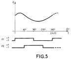
- the first waveform has for example the value +1 while the angle of rotation ⁇ t is greater than or equal to 0 ° and less than 180 °, then the value -1 as long as the angle is greater than or equal to 180 ° and less than 360 °.
- the second waveform then takes the value -1 from 0 ° to 90 ° and 270 ° to 360 ° and the +1 value from 90 ° to 270 °.
- Sum S1 sum of the samples obtained for a first state of the first waveform (+1 in principle), minus the sum of samples obtained for the second state of the first waveform
- Sum S2 sum of the samples obtained for a first state of the second waveform (+1 in principle), minus the sum of samples obtained for the second state of the second waveform.
- FIG. 5 represents the square waveforms F1 and F2, calibrated in phase on the rotation of the rotor, opposite the pressure value curve transmitted by the probe.
- the angle ⁇ is equal to arctg (S2 / S1) if the slots F1 and F2 are referenced as shown above, but could be equal to-arctg (S2 / S1) with an F2 waveform phase shifted by -90 ° rather than + 90 ° compared to F1.
- phase values given above for binary signals F1 and F2 relate to the case where the pressure samples vary as the probe speed. If they vary in the opposite direction, we will modify them, by example by reversing the phase of F1 which would then have the value -1 from 0 to 180 °.
- V air (Vi "max-Vi" min) / 2
- the speed calculation conventionally involves static pressure and air temperature, which must be known elsewhere.
- the invention has been illustrated in the case of a pressure probe providing pulses whose frequency (therefore period) varies in pressure function.
- the pulse frequency of the probe is not very high (a few tens of kilohertz)
- This counting is done with a counting frequency fixed much greater than the frequency of the pulses supplied by the probe. We can count the period separating two successive pulses, or better the duration of several successive pulses from the probe.
- a general HG clock synchronized with the rotation of the rotor which general is regular, defines the N instants of measurement, for example under pulse form at frequency N ⁇ . It also defines the binary signals F1 and F2 used for correlation.
- f a frequency directly representing this period, so the reverse of the frequency, therefore a value representing the pressure.
- counting is stopped after several pulses (always the same number of course, defined for example by a counter CPT2) which gives a account representing a sum of several periods, representing also the pressure.
- the counter value at the end of the count is stored in a MEM memory, at an address k corresponding to the measurement instant. This address is incremented with each new sample by the general clock HG which defines the instants of measurement. A stored value can also be read later by applying a reading address corresponding to a determined measurement instant.
- the memory is completely filled at each revolution of the rotor, replacing the old values. Memories buffers for filling the memory, or operating with two memories working alternately in reading and writing at each turn is of course provided if the time required for the speed calculation requires keep the contents of a lap memory before filling it for the lap next.
- Binary slots F1 and F2 each control an accumulator respective ACC1, ACC2.
- the accumulators are initialized to zero when rotor passage through its reference position. They add up the samples as they arrive, positive or negative depending on the condition of binary signals F1, F2 which control them. So they calculate the sums S1 and S2 which are available in the accumulators at the end of a round for be used in an arctg calculation circuit (S2 / S1).
- Accumulators could be adders / subtractors who would receive the samples from the CPT1 counter as they arrive and add or subtract them depending on the state of F1 and F2. But, as shown in Figure 5, it is simpler to provide that the ACC1 and ACC2 accumulators are simple up / down counters which directly receive the pulses from counting of counter CPT1 (in principle at frequency f or submultiple of f) as long as the counter counts and which accumulate them algebraically in counting or counting these pulses according to the state of F1 and F2.
- the accumulators At the end of a rotor revolution, the accumulators contain the sums S1 and S2 and transfer them to an arctg calculation circuit (S2 / S1) before being reset for a new lap.
- the circuit for calculating ⁇ arctg (S2 / S1) directly supplies the direction of the helicopter's speed vector. In addition, it provides information to a calculation circuit of ⁇ + 90 ° and ⁇ + 270 °.
- the latter supplies the memory MEM, in reading, with the addresses k 0 + N / 4 and k 0 + 3N / 4 corresponding to these phases.
- the values of stored samples are extracted from the memory and transmitted to a pressure calculation circuit Pmin and Pmax from the values of stored samples.
- the Pmin and Pmax calculation circuit uses the data pressure probe characteristics to deduce from numbers representing the pulse periods from the value probe digital pressure. This circuit can involve a measurement of probe temperature, and in this case temperature information the probe is supplied by it (case of the pressure probes associated with a local temperature sensor).
- Vmin and Vmax determines Vmin and Vmax according to the formulas anemobarometrics indicated above. This calculation is done in principle intervene a static pressure measurement and a temperature value of air (static temperature or total temperature according to the definitions in use in anemobarometry). Static pressure and temperature, obtained elsewhere, are therefore transmitted to this circuit.
- the circuit for calculating Vmin and Vmax provides the value V air which is half the difference between Vmin and Vmax.
Landscapes
- Physics & Mathematics (AREA)
- General Physics & Mathematics (AREA)
- Engineering & Computer Science (AREA)
- Aviation & Aerospace Engineering (AREA)
- Measuring Fluid Pressure (AREA)
Abstract
Description
- obtenir N échantillons de mesure de pression Pi répartis sur l'ensemble d'une rotation complète de la pale,
- produire un premier signal binaire changeant d'état au passage
de la pale par des orientations remarquables situées à 0° et
180° d'une orientation de référence de la pale, et un deuxième
signal binaire en quadrature de phase avec le premier et
changeant d'état à 90° et 270°, et effectuer les sommes
suivantes S1 et S2 pendant une rotation complète :
- S1 : somme des échantillons obtenus pendant un premier état du premier signal binaire diminuée de la somme des échantillons obtenus pendant le deuxième état du premier signal ;
- S2 : somme des échantillons obtenus pendant un premier état du deuxième signal binaire diminuée de la somme des échantillons obtenus pendant le deuxième état du deuxième signal binaire,
- calculer une valeur numérique représentant arctg(S2/S1), le résultat de ce calcul déterminant une phase remarquable correspondant à une direction de la vitesse cherchée.
- une sonde de pression placée sur une pale du rotor de l'hélicoptère, cette sonde foumissant des signaux représentant la pression mesurée par la sonde,
- des moyens pour obtenir des échantillons de mesure de pression répartis au cours d'une rotation complète de la pale,
- des moyens pour produire un premier signal binaire changeant d'état au passage de la pale par des orientations remarquables situées à 0° et 180° d'une orientation de référence de la pale, et un deuxième signal binaire en quadrature de phase avec le premier et changeant d'état à 90° et 270°,
- un premier accumulateur numérique pour calculer la somme S1 des échantillons obtenus pendant un premier état du premier signal binaire diminuée de la somme des échantillons obtenus pendant le deuxième état du premier signal ;
- un deuxième accumulateur numérique pour calculer la somme S2 des échantillons obtenus pendant un premier état du deuxième signal binaire diminuée de la somme des échantillons obtenus pendant le deuxième état du deuxième signal binaire,
- des moyens pour calculer une valeur numérique représentant arctg(S2/S1), le résultat de ce calcul déterminant une phase remarquable correspondant à une direction de la vitesse cherchée.
- des moyens pour stocker les échantillons de pression en relation avec les instants de mesure correspondants,
- des moyens pour additionner une valeur π/2 et une valeur 3π/2 à la phase (modulo 2π), pour obtenir deux autres phases remarquables Φmax et Φmin représentant les instants de mesure théorique du maximum et du minimum de la courbe de valeurs de pression au cours de la rotation,
- des moyens pour rechercher dans les échantillons stockés des valeurs d'échantillons de pression Pmax et Pmin correspondant à ces instants, des moyens de calcul de la vitesse instantanée Vmax et Vmin correspondant à ces valeurs de pression Pmax et Pmin, et des moyens pour déterminer l'amplitude Vair de la vitesse de l'hélicoptère par rapport à l'air à partir de Vmax et Vmin.
- la figure 1 représente une hélicoptère dont une des pales de sustentation porte une sonde de pression, la pale étant dans une position de référence par rapport à la structure de l'hélicoptère ;
- la figure 2 représente l'hélicoptère avec la pale dans une position quelconque au cours de sa rotation ;
- la figure 3 représente la sinusoïde de vitesse de la sonde ;
- la figure 4 représente la sinusoïde déformée de pression mesurée par la sonde ;
- la figure 5 représente le principe de corrélation permettant de déterminer la phase de la sinusoïde déformée ;
- la figure 6 représente un schéma bloc d'un circuit de mise en oeuvre préférentiel du procédé de mesure de vitesse selon l'invention.
Claims (7)
- Procédé de détermination de vitesse d'hélicoptère utilisant une sonde de pression (14) montée sur une pale (12) du rotor, ce procédé consistant à :obtenir N échantillons de mesure de pression Pi répartis sur l'ensemble d'une rotation complète de la pale,produire un premier signal binaire (F1) changeant d'état au passage de la pale par des orientations remarquables situées à 0° et 180° d'une orientation de référence de la pale, et un deuxième signal binaire (F2) en quadrature de phase avec le premier et changeant d'état à 90° et 270°, et effectuer les sommes suivantes S1 et S2 pendant une rotation complète :S1 : somme des échantillons obtenus pendant un premier état du premier signal binaire diminuée de la somme des échantillons obtenus pendant le deuxième état du premier signal ;S2 : somme des échantillons obtenus pendant un premier état du deuxième signal binaire diminuée de la somme des échantillons obtenus pendant le deuxième état du deuxième signal binaire,calculer une valeur numérique représentant arctg(S2/S1), le résultat de ce calcul déterminant une phase remarquable correspondant à une direction de la vitesse cherchée.
- Procédé selon la revendication 1, caractérisé en ce que, pour déterminer ensuite l'amplitude de la vitesse, on prévoit de stocker les N échantillons de pression utilisés au cours de la détermination de la phase remarquable ainsi que les instants de mesure correspondants; on additionne une valeur π/2 et une valeur 3π/2 à la phase (modulo 2π), pour obtenir deux autres phases remarquables Φmax et Φmin représentant les instants de mesure théoriques du maximum et du minimum de la courbe de valeurs de pression mesurées au cours de la rotation, on recherche dans les échantillons stockés les valeurs d'échantillons de pression Pmax et Pmin correspondant à ces instants, et enfin on calcule la vitesse instantanée Vmax et Vmin à partir de ces valeurs de pression, en fonction d'une relation vitesse/pression, et on détermine l'amplitude de la vitesse de l'hélicoptère à partir de Vmax et Vmin.
- Procédé selon la revendication 2, caractérisé en ce que la relation vitesse/pression est la suivante :Pt = Ps(1+0,2M2)7/2 où Pt est la pression totale mesurée par la sonde, Ps est la pression statique atmosphérique, M est la vitesse exprimée en nombre de Mach.
- Système de mesure de vitesse d'hélicoptère comprenant une sonde de pression (14) placée sur une pale (12) du rotor de l'hélicoptère, cette sonde fournissant des signaux représentant la pression (Pi) mesurée par la sonde, et des moyens pour obtenir des échantillons de mesure de pression répartis au cours d'une rotation complète de la pale, caractérisé en ce qu'il comprend en outre :des moyens (HG) pour produire un premier signal binaire (S1) changeant d'état au passage de la pale par des orientations remarquables situées à 0° et 180° d'une orientation de référence de la pale, et un deuxième signal binaire (F2) en quadrature de phase avec le premier et changeant d'état à 90° et 270°,un premier accumulateur numérique (ACC1) contrôlé par le premier signal binaire pour calculer la somme S1 des échantillons obtenus pendant un premier état du premier signal binaire diminuée de la somme des échantillons obtenus pendant le deuxième état du premier signal ;un deuxième accumulateur numérique (ACC2) contrôlé par le deuxième signal binaire pour calculer la somme S2 des échantillons obtenus pendant un premier état du deuxième signal binaire diminuée de la somme des échantillons obtenus pendant le deuxième état du deuxième signal binaire,des moyens pour calculer une valeur numérique représentant arctg(S2/S1), le résultat de ce calcul déterminant une phase remarquable correspondant à une direction de la vitesse cherchée.
- Système selon la revendication 4, caractérisé en ce qu'il comprend également, pour la détermination de l'amplitude de la vitesse :des moyens (MEM) pour stocker les échantillons de pression en relation avec les instants de mesure correspondants,des moyens pour additionner une valeur π/2 et une valeur 3π/2 à la phase (modulo 2π), pour obtenir deux autres phases remarquables Φmax et Φmin représentant les instants de mesure théoriques du maximum et du minimum de la courbe de valeurs de pression au cours de la rotation,des moyens pour rechercher dans les échantillons stockés des valeurs d'échantillons de pression Pmax et Pmin correspondant à ces instants, des moyens de calcul de la vitesse instantanée Vmax et Vmin correspondant à ces valeurs de pression Pmax et Pmin, et des moyens pour déterminer l'amplitude Vair de la vitesse de l'hélicoptère par rapport à l'air à partir de Vmax et Vmin.
- Système selon l'une des revendications 4 et 5, caractérisé en ce que la sonde de pression est une sonde fournissant des impulsions dont la périodicité est fonction de la pression, et en ce qu'il est prévu un circuit (CPT1) de comptage d'impulsions à fréquence beaucoup plus élevée que celle des impulsions fournies par la sonde, ce circuit comptant le nombre d'impulsions de fréquence élevée émises pendant une ou plusieurs périodes d'impulsions issues de la sonde, et le contenu du compteur représentant une valeur d'échantillon de pression.
- Système selon la revendication 6, caractérisé en ce que les accumulateurs (ACC1, ACC2) sont des compteurs/décompteurs qui reçoivent les impulsions d'incrémentation du circuit de comptage d'impulsions (CPT1) et qui s'incrémentent en comptage ou en décomptage selon l'état du signal binaire qui les contrôle, les sommes S1 et S2 étant établies au bout d'un tour complet du rotor et les accumulateurs étant remis à zéro ensuite.
Applications Claiming Priority (2)
| Application Number | Priority Date | Filing Date | Title |
|---|---|---|---|
| FR0016593 | 2000-12-19 | ||
| FR0016593A FR2818383B1 (fr) | 2000-12-19 | 2000-12-19 | Anemometre pour helicoptere |
Publications (2)
| Publication Number | Publication Date |
|---|---|
| EP1217380A1 true EP1217380A1 (fr) | 2002-06-26 |
| EP1217380B1 EP1217380B1 (fr) | 2007-04-04 |
Family
ID=8857876
Family Applications (1)
| Application Number | Title | Priority Date | Filing Date |
|---|---|---|---|
| EP01403199A Expired - Lifetime EP1217380B1 (fr) | 2000-12-19 | 2001-12-11 | Anémometre pour hélicoptère |
Country Status (3)
| Country | Link |
|---|---|
| EP (1) | EP1217380B1 (fr) |
| DE (1) | DE60127647T2 (fr) |
| FR (1) | FR2818383B1 (fr) |
Citations (4)
| Publication number | Priority date | Publication date | Assignee | Title |
|---|---|---|---|---|
| US3332282A (en) * | 1965-01-14 | 1967-07-25 | Canadlan Patents And Dev Ltd | Helicopter airspeed indicator |
| EP0319447A2 (fr) * | 1987-11-20 | 1989-06-07 | United Technologies Corporation | Procédé et dispositif pour déterminer la vitesse et la direction de l'air |
| JPH04218778A (ja) * | 1990-03-29 | 1992-08-10 | Shimadzu Corp | ヘリコプタ用エアデータシステム |
| EP0763743A1 (fr) * | 1995-09-14 | 1997-03-19 | Gkn Westland Helicopters Limited | Procédé et dispositif pour la mesure de la vélocité de l'air d'un giravion |
-
2000
- 2000-12-19 FR FR0016593A patent/FR2818383B1/fr not_active Expired - Fee Related
-
2001
- 2001-12-11 DE DE2001627647 patent/DE60127647T2/de not_active Expired - Fee Related
- 2001-12-11 EP EP01403199A patent/EP1217380B1/fr not_active Expired - Lifetime
Patent Citations (4)
| Publication number | Priority date | Publication date | Assignee | Title |
|---|---|---|---|---|
| US3332282A (en) * | 1965-01-14 | 1967-07-25 | Canadlan Patents And Dev Ltd | Helicopter airspeed indicator |
| EP0319447A2 (fr) * | 1987-11-20 | 1989-06-07 | United Technologies Corporation | Procédé et dispositif pour déterminer la vitesse et la direction de l'air |
| JPH04218778A (ja) * | 1990-03-29 | 1992-08-10 | Shimadzu Corp | ヘリコプタ用エアデータシステム |
| EP0763743A1 (fr) * | 1995-09-14 | 1997-03-19 | Gkn Westland Helicopters Limited | Procédé et dispositif pour la mesure de la vélocité de l'air d'un giravion |
Non-Patent Citations (1)
| Title |
|---|
| PATENT ABSTRACTS OF JAPAN vol. 016, no. 568 (P - 1458) 9 December 1992 (1992-12-09) * |
Also Published As
| Publication number | Publication date |
|---|---|
| FR2818383A1 (fr) | 2002-06-21 |
| DE60127647D1 (de) | 2007-05-16 |
| EP1217380B1 (fr) | 2007-04-04 |
| DE60127647T2 (de) | 2007-12-20 |
| FR2818383B1 (fr) | 2003-03-07 |
Similar Documents
| Publication | Publication Date | Title |
|---|---|---|
| EP0852725B1 (fr) | Procede de mesure acoustique d'un debit de fluide | |
| EP0902883B1 (fr) | Procede de mesure du temps de propagation d'un signal acoustique dans un fluide par passage a zero dudit signal acoustique | |
| CH636196A5 (fr) | Procede de codage et codeur angulaire pour la mise en oeuvre de ce procede. | |
| FR2952430A1 (fr) | Capteur de position magnetique bidirectionnel a rotation de champ | |
| CA2740529A1 (fr) | Mesure gyroscopique par un gyroscope vibrant | |
| FR2939193A1 (fr) | Calibrage de gyroscope vibrant | |
| EP0734510B1 (fr) | Procede et dispositif de surveillance de l'evolution de la valeur courante d'un debit de fluide dans un compteur de fluide | |
| FR3054040A1 (fr) | Procede d’estimation d’une deviation angulaire moyenne entre l’axe magnetique et un axe de reference d’un objet magnetique | |
| EP1716393B1 (fr) | Debitmetre instationnaire | |
| EP2558819B1 (fr) | Mesure gyroscopique dans un systeme de navigation | |
| FR2800869A1 (fr) | Gyroscope a resonateur hemispherique et procede correspondant | |
| EP1217380B1 (fr) | Anémometre pour hélicoptère | |
| FR2548483A1 (fr) | Generateur pour produire un signal sinusoidal stable | |
| WO2006000668A1 (fr) | Dispositif et procédé de caractérisation dimensionnelle d'un objet cylindrique. | |
| EP0665505B1 (fr) | Procédé et dispositif de détermination d'un paramètre physique | |
| FR2858062A1 (fr) | Appareil de mesure de temps de propagation acoustique | |
| EP1995575B1 (fr) | Système d'analyse de fréquence de dispositifs resonnants | |
| EP1550844B1 (fr) | Dispositif de détection de rotation d'un élément tournant tel que la turbine d'un compteur d'eau | |
| WO2022018360A1 (fr) | Système de détection sans capteur d'un effort de pédalage réel | |
| EP4295114B1 (fr) | Procede de correction de la mesure d'un capteur inertiel angulaire vibrant | |
| EP2156209A1 (fr) | Procédé et dispositif de détermination de l' angle de relèvement dans un système de radionavigation de type tacan | |
| WO2019193271A1 (fr) | Procédé de calibration automatique d'un capteur d'arbre à cames pour corriger un faux rond de cible | |
| EP3044697A1 (fr) | Procédé électronique d'extraction de l'amplitude et de la phase d'un signal dans une détection synchrone et montage interférométrique pour la mise en oeuvre du procédé | |
| WO2025202137A1 (fr) | Procédé de mesure et capteur gyroscopiques | |
| WO1999067686A1 (fr) | Procede et appareil pour la mesure du repere d'un mouvement de montre mecanique |
Legal Events
| Date | Code | Title | Description |
|---|---|---|---|
| PUAI | Public reference made under article 153(3) epc to a published international application that has entered the european phase |
Free format text: ORIGINAL CODE: 0009012 |
|
| AK | Designated contracting states |
Kind code of ref document: A1 Designated state(s): AT BE CH CY DE DK ES FI FR GB GR IE IT LI LU MC NL PT SE TR |
|
| AX | Request for extension of the european patent |
Free format text: AL;LT;LV;MK;RO;SI |
|
| 17P | Request for examination filed |
Effective date: 20020925 |
|
| AKX | Designation fees paid |
Designated state(s): DE FR GB IT |
|
| GRAP | Despatch of communication of intention to grant a patent |
Free format text: ORIGINAL CODE: EPIDOSNIGR1 |
|
| GRAS | Grant fee paid |
Free format text: ORIGINAL CODE: EPIDOSNIGR3 |
|
| GRAA | (expected) grant |
Free format text: ORIGINAL CODE: 0009210 |
|
| RAP1 | Party data changed (applicant data changed or rights of an application transferred) |
Owner name: THALES |
|
| AK | Designated contracting states |
Kind code of ref document: B1 Designated state(s): DE FR GB IT |
|
| REG | Reference to a national code |
Ref country code: GB Ref legal event code: FG4D Free format text: NOT ENGLISH |
|
| REF | Corresponds to: |
Ref document number: 60127647 Country of ref document: DE Date of ref document: 20070516 Kind code of ref document: P |
|
| GBT | Gb: translation of ep patent filed (gb section 77(6)(a)/1977) |
Effective date: 20070606 |
|
| PLBE | No opposition filed within time limit |
Free format text: ORIGINAL CODE: 0009261 |
|
| STAA | Information on the status of an ep patent application or granted ep patent |
Free format text: STATUS: NO OPPOSITION FILED WITHIN TIME LIMIT |
|
| 26N | No opposition filed |
Effective date: 20080107 |
|
| PGFP | Annual fee paid to national office [announced via postgrant information from national office to epo] |
Ref country code: GB Payment date: 20071205 Year of fee payment: 7 |
|
| PGFP | Annual fee paid to national office [announced via postgrant information from national office to epo] |
Ref country code: DE Payment date: 20071206 Year of fee payment: 7 |
|
| GBPC | Gb: european patent ceased through non-payment of renewal fee |
Effective date: 20081211 |
|
| PG25 | Lapsed in a contracting state [announced via postgrant information from national office to epo] |
Ref country code: DE Free format text: LAPSE BECAUSE OF NON-PAYMENT OF DUE FEES Effective date: 20090701 |
|
| PG25 | Lapsed in a contracting state [announced via postgrant information from national office to epo] |
Ref country code: GB Free format text: LAPSE BECAUSE OF NON-PAYMENT OF DUE FEES Effective date: 20081211 |
|
| PGFP | Annual fee paid to national office [announced via postgrant information from national office to epo] |
Ref country code: FR Payment date: 20101224 Year of fee payment: 10 |
|
| PG25 | Lapsed in a contracting state [announced via postgrant information from national office to epo] |
Ref country code: IT Free format text: LAPSE BECAUSE OF NON-PAYMENT OF DUE FEES Effective date: 20071231 |
|
| REG | Reference to a national code |
Ref country code: FR Ref legal event code: ST Effective date: 20120831 |
|
| PG25 | Lapsed in a contracting state [announced via postgrant information from national office to epo] |
Ref country code: FR Free format text: LAPSE BECAUSE OF NON-PAYMENT OF DUE FEES Effective date: 20120102 |