EP1217350A1 - Stress sensor based on periodically inserted color-changing tactile films to detect mishandling fiber optic cables - Google Patents
Stress sensor based on periodically inserted color-changing tactile films to detect mishandling fiber optic cables Download PDFInfo
- Publication number
- EP1217350A1 EP1217350A1 EP01403105A EP01403105A EP1217350A1 EP 1217350 A1 EP1217350 A1 EP 1217350A1 EP 01403105 A EP01403105 A EP 01403105A EP 01403105 A EP01403105 A EP 01403105A EP 1217350 A1 EP1217350 A1 EP 1217350A1
- Authority
- EP
- European Patent Office
- Prior art keywords
- pressure sensitive
- fiber optic
- optic cable
- outer jacket
- color
- Prior art date
- Legal status (The legal status is an assumption and is not a legal conclusion. Google has not performed a legal analysis and makes no representation as to the accuracy of the status listed.)
- Granted
Links
- 239000000835 fiber Substances 0.000 title claims abstract description 63
- 239000013307 optical fiber Substances 0.000 claims description 29
- 230000003287 optical effect Effects 0.000 claims description 6
- 230000000737 periodic effect Effects 0.000 claims 2
- 230000007423 decrease Effects 0.000 abstract description 4
- 230000035945 sensitivity Effects 0.000 abstract description 4
- 238000009434 installation Methods 0.000 description 11
- 230000005540 biological transmission Effects 0.000 description 8
- 238000000034 method Methods 0.000 description 8
- 238000004519 manufacturing process Methods 0.000 description 7
- 239000011521 glass Substances 0.000 description 5
- 239000000463 material Substances 0.000 description 5
- VYPSYNLAJGMNEJ-UHFFFAOYSA-N Silicium dioxide Chemical compound O=[Si]=O VYPSYNLAJGMNEJ-UHFFFAOYSA-N 0.000 description 3
- 238000005253 cladding Methods 0.000 description 3
- 238000012544 monitoring process Methods 0.000 description 3
- 230000002411 adverse Effects 0.000 description 2
- 238000005452 bending Methods 0.000 description 2
- 238000011161 development Methods 0.000 description 2
- 230000018109 developmental process Effects 0.000 description 2
- 238000005516 engineering process Methods 0.000 description 2
- 239000003094 microcapsule Substances 0.000 description 2
- 235000010724 Wisteria floribunda Nutrition 0.000 description 1
- 239000003086 colorant Substances 0.000 description 1
- 239000002131 composite material Substances 0.000 description 1
- 239000003814 drug Substances 0.000 description 1
- 230000005672 electromagnetic field Effects 0.000 description 1
- 238000003384 imaging method Methods 0.000 description 1
- 238000009413 insulation Methods 0.000 description 1
- 239000006870 ms-medium Substances 0.000 description 1
- 238000005457 optimization Methods 0.000 description 1
- 230000001902 propagating effect Effects 0.000 description 1
- 239000000377 silicon dioxide Substances 0.000 description 1
- 230000008961 swelling Effects 0.000 description 1
- XLYOFNOQVPJJNP-UHFFFAOYSA-N water Substances O XLYOFNOQVPJJNP-UHFFFAOYSA-N 0.000 description 1
Images



Classifications
-
- G—PHYSICS
- G02—OPTICS
- G02B—OPTICAL ELEMENTS, SYSTEMS OR APPARATUS
- G02B6/00—Light guides; Structural details of arrangements comprising light guides and other optical elements, e.g. couplings
- G02B6/44—Mechanical structures for providing tensile strength and external protection for fibres, e.g. optical transmission cables
- G02B6/4439—Auxiliary devices
- G02B6/4469—Security aspects
-
- G—PHYSICS
- G01—MEASURING; TESTING
- G01L—MEASURING FORCE, STRESS, TORQUE, WORK, MECHANICAL POWER, MECHANICAL EFFICIENCY, OR FLUID PRESSURE
- G01L1/00—Measuring force or stress, in general
- G01L1/24—Measuring force or stress, in general by measuring variations of optical properties of material when it is stressed, e.g. by photoelastic stress analysis using infrared, visible light, ultraviolet
- G01L1/247—Measuring force or stress, in general by measuring variations of optical properties of material when it is stressed, e.g. by photoelastic stress analysis using infrared, visible light, ultraviolet using distributed sensing elements, e.g. microcapsules
-
- G—PHYSICS
- G02—OPTICS
- G02B—OPTICAL ELEMENTS, SYSTEMS OR APPARATUS
- G02B6/00—Light guides; Structural details of arrangements comprising light guides and other optical elements, e.g. couplings
- G02B6/44—Mechanical structures for providing tensile strength and external protection for fibres, e.g. optical transmission cables
- G02B6/4479—Manufacturing methods of optical cables
- G02B6/4482—Code or colour marking
Definitions
- the present invention generally relates to the field of fiber optic cables, in particular the present invention is directed to a new and novel method for monitoring load related stresses and factors in fiber optic cables which result in damage to the cable, and more importantly the fibers within the cable.
- Optical fibers are very small diameter glass strands which are capable of transmitting an optical signal over great distances, at very high speeds, and with relatively low signal loss as compared to standard wire or cable networks.
- the use of optical fibers in today's technology has developed into many widespread areas, such as: medicine, aviation, communications, etc. Because of this development, there is a growing need to have fiber optic cables operating with high efficiency with as little signal loss as possible.
- FIG. 1 An example of a common fiber optic cable cross-section can be seen in Figure 1.
- the central strength member 1 can be made from a number of different materials, such as hard plastic, glass, or a glass reinforced composite and is used as a stiffening member for the cable, as well as supporting the inner sides of the buffer tubes 2.
- Figure 1 shows three buffer tubes 2, the quantity can increase or decrease depending on the particular application the cable is to be used for.
- Each buffer tube 2 is a plurality of individual optical fibers 3.
- the optical fibers 3 can be configured in any number of ways. For example, within each buffer tube 2 there can be a stacked ribbon configuration (as shown in Figure 1) where each ribbon has a plurality of individual fibers and there are a number of ribbons.
- the fibers can be configured as bundles inside the buffer tube.
- the configuration will greatly depend on the use and application of the cable.
- the outer jacket 4 provides protection to the internal components of the cable, while aiding to keep all of the components together. The outer jacket provides protection from the adverse physical elements that a cable can be exposed to during its use and installation.
- fiber optic cables allow the transmission of a large amount of information. Unlike the previous electric wires and phone lines, fiber optics uses the transmission of light through optical fibers to transmit data and information.
- the use of visible and near visible light in the transmission of information can result in data transmission time intervals that are a fraction of what they would normally be if standard data transmission systems were used.
- the transmission of information via fiber optics is relatively simple. First an electronic data signal is converted to visible or near visible light. The light is then transmitted through an optical fiber, which has a very pure core of silica glass surrounded by a cladding layer which is silica of a purity level less than that of the core. The difference in purity levels of these two parts of the fiber result in the core and cladding having different Indices of Refraction. This difference in their refractive indices allows the light in the core to be continually reflected back into the core as it travels along the fiber. At the end of the fiber optic cable, the light is converted to whatever form is needed.
- This method to transmit data has numerous advantages, over and above the fact that the transmission speed is much faster than in standard wire and cable networks.
- optical fibers are not without its problems.
- One of the most important concerns when working with optical fibers is their sensitivity to damage during manufacture and installation.
- Great measures and developments have been made in attempts to protect fibers from damage during these processes.
- optical fibers are made of glass, they are very sensitive to bending or crushing stresses. Often times during manufacture or installation the individual fibers or cables are bent at angles exceeding their allowable bend radius, or are placed under very high crushing loads. Such loads and stresses severely affect the mechanical and optical performance of the fibers.
- the present invention is directed to eliminating the above problems associated with being unable to detect damaged fibers or cables until installation is complete, thus greatly reducing the overall costs involved in fiber optic cable system installation.
- the present invention addresses the above problems by using pressure sensitive films or tactile films in order to detect areas on a fiber optic cable where excessive loads have been applied or experienced.
- a plurality of long strips of tactile film or pressure sensitive film are inserted, at regular intervals, throughout the fiber optic cable structure in a fashion similar to that of swellable tape.
- the tactile film or pressure sensitive film used can be any color-changing stress sensor which is formed in the shape of a flat strip.
- the present invention uses strips of tactile or pressure sensitive film of different widths which are inserted periodically throughout the cable, both circumferentially and along the length of the cable. The films are located between the optical buffer tube(s) and the outer jacket of the cable. This intermittent use decreases the overall cost and weight of the cable, over using a continuous length of tactile film.
- Figure 2 shows an embodiment of the present invention where the fiber optic cable 20 has a single large ribbon stack 21 and an outer jacket 22.
- the films 23 are located just inside the outer jacket 22 and are positioned radially around the inner circumference of the cable 20.
- the films 23 are positioned intermittently around the inner circumference of the tube, and are not a continuous tube of film. This greatly reduces the costs and complexity of placing the films 23 in the cable 20.
- the films 23 can be intermittent along the length of the cable 20. That is. it is not necessary for the films 23 to run along the entire length of the cable 20.
- the length of each of the films 23 can be optimized for each individual application by taking into account the applicable installation parameters and system capabilities. Further, the gaps and spaces both circumferentially and along the length of the cable can be optimized for reduced cost and weight without compromising the overall function of the films 23. Additionally, the width of the films 23 in the cable 20 can vary and be optimized for cost savings and cable application.
- the films 23 that can be used in the present invention can be any commonly known or used commercial or specially developed tactile or pressure-sensitive film which changes color under various loads factors, particularly normal pressures or loads. These films change colors at the locations where they are placed under various pressure loads, thus indicating the location of the stresses experienced. Most of these films are made with very small microcapsules of color forming material, and when the film is placed under a load or stress the microcapsules are broken releasing the color forming material. In the preferred embodiment of the present invention, the color intensity of the film at the location of the stress or load will correspond to the level of applied force or pressure.
- the film 23 it is desirable for the film 23 to be used to be able to detect pressure ranges from 0.2 MPa to 130 MPa. This will ensure that the film 23 will detect both the smallest and largest possible pressures and forces experienced during manufacture and installation of fiber optic cables.
- films that can be used in the present invention are Fuji Prescale Films, LLLW - Ultra Super Low Pressure, from 0.2 to 0.6 MPa, LLW - Super Low Pressure, LW - Low Pressure, MW and MS - Medium Pressure, HS - High Pressure (typical size is 270 mm wide and 4 to 10 meters in length); PSI Sensor Products Inc., Tactile Pressure Measuring Films; and Pressurex films of 4 to 6 mils thick, used in conjunction with the Pressurex-Micro Imaging System.
- this invention is not limited to using these companies products, and can use any commercially available pressure sensitive or tactile film.
- the thickness of the film is to be within the range of 0.05 mm to 0.50 mm.
- the film strips or sections can be of any width and length, depending on availability and manufacturing optimization.
- the film sections used can be of equal width and length in a cable, or can be of different widths and lengths within a cable. Additionally, the spacing of the film sections is not critical and can be governed by material availability and manufacturing needs. The spacing of the film sections can be even both radially around the cable and along the length of the cable, or the spacing can be uneven both radially and along the length of the cable without adversely affecting the film performance.
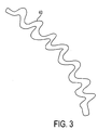
- the film 23 is "corrugated” or made with ridges and valleys along the length of the film 23.
- An example of this in Figure 3 shows the cross-section of one embodiment of a corrugated film 40.
- the number and width or frequency of the peaks and valleys can vary per each film used in a cable to optimize the characteristics and aspects of the films used.
- the "corrugation" of the films 40 greatly increases their sensitivity to the loads experienced during manufacture or installation.
- FIG 4 shows another embodiment of the present invention in another cable structure.
- the cable 30 has a glass reinforced center member 31, surrounded by six buffer tubes 32, each of which has a number of optical fibers 33.
- the cable 30 also has water absorbing tape 34, also known as swelling tape. This tape 34 absorbs moisture that enters the cable 30 preventing the moisture from propagating along the cable length and thus damaging the fibers or cable structure.
- a plurality of tactile or pressure sensitive film strips 35 are placed circumferentially around the cable, located between the outer jacket 36 and the buffer tubes 32.
- tactile films are wrapped around the buffer tubes and central strength member.
- the outer jacket of the cables made in accordance with this invention should be made from materials which allow one to see the color changes in the film or films used.
- the outer jacket is completely transparent so as to allow a clear view of the film to see any color change in the films.
Landscapes
- Physics & Mathematics (AREA)
- General Physics & Mathematics (AREA)
- Engineering & Computer Science (AREA)
- Optics & Photonics (AREA)
- Manufacturing & Machinery (AREA)
- Computer Security & Cryptography (AREA)
- Force Measurement Appropriate To Specific Purposes (AREA)
- Light Guides In General And Applications Therefor (AREA)
- Investigating Strength Of Materials By Application Of Mechanical Stress (AREA)
- Mechanical Coupling Of Light Guides (AREA)
Abstract
Description
Claims (22)
- A fiber optical cable (20), comprising:at least one optical fiber (21);an outer jacket (22); anda plurality of color-changing pressure sensitive films (23) positioned between said at least one optical fiber and said outer jacket, wherein said pressure sensitive films change color under stress.
- The optical fiber according to claim 1, wherein at least one of said color-changing pressure sensitive films is of smooth or corrugated shape.
- The optical fiber according to claim 1 or 2, wherein said outer jacket (22) is transparent.
- The optical fiber according to one of claims 1 to 3, further comprising at least one buffer tube(32), wherein said at least one optical fibers is disposed in said buffer tube, and said plurality of color changing pressure sensitive films are positioned between said at least one buffer tube and said outer jacket.
- The optical fiber according to one of claims 1 to 4, wherein said plurality of color changing pressure sensitive films are located at periodic intervals along the length of the fiber optic cable.
- The fiber optic cable according to one of claims 1 to 5, wherein said plurality of color changing pressure sensitive films are of the same width and length.
- The fiber optic cable according to one of claims 1 to 4, wherein said plurality of color changing pressure sensitive films are spaced evenly radially around the fiber optic cable.
- The fiber optic cable according to one of claims 1 to 4, wherein said plurality of color changing pressure sensitive films are spaced evenly along the length of the fiber optic cable.
- The fiber optic cable according to one of claims 1 to 4, wherein said plurality of color changing pressure sensitive films are spaced evenly along the length of and radially around the fiber optic cable.
- A fiber optical cable, comprising:wherein said plurality of color changing pressure sensitive films are located at periodic intervals throughout the fiber optic cable.an outer jacket (36);at least one buffer tube (32);at least one optical fiber (33), disposed in said at least one buffer tube; anda plurality of color-changing pressure sensitive films (35) positioned between said at least one optical fiber and said outer jacket, wherein said pressure sensitive films change color under stress;
- The fiber optic cable according to claim 10, wherein said plurality of color changing pressure sensitive films are corrugated.
- The fiber optic cable according to claim 10 or 11, wherein said outer jacket is transparent.
- The fiber optic cable according to claim 10, 11 or 12, wherein said plurality of color changing pressure sensitive films are of the same width and length.
- The fiber optic cable according to one of claims 10 to 14, wherein said plurality of color changing pressure sensitive films are spaced evenly radially around the fiber optic cable.
- The fiber optic cable according to one of claims 10 to 14, wherein said plurality of color changing pressure sensitive films are spaced evenly along the length of the fiber optic cable.
- The fiber optic cable according to one of claims 10 to 14, wherein said plurality of color changing pressure sensitive films are spaced evenly along the length of and radially around the fiber optic cable.
- A fiber optic cable, comprising:at least one optical fiber (33);an outer jacket (36); anda pressure sensitive film (35) positioned between said at least one optical fiber and said outer jacket, wherein said pressure sensitive film is corrugated and changes color under stress.
- A fiber optical cable, comprising:an outer jacket (36);at least one buffer tube (32);at least one optical fiber (33), disposed in said at least one buffer tube; anda color-changing pressure sensitive film (35) positioned between said at least one optical fiber and said outer jacket, wherein said pressure sensitive film is corrugated and changes color under stress.
- A fiber optic cable, comprising:wherein a color-changing pressure sensitive film (35) is wrapped around both said central strength member and said at least one buffer tube, wherein said pressure sensitive film changes color under stress.an outer jacket (36);at least one buffer tube (32), disposed in said outer jacket;at least one optical fiber (33), disposed in said at least one buffer tube; anda central strength member (31), disposed in said outer jacket adjacent to said at least one buffer tube;
- The optical fiber according to claim 19, wherein said pressure sensitive film is corrugated.
- A fiber optic cable, comprising:wherein a plurality of color-changing pressure sensitive films (35) are wrapped around both said central strength member and said at least one buffer tube, wherein said pressure sensitive films change color under stress.an outer jacket (36);at least one buffer tube (32), disposed in said outer jacket;at least one optical fiber (33), disposed in said at least one buffer tube; anda central strength member (31), disposed in said outer jacket adjacent to said at least one buffer tube;
- The optical fiber according to claim 20, wherein at least one of said pressure sensitive films is corrugated.
Applications Claiming Priority (2)
| Application Number | Priority Date | Filing Date | Title |
|---|---|---|---|
| US740938 | 2000-12-21 | ||
| US09/740,938 US6442316B1 (en) | 2000-12-21 | 2000-12-21 | Stress sensor based on periodically inserted color-changing tactile films to detect mishandling of fiber optic cables |
Publications (2)
| Publication Number | Publication Date |
|---|---|
| EP1217350A1 true EP1217350A1 (en) | 2002-06-26 |
| EP1217350B1 EP1217350B1 (en) | 2008-03-26 |
Family
ID=24978675
Family Applications (1)
| Application Number | Title | Priority Date | Filing Date |
|---|---|---|---|
| EP01403105A Expired - Lifetime EP1217350B1 (en) | 2000-12-21 | 2001-12-04 | Stress sensor based on periodically inserted color-changing tactile films to detect mishandling fiber optic cables |
Country Status (4)
| Country | Link |
|---|---|
| US (1) | US6442316B1 (en) |
| EP (1) | EP1217350B1 (en) |
| AT (1) | ATE390621T1 (en) |
| DE (1) | DE60133355D1 (en) |
Cited By (3)
| Publication number | Priority date | Publication date | Assignee | Title |
|---|---|---|---|---|
| DE202012006775U1 (en) | 2011-06-30 | 2013-07-15 | Fritz U. Bankwitz | Actuating element of an actuating unit for speed-dependent control of functions on two-wheeled vehicles, preferably height adjustment of the saddle |
| WO2015014385A1 (en) * | 2013-07-29 | 2015-02-05 | Prysmian S.P.A. | Optical cable for terrestrial networks |
| EP2275849A3 (en) * | 2009-06-26 | 2016-06-29 | Nexans | Fiber optic cable with clear buffer tubes |
Families Citing this family (14)
| Publication number | Priority date | Publication date | Assignee | Title |
|---|---|---|---|---|
| US6798956B2 (en) * | 2002-07-16 | 2004-09-28 | Sun Microsystems, Inc. | Optical cable with indicator |
| US7054531B2 (en) * | 2002-12-23 | 2006-05-30 | Corning Cable Systems Llc | High density fiber optic premises cable with easy open units |
| US8764996B2 (en) * | 2006-10-18 | 2014-07-01 | 3M Innovative Properties Company | Methods of patterning a material on polymeric substrates |
| US8685032B2 (en) | 2010-02-23 | 2014-04-01 | Cook Medical Technologies Llc | Pressure sensing vertebroplasty extension tube |
| CN101858803B (en) * | 2010-05-17 | 2011-10-26 | 哈尔滨工业大学 | Production and installation of subsurface structure forceon light-emitting and color-sensitive |
| US9085052B1 (en) | 2011-05-05 | 2015-07-21 | The Boeing Company | Structural repair having optical witness and method of monitoring repair performance |
| US8720278B1 (en) | 2011-05-05 | 2014-05-13 | The Boeing Company | Method of detecting inconsistencies in composite structures and stress sensitive coatings used therein |
| DE112012002423B4 (en) | 2011-06-10 | 2023-07-20 | Eaton Intelligent Power Limited | display device |
| US8912119B2 (en) | 2011-10-31 | 2014-12-16 | Intertape Polymer Corp. | Pressure-chromic tape and methods of making same |
| DE102012014033A1 (en) * | 2012-07-14 | 2014-01-16 | Carsten Jacobs | Line/wire tension indicator for indicating tension in e.g. cordage utilized as mooring line for ship, has display for colored displaying of load, and three signal threads changing color during changing of applied tension |
| US9244046B2 (en) | 2012-12-03 | 2016-01-26 | International Business Machines Corporation | System for preventing undue bending of cables |
| CN103487132A (en) * | 2013-08-29 | 2014-01-01 | 上海复旦智能监控成套设备有限公司 | Gravel buried type structure and method for amplifying optical fiber vibration sensing signals |
| US10768128B2 (en) | 2014-07-22 | 2020-09-08 | The Boeing Company | Systems and methods of monitoring a thermal protection system |
| US20220048626A1 (en) * | 2020-08-13 | 2022-02-17 | Boost Human External Cargo Systems Inc. | External load transport assembly for an aerial vehicle and use of the same for the construction and maintenance of power lines |
Citations (4)
| Publication number | Priority date | Publication date | Assignee | Title |
|---|---|---|---|---|
| US4138193A (en) * | 1977-09-27 | 1979-02-06 | General Cable Corporation | Multiple fiber laminate for optical waveguides |
| US4990769A (en) * | 1988-09-27 | 1991-02-05 | U.S. Philips Corp. | Continuous cable fiber optical pressure sensor |
| US5604318A (en) * | 1994-08-12 | 1997-02-18 | Waldemar Marinitsch | Optical pressure detector |
| EP0924543A2 (en) * | 1997-12-22 | 1999-06-23 | Lucent Technologies Inc. | Optical fiber cable having a stress indicating capability and process for making same |
Family Cites Families (6)
| Publication number | Priority date | Publication date | Assignee | Title |
|---|---|---|---|---|
| US4002139A (en) | 1974-08-05 | 1977-01-11 | Payne William J | Strain indicator |
| GB2063503B (en) | 1979-11-15 | 1983-05-11 | Standard Telephones Cables Ltd | Monitoring strain inoptic fibre cable |
| GB8619723D0 (en) | 1986-08-13 | 1986-09-24 | Hutchings I M | Load detection & indication |
| US5135262A (en) | 1990-06-20 | 1992-08-04 | Alcan International Limited | Method of making color change devices activatable by bending and product thereof |
| GB9116626D0 (en) | 1991-08-01 | 1991-09-18 | Univ Strathclyde | Improvements in and relating to ropes |
| US6278823B1 (en) * | 1999-03-09 | 2001-08-21 | Litton Systems, Inc. | Sensor array cable and fabrication method |
-
2000
- 2000-12-21 US US09/740,938 patent/US6442316B1/en not_active Expired - Fee Related
-
2001
- 2001-12-04 AT AT01403105T patent/ATE390621T1/en not_active IP Right Cessation
- 2001-12-04 DE DE60133355T patent/DE60133355D1/en not_active Expired - Lifetime
- 2001-12-04 EP EP01403105A patent/EP1217350B1/en not_active Expired - Lifetime
Patent Citations (4)
| Publication number | Priority date | Publication date | Assignee | Title |
|---|---|---|---|---|
| US4138193A (en) * | 1977-09-27 | 1979-02-06 | General Cable Corporation | Multiple fiber laminate for optical waveguides |
| US4990769A (en) * | 1988-09-27 | 1991-02-05 | U.S. Philips Corp. | Continuous cable fiber optical pressure sensor |
| US5604318A (en) * | 1994-08-12 | 1997-02-18 | Waldemar Marinitsch | Optical pressure detector |
| EP0924543A2 (en) * | 1997-12-22 | 1999-06-23 | Lucent Technologies Inc. | Optical fiber cable having a stress indicating capability and process for making same |
Cited By (4)
| Publication number | Priority date | Publication date | Assignee | Title |
|---|---|---|---|---|
| EP2275849A3 (en) * | 2009-06-26 | 2016-06-29 | Nexans | Fiber optic cable with clear buffer tubes |
| DE202012006775U1 (en) | 2011-06-30 | 2013-07-15 | Fritz U. Bankwitz | Actuating element of an actuating unit for speed-dependent control of functions on two-wheeled vehicles, preferably height adjustment of the saddle |
| WO2015014385A1 (en) * | 2013-07-29 | 2015-02-05 | Prysmian S.P.A. | Optical cable for terrestrial networks |
| US9715076B2 (en) | 2013-07-29 | 2017-07-25 | Prysmian S.P.A. | Optical cable for terrestrial networks |
Also Published As
| Publication number | Publication date |
|---|---|
| US20020081082A1 (en) | 2002-06-27 |
| EP1217350B1 (en) | 2008-03-26 |
| US6442316B1 (en) | 2002-08-27 |
| ATE390621T1 (en) | 2008-04-15 |
| DE60133355D1 (en) | 2008-05-08 |
Similar Documents
| Publication | Publication Date | Title |
|---|---|---|
| US6442316B1 (en) | Stress sensor based on periodically inserted color-changing tactile films to detect mishandling of fiber optic cables | |
| EP3665521B1 (en) | Rollable optical fiber ribbon with low attenuation, large mode field diameter optical fiber and cable | |
| CA3048873C (en) | Round and small diameter optical cables with a ribbon-like optical fiber structure | |
| US8380030B2 (en) | Bend-insensitive optical cable | |
| CN100580493C (en) | ribbon cable | |
| KR20190035719A (en) | Flexible fiber optic ribbon | |
| US10921541B2 (en) | Cylindrical enclosure for optical waveguide cable | |
| US5694497A (en) | Intrinsically self deforming fiber optic microbend pressure and strain sensor | |
| US11187866B2 (en) | Fiber multitube optical fiber cable | |
| EP0188512A1 (en) | A fibre-optic cable responsive to microbending forces. | |
| CN105301729A (en) | High strength and temperature sensitive optical cable | |
| WO2026066142A1 (en) | Optical fiber ribbon and optical cable | |
| EP3663825B1 (en) | Flat drop optical fiber cable | |
| JP3136946B2 (en) | Optical fiber cable and manufacturing method thereof | |
| CN100424536C (en) | A hybrid optical cable with sensing and communication functions and its manufacturing method | |
| EP4421549A2 (en) | Aerial drop optical fibre cable | |
| Buckler et al. | Atlanta fiber system experiment: Lightguide cable manufacture and performance | |
| KR100301776B1 (en) | Ribbon type optical sensor for measuring deformation of institution | |
| KR100339978B1 (en) | Optical sensor for measuring deformation of institution | |
| JPS6139365Y2 (en) | ||
| JP3024264B2 (en) | Optical waveguide element with built-in immersion sensor | |
| CN118111496A (en) | A strain-vibration-sensitive optical cable for pipelines | |
| CN121299864A (en) | A space-division multiplexing multi-core optical fiber cable for backbone networks | |
| JPH0247613A (en) | Coated optical fibers for optical fiber tape | |
| JPS61284627A (en) | Optical fiber sensor |
Legal Events
| Date | Code | Title | Description |
|---|---|---|---|
| PUAI | Public reference made under article 153(3) epc to a published international application that has entered the european phase |
Free format text: ORIGINAL CODE: 0009012 |
|
| AK | Designated contracting states |
Kind code of ref document: A1 Designated state(s): AT BE CH CY DE DK ES FI FR GB GR IE IT LI LU MC NL PT SE TR |
|
| AX | Request for extension of the european patent |
Free format text: AL;LT;LV;MK;RO;SI |
|
| 17P | Request for examination filed |
Effective date: 20021121 |
|
| AKX | Designation fees paid |
Designated state(s): AT BE CH CY DE DK ES FI FR GB GR IE IT LI LU MC NL PT SE TR |
|
| 17Q | First examination report despatched |
Effective date: 20041126 |
|
| RAP1 | Party data changed (applicant data changed or rights of an application transferred) |
Owner name: DRAKA COMTEQ B.V. |
|
| RAP1 | Party data changed (applicant data changed or rights of an application transferred) |
Owner name: DRAKA COMTEQ B.V. |
|
| RAP1 | Party data changed (applicant data changed or rights of an application transferred) |
Owner name: DRAKA COMTEQ B.V. |
|
| GRAP | Despatch of communication of intention to grant a patent |
Free format text: ORIGINAL CODE: EPIDOSNIGR1 |
|
| GRAS | Grant fee paid |
Free format text: ORIGINAL CODE: EPIDOSNIGR3 |
|
| GRAA | (expected) grant |
Free format text: ORIGINAL CODE: 0009210 |
|
| AK | Designated contracting states |
Kind code of ref document: B1 Designated state(s): AT BE CH CY DE DK ES FI FR GB GR IE IT LI LU MC NL PT SE TR |
|
| REG | Reference to a national code |
Ref country code: GB Ref legal event code: FG4D |
|
| REG | Reference to a national code |
Ref country code: IE Ref legal event code: FG4D Ref country code: CH Ref legal event code: EP |
|
| REF | Corresponds to: |
Ref document number: 60133355 Country of ref document: DE Date of ref document: 20080508 Kind code of ref document: P |
|
| PG25 | Lapsed in a contracting state [announced via postgrant information from national office to epo] |
Ref country code: FI Free format text: LAPSE BECAUSE OF FAILURE TO SUBMIT A TRANSLATION OF THE DESCRIPTION OR TO PAY THE FEE WITHIN THE PRESCRIBED TIME-LIMIT Effective date: 20080326 |
|
| PG25 | Lapsed in a contracting state [announced via postgrant information from national office to epo] |
Ref country code: AT Free format text: LAPSE BECAUSE OF FAILURE TO SUBMIT A TRANSLATION OF THE DESCRIPTION OR TO PAY THE FEE WITHIN THE PRESCRIBED TIME-LIMIT Effective date: 20080326 |
|
| NLV1 | Nl: lapsed or annulled due to failure to fulfill the requirements of art. 29p and 29m of the patents act | ||
| PG25 | Lapsed in a contracting state [announced via postgrant information from national office to epo] |
Ref country code: BE Free format text: LAPSE BECAUSE OF FAILURE TO SUBMIT A TRANSLATION OF THE DESCRIPTION OR TO PAY THE FEE WITHIN THE PRESCRIBED TIME-LIMIT Effective date: 20080326 |
|
| PG25 | Lapsed in a contracting state [announced via postgrant information from national office to epo] |
Ref country code: ES Free format text: LAPSE BECAUSE OF FAILURE TO SUBMIT A TRANSLATION OF THE DESCRIPTION OR TO PAY THE FEE WITHIN THE PRESCRIBED TIME-LIMIT Effective date: 20080707 Ref country code: SE Free format text: LAPSE BECAUSE OF FAILURE TO SUBMIT A TRANSLATION OF THE DESCRIPTION OR TO PAY THE FEE WITHIN THE PRESCRIBED TIME-LIMIT Effective date: 20080626 Ref country code: PT Free format text: LAPSE BECAUSE OF FAILURE TO SUBMIT A TRANSLATION OF THE DESCRIPTION OR TO PAY THE FEE WITHIN THE PRESCRIBED TIME-LIMIT Effective date: 20080901 |
|
| PG25 | Lapsed in a contracting state [announced via postgrant information from national office to epo] |
Ref country code: NL Free format text: LAPSE BECAUSE OF FAILURE TO SUBMIT A TRANSLATION OF THE DESCRIPTION OR TO PAY THE FEE WITHIN THE PRESCRIBED TIME-LIMIT Effective date: 20080326 |
|
| EN | Fr: translation not filed | ||
| PG25 | Lapsed in a contracting state [announced via postgrant information from national office to epo] |
Ref country code: DK Free format text: LAPSE BECAUSE OF FAILURE TO SUBMIT A TRANSLATION OF THE DESCRIPTION OR TO PAY THE FEE WITHIN THE PRESCRIBED TIME-LIMIT Effective date: 20080326 Ref country code: DE Free format text: LAPSE BECAUSE OF FAILURE TO SUBMIT A TRANSLATION OF THE DESCRIPTION OR TO PAY THE FEE WITHIN THE PRESCRIBED TIME-LIMIT Effective date: 20080627 |
|
| PLBE | No opposition filed within time limit |
Free format text: ORIGINAL CODE: 0009261 |
|
| STAA | Information on the status of an ep patent application or granted ep patent |
Free format text: STATUS: NO OPPOSITION FILED WITHIN TIME LIMIT |
|
| 26N | No opposition filed |
Effective date: 20081230 |
|
| PG25 | Lapsed in a contracting state [announced via postgrant information from national office to epo] |
Ref country code: FR Free format text: LAPSE BECAUSE OF FAILURE TO SUBMIT A TRANSLATION OF THE DESCRIPTION OR TO PAY THE FEE WITHIN THE PRESCRIBED TIME-LIMIT Effective date: 20090116 |
|
| PG25 | Lapsed in a contracting state [announced via postgrant information from national office to epo] |
Ref country code: MC Free format text: LAPSE BECAUSE OF NON-PAYMENT OF DUE FEES Effective date: 20081231 |
|
| REG | Reference to a national code |
Ref country code: CH Ref legal event code: PL |
|
| GBPC | Gb: european patent ceased through non-payment of renewal fee |
Effective date: 20081204 |
|
| PG25 | Lapsed in a contracting state [announced via postgrant information from national office to epo] |
Ref country code: IT Free format text: LAPSE BECAUSE OF FAILURE TO SUBMIT A TRANSLATION OF THE DESCRIPTION OR TO PAY THE FEE WITHIN THE PRESCRIBED TIME-LIMIT Effective date: 20080326 |
|
| PG25 | Lapsed in a contracting state [announced via postgrant information from national office to epo] |
Ref country code: CY Free format text: LAPSE BECAUSE OF FAILURE TO SUBMIT A TRANSLATION OF THE DESCRIPTION OR TO PAY THE FEE WITHIN THE PRESCRIBED TIME-LIMIT Effective date: 20080326 |
|
| PG25 | Lapsed in a contracting state [announced via postgrant information from national office to epo] |
Ref country code: IE Free format text: LAPSE BECAUSE OF NON-PAYMENT OF DUE FEES Effective date: 20081204 Ref country code: LI Free format text: LAPSE BECAUSE OF NON-PAYMENT OF DUE FEES Effective date: 20081231 Ref country code: CH Free format text: LAPSE BECAUSE OF NON-PAYMENT OF DUE FEES Effective date: 20081231 |
|
| PG25 | Lapsed in a contracting state [announced via postgrant information from national office to epo] |
Ref country code: GB Free format text: LAPSE BECAUSE OF NON-PAYMENT OF DUE FEES Effective date: 20081204 |
|
| PG25 | Lapsed in a contracting state [announced via postgrant information from national office to epo] |
Ref country code: LU Free format text: LAPSE BECAUSE OF NON-PAYMENT OF DUE FEES Effective date: 20081204 |
|
| PG25 | Lapsed in a contracting state [announced via postgrant information from national office to epo] |
Ref country code: TR Free format text: LAPSE BECAUSE OF FAILURE TO SUBMIT A TRANSLATION OF THE DESCRIPTION OR TO PAY THE FEE WITHIN THE PRESCRIBED TIME-LIMIT Effective date: 20080326 |
|
| PG25 | Lapsed in a contracting state [announced via postgrant information from national office to epo] |
Ref country code: GR Free format text: LAPSE BECAUSE OF FAILURE TO SUBMIT A TRANSLATION OF THE DESCRIPTION OR TO PAY THE FEE WITHIN THE PRESCRIBED TIME-LIMIT Effective date: 20080627 |