EP1217296A1 - Vaporising oil burners - Google Patents
Vaporising oil burners Download PDFInfo
- Publication number
- EP1217296A1 EP1217296A1 EP00311502A EP00311502A EP1217296A1 EP 1217296 A1 EP1217296 A1 EP 1217296A1 EP 00311502 A EP00311502 A EP 00311502A EP 00311502 A EP00311502 A EP 00311502A EP 1217296 A1 EP1217296 A1 EP 1217296A1
- Authority
- EP
- European Patent Office
- Prior art keywords
- inlet pipe
- pipe
- oil
- chamber
- assembly according
- Prior art date
- Legal status (The legal status is an assumption and is not a legal conclusion. Google has not performed a legal analysis and makes no representation as to the accuracy of the status listed.)
- Withdrawn
Links
- OKTJSMMVPCPJKN-UHFFFAOYSA-N Carbon Chemical compound [C] OKTJSMMVPCPJKN-UHFFFAOYSA-N 0.000 claims abstract description 14
- 229910052799 carbon Inorganic materials 0.000 claims abstract description 14
- 238000009825 accumulation Methods 0.000 claims abstract description 5
- 238000011144 upstream manufacturing Methods 0.000 claims description 7
- 238000009413 insulation Methods 0.000 claims description 6
- WYTGDNHDOZPMIW-RCBQFDQVSA-N alstonine Natural products C1=CC2=C3C=CC=CC3=NC2=C2N1C[C@H]1[C@H](C)OC=C(C(=O)OC)[C@H]1C2 WYTGDNHDOZPMIW-RCBQFDQVSA-N 0.000 claims description 3
- 230000015572 biosynthetic process Effects 0.000 claims description 3
- 229910001220 stainless steel Inorganic materials 0.000 claims description 3
- 239000010935 stainless steel Substances 0.000 claims description 3
- 238000002485 combustion reaction Methods 0.000 claims description 2
- 239000000463 material Substances 0.000 claims 2
- 239000011810 insulating material Substances 0.000 claims 1
- 238000004140 cleaning Methods 0.000 abstract description 5
- 210000002445 nipple Anatomy 0.000 description 9
- 239000000446 fuel Substances 0.000 description 5
- 238000005266 casting Methods 0.000 description 3
- 239000004927 clay Substances 0.000 description 2
- 238000010276 construction Methods 0.000 description 2
- 230000000694 effects Effects 0.000 description 2
- VNWKTOKETHGBQD-UHFFFAOYSA-N methane Chemical compound C VNWKTOKETHGBQD-UHFFFAOYSA-N 0.000 description 2
- 238000007789 sealing Methods 0.000 description 2
- 229910000898 sterling silver Inorganic materials 0.000 description 2
- 239000010934 sterling silver Substances 0.000 description 2
- 229910000639 Spring steel Inorganic materials 0.000 description 1
- 238000005219 brazing Methods 0.000 description 1
- 239000002131 composite material Substances 0.000 description 1
- 238000001816 cooling Methods 0.000 description 1
- 239000007789 gas Substances 0.000 description 1
- 210000004907 gland Anatomy 0.000 description 1
- 238000010438 heat treatment Methods 0.000 description 1
- 238000000034 method Methods 0.000 description 1
- 238000012986 modification Methods 0.000 description 1
- 230000004048 modification Effects 0.000 description 1
- 239000003345 natural gas Substances 0.000 description 1
- 238000013021 overheating Methods 0.000 description 1
- 230000035515 penetration Effects 0.000 description 1
- 238000007790 scraping Methods 0.000 description 1
- 238000005476 soldering Methods 0.000 description 1
- 238000003466 welding Methods 0.000 description 1
Images

Classifications
-
- F—MECHANICAL ENGINEERING; LIGHTING; HEATING; WEAPONS; BLASTING
- F23—COMBUSTION APPARATUS; COMBUSTION PROCESSES
- F23D—BURNERS
- F23D5/00—Burners in which liquid fuel evaporates in the combustion space, with or without chemical conversion of evaporated fuel
- F23D5/12—Details
Definitions
- This invention relates to a vaporising oil burner and to an assembly for attaching the downstream end of an oil inlet pipe to a vaporising chamber of such a burner.
- Cookers and similar heating appliances are commonly fired by vaporising oil burners, particularly where natural gas is not available.
- Such burners suffer from an accumulation of carbon-like deposits in the oil inlet pipes supplying the oil to the vaporising chambers of the burners. These deposits also tend to form over the outlet of the oil inlet pipe where it debouches into the vaporising chamber of the burner. Accumulation of deposits within the oil inlet pipe is particularly pronounced where the temperature of the pipe is highest, typically at its downstream end where it is close to the vaporising chamber.
- the invention aims to solve this problem.
- an assembly for attaching the downstream end of an oil inlet pipe to a vaporising chamber of a vaporising oil burner, the assembly permitting attachment of the oil inlet pipe to the chamber in a manner providing thermal insulation between the vaporising chamber and the oil inlet pipe, in order to reduce or eliminate the formation of carbon deposits in the pipe during use.
- the thermal insulation keeps the inlet pipe cool, thereby preventing (or reducing) the accumulation of carbon deposits in the bore of the inlet pipe.
- the assembly includes a portion of the length of the oil inlet pipe at the downstream end thereof.
- the assembly may include a mounting sleeve formed for reception in an aperture in a wall of the vaporising chamber, the mounting sleeve surrounding said portion of the inlet pipe with clearance which contributes to said thermal insulation.
- the mounting sleeve may be formed with external threads for threading into the aperture, the sleeve surrounding the portion of the inlet pipe with all-round radial clearance.
- a tube surrounds the portion of the pipe with radial clearance and is in turn surrounded by the sleeve, the downstream end of the sleeve being attached to the downstream end of the tube and the pipe portion being supported by the upstream end of the tube which projects outwardly of the sleeve in an upstream direction so that there is a serpentine or convoluted conductive heat flow path between the sleeve and the portion of the length of the oil inlet pipe.
- the assembly may include a cleaning rod inserted into the oil inlet pipe.
- the rod can be moved in the inlet pipe with a reciprocating and rotating motion, to dislodge any carbon deposits. This can be done on a regular basis or when the performance of the burner begins to deteriorate.
- the vaporising oil burner typically forms part of an Aga (registered trade mark) cooker or other oil burning appliance.
- the burner has a base casting 2 defining a vaporising chamber 3 closed by a cap 4.
- the casting 2 is installed above a burner firebox floor 1.
- the wicks used for lighting the burner are illustrated at 5.
- One side wall of the casting 2 has a tapped hole receiving a sleeve in the form of a threaded hexagon nipple 6 the inner end of which projects into the chamber 3.
- the nipple 6 supports, by means of an annular body of fire-clay forming a seal 7, the downstream end of an oil inlet pipe 8.
- Between the oil inlet pipe 8 and the nipple 6 is a circular-section stainless steel tube 9.
- the seal 7 thus closes off the downstream end of the annular space between the oil inlet pipe 8 and the tube 9. Unwanted penetration of the fire-clay into this annular space can be prevented by means of a washer.
- the tube 9 is attached to the inner end of the nipple 6 and at its upstream end the tube 9 supports the inlet pipe by means of a sleeve or ferrule 10 soldered or brazed in position.
- the nipple 6 surrounds the tube 9 with all-round radial clearance (apart from at the extreme downstream end of the nipple 6) and the tube 9 surrounds the pipe 8 with all-round radial clearance, apart from at the upstream and downstream ends of the tube 9.
- a spring steel cleaning rod 12 may form part of the assembly.
- the rod 12 has an outer end carrying a formation 13 for ease of grasping and its inner end 14 can be moved through the bore of the inlet pipe to clean the latter of any carbon deposits which might build up in the bore of, or at the downstream end of, the inlet pipe.
- the rod 12 passes through a fuel elbow 15 which directs oil from a supply pipe 16 to the inlet pipe 8.
- a packed gland can be tightened by a nut 17 to prevent oil leakage at the point where the rod 12 enters the fuel elbow 15.
- the rod 12 may incorporate a slight bend to increase the frictional engagement of the inner end of the rod with the bore of the inlet pipe 8 so as to improve the scraping or cleaning effect of the rod which has sufficient length for the inner end 14 to project into the vaporising chamber.
- the rod not only clears the bore of the inlet pipe 8 but also dislodges any carbon deposits which might tend to form on the downstream end of the inlet pipe 8.
- the pipe 8 debouches into the chamber 3 at a position above the base thereof, so that any carbon deposits which are dislodged by the rod 12 fall into the base of the vaporising chamber.
- the inlet pipe 8 In its length between the elbow and the chamber, the inlet pipe 8 preferably passes through a rectangular section air duct 18 which has open ends and guides combustion air towards the burner of the cooker. This flow of air through the duct helps to cool the inlet pipe 8.
- the duct 18 is shown in broken lines in Figure 1 to illustrate its position, when fitted.
- the inlet pipe is of composite construction, having a main portion 8a and a smaller downstream portion 8b made of sterling silver.
- the portions 8a and 8b are joined by a soldered bush 19.
- the purpose of the sterling silver which has a very high thermal conductivity, is to reduce the possibility of localised overheating at the extreme downstream end of the inlet pipe where it is exposed to the highest temperatures.
- Typical dimensions are: for the pipe 8, 6mm outside diameter and 4.8mm internal diameter; for the rod 12, 3.00mm diameter.
- the fireclay seal 7 which is both moderately fragile and also slightly permeable to fuel may be replaced with a high-temperature-resisting plastic washer either force fit or glued into the annular gap between the inner end of nipple 6 and the downstream end of oil inlet pipe 8.
- the seal 7 can be replaced by a very thin stainless steel washer with its outer circumference attached to the inner end of nipple 6 and/or the dowstream end of tube 9 by soldering, brazing or welding and its inner aperture similarly attached to the downstream end of oil inlet pipe 8.
- This latter method provides for an hermetic sealing of the annular space between oil inlet pipe 8 and outer tube 9 against unwanted ingress of fuel and/or fuel vapour and further allows this annular space to be either partially or totally evacuated of air or gas before sealing thus affording the additional advantage of reducing conductive heat flow in the annular gap.
- An existing cooker can be modified by the fitting of an assembly according to the invention, or the assembly can be fitted as original equipment.
- the tendency for carbon to be deposited in or at the end of the pipe 8 is minimised because the pipe is kept at a lower temperature than hitherto, mainly as a consequence of the serpentine conductive heat flow path between the nipple 6 and the downstream portion of the oil inlet pipe surrounded by the tube 9, but also by the cooling effect of the air passing through the duct 18.
- Any carbon which does form in or at the end of the inlet pipe 8 can be dislodged by use of the rod 12, the carbon so dislodged falling into the base of the chamber 3 which can at intervals be cleaned.
Landscapes
- Engineering & Computer Science (AREA)
- Chemical & Material Sciences (AREA)
- Combustion & Propulsion (AREA)
- Mechanical Engineering (AREA)
- General Engineering & Computer Science (AREA)
- Nozzles For Spraying Of Liquid Fuel (AREA)
Abstract
Description
- This invention relates to a vaporising oil burner and to an assembly for attaching the downstream end of an oil inlet pipe to a vaporising chamber of such a burner.
- Cookers and similar heating appliances are commonly fired by vaporising oil burners, particularly where natural gas is not available. Such burners suffer from an accumulation of carbon-like deposits in the oil inlet pipes supplying the oil to the vaporising chambers of the burners. These deposits also tend to form over the outlet of the oil inlet pipe where it debouches into the vaporising chamber of the burner. Accumulation of deposits within the oil inlet pipe is particularly pronounced where the temperature of the pipe is highest, typically at its downstream end where it is close to the vaporising chamber. The invention aims to solve this problem.
- According to one aspect of the invention there is provided an assembly for attaching the downstream end of an oil inlet pipe to a vaporising chamber of a vaporising oil burner, the assembly permitting attachment of the oil inlet pipe to the chamber in a manner providing thermal insulation between the vaporising chamber and the oil inlet pipe, in order to reduce or eliminate the formation of carbon deposits in the pipe during use. The thermal insulation keeps the inlet pipe cool, thereby preventing (or reducing) the accumulation of carbon deposits in the bore of the inlet pipe.
- Preferably the assembly includes a portion of the length of the oil inlet pipe at the downstream end thereof.
- The assembly may include a mounting sleeve formed for reception in an aperture in a wall of the vaporising chamber, the mounting sleeve surrounding said portion of the inlet pipe with clearance which contributes to said thermal insulation. The mounting sleeve may be formed with external threads for threading into the aperture, the sleeve surrounding the portion of the inlet pipe with all-round radial clearance.
- In the preferred embodiment, a tube surrounds the portion of the pipe with radial clearance and is in turn surrounded by the sleeve, the downstream end of the sleeve being attached to the downstream end of the tube and the pipe portion being supported by the upstream end of the tube which projects outwardly of the sleeve in an upstream direction so that there is a serpentine or convoluted conductive heat flow path between the sleeve and the portion of the length of the oil inlet pipe.
- To enable the removal of any deposits which do form in or at the end of the inlet pipe, the assembly may include a cleaning rod inserted into the oil inlet pipe. The rod can be moved in the inlet pipe with a reciprocating and rotating motion, to dislodge any carbon deposits. This can be done on a regular basis or when the performance of the burner begins to deteriorate.
- The invention will now be further described, by way of example, with reference to the accompanying drawings, in which:
- Figure 1 is a fragmentary view, partly in section, showing a vaporising oil burner fitted with an assembly according to the invention,
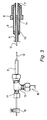
- Figure 2 is a fragmentary sectional view through the assembly of Figure 1,
- Figure 3 illustrates an optional cleaning rod of the assembly,
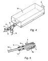
- Figure 4 illustrates an optional duct of the assembly, and
- Figure 5 is a sectional view corresponding to that of Figure 2 but showing a modified construction also in accordance with the invention.
-
- The vaporising oil burner typically forms part of an Aga (registered trade mark) cooker or other oil burning appliance. The burner has a
base casting 2 defining a vaporisingchamber 3 closed by a cap 4. Thecasting 2 is installed above a burner firebox floor 1. The wicks used for lighting the burner are illustrated at 5. One side wall of thecasting 2 has a tapped hole receiving a sleeve in the form of a threadedhexagon nipple 6 the inner end of which projects into thechamber 3. At this inner end thenipple 6 supports, by means of an annular body of fire-clay forming a seal 7, the downstream end of anoil inlet pipe 8. Between theoil inlet pipe 8 and thenipple 6 is a circular-sectionstainless steel tube 9. The seal 7 thus closes off the downstream end of the annular space between theoil inlet pipe 8 and thetube 9. Unwanted penetration of the fire-clay into this annular space can be prevented by means of a washer. At its downstream end, thetube 9 is attached to the inner end of thenipple 6 and at its upstream end thetube 9 supports the inlet pipe by means of a sleeve orferrule 10 soldered or brazed in position. As best shown in Figure 2, thenipple 6 surrounds thetube 9 with all-round radial clearance (apart from at the extreme downstream end of the nipple 6) and thetube 9 surrounds thepipe 8 with all-round radial clearance, apart from at the upstream and downstream ends of thetube 9. - Referring to Figure 3, a spring
steel cleaning rod 12 may form part of the assembly. Therod 12 has an outer end carrying aformation 13 for ease of grasping and itsinner end 14 can be moved through the bore of the inlet pipe to clean the latter of any carbon deposits which might build up in the bore of, or at the downstream end of, the inlet pipe. Therod 12 passes through afuel elbow 15 which directs oil from asupply pipe 16 to theinlet pipe 8. A packed gland can be tightened by anut 17 to prevent oil leakage at the point where therod 12 enters thefuel elbow 15. At a point near itsend 14, therod 12 may incorporate a slight bend to increase the frictional engagement of the inner end of the rod with the bore of theinlet pipe 8 so as to improve the scraping or cleaning effect of the rod which has sufficient length for theinner end 14 to project into the vaporising chamber. Thus, the rod not only clears the bore of theinlet pipe 8 but also dislodges any carbon deposits which might tend to form on the downstream end of theinlet pipe 8. Thepipe 8 debouches into thechamber 3 at a position above the base thereof, so that any carbon deposits which are dislodged by therod 12 fall into the base of the vaporising chamber. - In its length between the elbow and the chamber, the
inlet pipe 8 preferably passes through a rectangularsection air duct 18 which has open ends and guides combustion air towards the burner of the cooker. This flow of air through the duct helps to cool theinlet pipe 8. Theduct 18 is shown in broken lines in Figure 1 to illustrate its position, when fitted. - In the modification of Figure 5, the inlet pipe is of composite construction, having a
main portion 8a and a smallerdownstream portion 8b made of sterling silver. Theportions bush 19. The purpose of the sterling silver, which has a very high thermal conductivity, is to reduce the possibility of localised overheating at the extreme downstream end of the inlet pipe where it is exposed to the highest temperatures. - Typical dimensions are: for the
pipe 8, 6mm outside diameter and 4.8mm internal diameter; for therod 12, 3.00mm diameter. - The fireclay seal 7 which is both moderately fragile and also slightly permeable to fuel may be replaced with a high-temperature-resisting plastic washer either force fit or glued into the annular gap between the inner end of
nipple 6 and the downstream end ofoil inlet pipe 8. As a further alternative, the seal 7 can be replaced by a very thin stainless steel washer with its outer circumference attached to the inner end ofnipple 6 and/or the dowstream end oftube 9 by soldering, brazing or welding and its inner aperture similarly attached to the downstream end ofoil inlet pipe 8. This latter method provides for an hermetic sealing of the annular space betweenoil inlet pipe 8 andouter tube 9 against unwanted ingress of fuel and/or fuel vapour and further allows this annular space to be either partially or totally evacuated of air or gas before sealing thus affording the additional advantage of reducing conductive heat flow in the annular gap. - An existing cooker can be modified by the fitting of an assembly according to the invention, or the assembly can be fitted as original equipment. In either case, the tendency for carbon to be deposited in or at the end of the
pipe 8 is minimised because the pipe is kept at a lower temperature than hitherto, mainly as a consequence of the serpentine conductive heat flow path between thenipple 6 and the downstream portion of the oil inlet pipe surrounded by thetube 9, but also by the cooling effect of the air passing through theduct 18. Any carbon which does form in or at the end of theinlet pipe 8 can be dislodged by use of therod 12, the carbon so dislodged falling into the base of thechamber 3 which can at intervals be cleaned.
Claims (15)
- An assembly for attaching the downstream end of an oil inlet pipe to a vaporising chamber of a vaporising oil burner, the assembly permitting attachment of the oil inlet pipe to the chamber in a manner providing thermal insulation between the vaporising chamber and the oil inlet pipe, in order to reduce or eliminate the formation of carbon deposits in the pipe during use.
- An assembly according to claim 1, wherein the assembly includes a portion of the length of the oil inlet pipe at the downstream end thereof.
- An assembly according to claim 2, wherein the assembly includes a mounting sleeve formed for reception in an aperture in a wall of the vaporising chamber, the mounting sleeve surrounding said portion of the inlet pipe with clearance which contributes to said thermal insulation.
- An assembly according to claim 3, wherein the mounting sleeve is formed with external threads for threading into the aperture, the sleeve surrounding the portion of the inlet pipe with all-round radial clearance.
- An assembly according to claim 3 or 4, wherein a tube surrounds the portion of the pipe with radial clearance and is in turn surrounded by the sleeve, the downstream end of the sleeve being attached to the downstream end of the tube and the pipe portion being supported by the upstream end of the tube which projects outwardly of the sleeve in an upstream direction so that there is a serpentine or convoluted conductive heat flow path between the sleeve and the portion of the length of the oil inlet pipe.
- An assembly according to claim 5, wherein the downstream end of the annular space between the pipe and tube is sealed by a body of an insulating material, such as fireclay.
- An assembly according to claim 5 or 6, wherein the tube is made of a material, such as stainless steel, having a poor thermal conductivity in comparison with the thermal conductivity of the oil inlet pipe.
- An assembly according to claim 7, wherein the pipe is supported in the upstream end of the tube by a sleeve or ferrule.
- An assembly according to any of the preceding claims and including a rod inserted into the oil inlet pipe to dislodge carbon deposits in or at the end of the pipe and to push such deposits into the vaporising chamber.
- An assembly according to claim 9, wherein the rod is bent at an intermediate point along its length to increase the frictional engagement of the rod within the bore of the inlet pipe, and, by rotation of the rod, to allow a greater portion of the bore to be scraped by the rod.
- An assembly according to any of the preceding claims, wherein the downstream length of the oil inlet pipe is made of a material of a higher thermal conductivity than the remainder of the length of the oil inlet pipe.
- An assembly according to any of the preceding claims and including a duct which surrounds the inlet pipe and is operative to guide incoming combustion air past the inlet pipe to cool the latter.
- An assembly according to any of the preceding claims and fitted to a vaporising oil burner in a cooker or other oil burning appliance.
- A vaporising oil burner comprising a vaporising chamber and an inlet pipe for supplying oil to the chamber, a downstream end of the pipe being attached to the burner with the provision of thermal insulation between the chamber and the oil inlet pipe, in order to reduce the accumulation of carbon deposits in the pipe during use.
- A vaporising oil burner according to claim 14, wherein the downstream end of the pipe debouches into the chamber at a position above the base of the chamber, so that carbon deposits can accumulate in the chamber to a substantial depth before impeding the flow of oil through the inlet pipe.
Priority Applications (1)
| Application Number | Priority Date | Filing Date | Title |
|---|---|---|---|
| EP00311502A EP1217296A1 (en) | 2000-12-20 | 2000-12-20 | Vaporising oil burners |
Applications Claiming Priority (1)
| Application Number | Priority Date | Filing Date | Title |
|---|---|---|---|
| EP00311502A EP1217296A1 (en) | 2000-12-20 | 2000-12-20 | Vaporising oil burners |
Publications (1)
| Publication Number | Publication Date |
|---|---|
| EP1217296A1 true EP1217296A1 (en) | 2002-06-26 |
Family
ID=8173474
Family Applications (1)
| Application Number | Title | Priority Date | Filing Date |
|---|---|---|---|
| EP00311502A Withdrawn EP1217296A1 (en) | 2000-12-20 | 2000-12-20 | Vaporising oil burners |
Country Status (1)
| Country | Link |
|---|---|
| EP (1) | EP1217296A1 (en) |
Citations (5)
| Publication number | Priority date | Publication date | Assignee | Title |
|---|---|---|---|---|
| GB789921A (en) * | 1955-02-05 | 1958-01-29 | Burger Eisenwerke Gmbh | Improvements in or relating to oil burners |
| FR1473571A (en) * | 1967-06-05 | |||
| DE2510903A1 (en) * | 1975-03-13 | 1976-09-30 | Andreas Meng | Burner tube for furnaces with side nozzle - has cooled nozzle assembly for ensuring flexibility of nozzle seals |
| JPS6030903A (en) * | 1983-07-29 | 1985-02-16 | Sanpotsuto Kk | Vaporization type burner |
| GB2275525A (en) * | 1993-02-24 | 1994-08-31 | Herbert Edward Boulter | Vaporizing oil burners |
-
2000
- 2000-12-20 EP EP00311502A patent/EP1217296A1/en not_active Withdrawn
Patent Citations (5)
| Publication number | Priority date | Publication date | Assignee | Title |
|---|---|---|---|---|
| FR1473571A (en) * | 1967-06-05 | |||
| GB789921A (en) * | 1955-02-05 | 1958-01-29 | Burger Eisenwerke Gmbh | Improvements in or relating to oil burners |
| DE2510903A1 (en) * | 1975-03-13 | 1976-09-30 | Andreas Meng | Burner tube for furnaces with side nozzle - has cooled nozzle assembly for ensuring flexibility of nozzle seals |
| JPS6030903A (en) * | 1983-07-29 | 1985-02-16 | Sanpotsuto Kk | Vaporization type burner |
| GB2275525A (en) * | 1993-02-24 | 1994-08-31 | Herbert Edward Boulter | Vaporizing oil burners |
Non-Patent Citations (1)
| Title |
|---|
| PATENT ABSTRACTS OF JAPAN vol. 009, no. 155 (M - 392) 29 June 1985 (1985-06-29) * |
Similar Documents
| Publication | Publication Date | Title |
|---|---|---|
| US4329943A (en) | Heating boiler | |
| JP4686458B2 (en) | Measuring feeler | |
| JP2011220343A (en) | Fuel heater | |
| US20100101509A1 (en) | Water heaters with sealed door assemblies | |
| US5131351A (en) | Heat exchanger plug | |
| GB2354565A (en) | Assembly for providing thermal insulation between the vaporising chamber of an oil burner and an inlet pipe | |
| US11846449B2 (en) | Combustion systems with ease of serviceability | |
| JP2004044899A (en) | Defrosting heater for household refrigerator | |
| US4003407A (en) | Drip-preventing condensation shroud usable with water heaters | |
| CN213066581U (en) | Heat Exchangers and Hot Water Units | |
| EP1692387B1 (en) | A stirling engine assembly | |
| US20040096794A1 (en) | Radiant tube gas burner | |
| CN114061150A (en) | Heat exchanger and water heating apparatus | |
| KR200245167Y1 (en) | Vacuum line heating device | |
| EP0499760B1 (en) | Boiler and installation for central heating and/or production of hot water | |
| SU655870A2 (en) | Quick-release pipe connection | |
| RU2007115070A (en) | ELEMENT FOR CATALYTIC GAS BURNING AND HEATING DEVICE FUED BY GAS ENERGY | |
| KR200232566Y1 (en) | apparatus of fried food used for prevention of overheating | |
| FR2616894A1 (en) | Heat-exchange and sound-proofing device for a boiler | |
| JP2003042430A (en) | Soot blower | |
| KR100570287B1 (en) | Gas Boiler Heat Exchanger | |
| KR200241728Y1 (en) | Anti-shake structure of copper coil for boiler | |
| FR2750140A1 (en) | SPRAYING SYSTEM WITH EROSION PROTECTION MEANS | |
| US2019458A (en) | Water heater | |
| KR850001306B1 (en) | Burners where liquid fuel burns in gaseous state |
Legal Events
| Date | Code | Title | Description |
|---|---|---|---|
| PUAI | Public reference made under article 153(3) epc to a published international application that has entered the european phase |
Free format text: ORIGINAL CODE: 0009012 |
|
| AK | Designated contracting states |
Kind code of ref document: A1 Designated state(s): AT BE CH CY DE DK ES FI FR GB GR IE IT LI LU MC NL PT SE TR |
|
| AX | Request for extension of the european patent |
Free format text: AL;LT;LV;MK;RO;SI |
|
| RAP1 | Party data changed (applicant data changed or rights of an application transferred) |
Owner name: KEITH W NASH & CO. Owner name: HARVEY, GEOFFREY PHILIP |
|
| AKX | Designation fees paid | ||
| REG | Reference to a national code |
Ref country code: DE Ref legal event code: 8566 |
|
| STAA | Information on the status of an ep patent application or granted ep patent |
Free format text: STATUS: THE APPLICATION IS DEEMED TO BE WITHDRAWN |
|
| 18D | Application deemed to be withdrawn |
Effective date: 20021227 |