EP1217259A1 - Pulley unit - Google Patents
Pulley unit Download PDFInfo
- Publication number
- EP1217259A1 EP1217259A1 EP01984437A EP01984437A EP1217259A1 EP 1217259 A1 EP1217259 A1 EP 1217259A1 EP 01984437 A EP01984437 A EP 01984437A EP 01984437 A EP01984437 A EP 01984437A EP 1217259 A1 EP1217259 A1 EP 1217259A1
- Authority
- EP
- European Patent Office
- Prior art keywords
- pulley
- way clutch
- lubricating oil
- axially
- retainer
- Prior art date
- Legal status (The legal status is an assumption and is not a legal conclusion. Google has not performed a legal analysis and makes no representation as to the accuracy of the status listed.)
- Granted
Links
Images



Classifications
-
- F—MECHANICAL ENGINEERING; LIGHTING; HEATING; WEAPONS; BLASTING
- F16—ENGINEERING ELEMENTS AND UNITS; GENERAL MEASURES FOR PRODUCING AND MAINTAINING EFFECTIVE FUNCTIONING OF MACHINES OR INSTALLATIONS; THERMAL INSULATION IN GENERAL
- F16D—COUPLINGS FOR TRANSMITTING ROTATION; CLUTCHES; BRAKES
- F16D41/00—Freewheels or freewheel clutches
- F16D41/06—Freewheels or freewheel clutches with intermediate wedging coupling members between an inner and an outer surface
- F16D41/064—Freewheels or freewheel clutches with intermediate wedging coupling members between an inner and an outer surface the intermediate members wedging by rolling and having a circular cross-section, e.g. balls
- F16D41/066—Freewheels or freewheel clutches with intermediate wedging coupling members between an inner and an outer surface the intermediate members wedging by rolling and having a circular cross-section, e.g. balls all members having the same size and only one of the two surfaces being cylindrical
- F16D41/067—Freewheels or freewheel clutches with intermediate wedging coupling members between an inner and an outer surface the intermediate members wedging by rolling and having a circular cross-section, e.g. balls all members having the same size and only one of the two surfaces being cylindrical and the members being distributed by a separate cage encircling the axis of rotation
-
- F—MECHANICAL ENGINEERING; LIGHTING; HEATING; WEAPONS; BLASTING
- F16—ENGINEERING ELEMENTS AND UNITS; GENERAL MEASURES FOR PRODUCING AND MAINTAINING EFFECTIVE FUNCTIONING OF MACHINES OR INSTALLATIONS; THERMAL INSULATION IN GENERAL
- F16H—GEARING
- F16H55/00—Elements with teeth or friction surfaces for conveying motion; Worms, pulleys or sheaves for gearing mechanisms
- F16H55/32—Friction members
- F16H55/36—Pulleys
-
- F—MECHANICAL ENGINEERING; LIGHTING; HEATING; WEAPONS; BLASTING
- F16—ENGINEERING ELEMENTS AND UNITS; GENERAL MEASURES FOR PRODUCING AND MAINTAINING EFFECTIVE FUNCTIONING OF MACHINES OR INSTALLATIONS; THERMAL INSULATION IN GENERAL
- F16H—GEARING
- F16H55/00—Elements with teeth or friction surfaces for conveying motion; Worms, pulleys or sheaves for gearing mechanisms
- F16H55/32—Friction members
- F16H55/36—Pulleys
- F16H55/49—Features essential to V-belts pulleys
-
- F—MECHANICAL ENGINEERING; LIGHTING; HEATING; WEAPONS; BLASTING
- F16—ENGINEERING ELEMENTS AND UNITS; GENERAL MEASURES FOR PRODUCING AND MAINTAINING EFFECTIVE FUNCTIONING OF MACHINES OR INSTALLATIONS; THERMAL INSULATION IN GENERAL
- F16C—SHAFTS; FLEXIBLE SHAFTS; ELEMENTS OR CRANKSHAFT MECHANISMS; ROTARY BODIES OTHER THAN GEARING ELEMENTS; BEARINGS
- F16C19/00—Bearings with rolling contact, for exclusively rotary movement
- F16C19/49—Bearings with both balls and rollers
-
- F—MECHANICAL ENGINEERING; LIGHTING; HEATING; WEAPONS; BLASTING
- F16—ENGINEERING ELEMENTS AND UNITS; GENERAL MEASURES FOR PRODUCING AND MAINTAINING EFFECTIVE FUNCTIONING OF MACHINES OR INSTALLATIONS; THERMAL INSULATION IN GENERAL
- F16C—SHAFTS; FLEXIBLE SHAFTS; ELEMENTS OR CRANKSHAFT MECHANISMS; ROTARY BODIES OTHER THAN GEARING ELEMENTS; BEARINGS
- F16C2361/00—Apparatus or articles in engineering in general
- F16C2361/63—Gears with belts and pulleys
-
- F—MECHANICAL ENGINEERING; LIGHTING; HEATING; WEAPONS; BLASTING
- F16—ENGINEERING ELEMENTS AND UNITS; GENERAL MEASURES FOR PRODUCING AND MAINTAINING EFFECTIVE FUNCTIONING OF MACHINES OR INSTALLATIONS; THERMAL INSULATION IN GENERAL
- F16D—COUPLINGS FOR TRANSMITTING ROTATION; CLUTCHES; BRAKES
- F16D41/00—Freewheels or freewheel clutches
- F16D41/06—Freewheels or freewheel clutches with intermediate wedging coupling members between an inner and an outer surface
- F16D2041/0608—Races with a regular polygon shape
-
- F—MECHANICAL ENGINEERING; LIGHTING; HEATING; WEAPONS; BLASTING
- F16—ENGINEERING ELEMENTS AND UNITS; GENERAL MEASURES FOR PRODUCING AND MAINTAINING EFFECTIVE FUNCTIONING OF MACHINES OR INSTALLATIONS; THERMAL INSULATION IN GENERAL
- F16H—GEARING
- F16H55/00—Elements with teeth or friction surfaces for conveying motion; Worms, pulleys or sheaves for gearing mechanisms
- F16H55/32—Friction members
- F16H55/36—Pulleys
- F16H2055/366—Pulleys with means providing resilience or vibration damping
Definitions
- the present invention relates to a pulley unit having a one-way clutch.
- the pulley unit can be mounted in an auxiliary machine which is driven by a crankshaft of an engine of an automobile or the like through a belt.
- the auxiliary machine are an air conditioner compressor, a water pump, an alternator, a cooling fan and the like of an automobile.
- auxiliary machines mounted in automobile engines are driven by crankshafts of engines through belts. For example, when an alternator is connected to a crankshaft of the engine such that the alternator rotates in synchronization with the crankshaft, if the number of rotation of the crankshaft is lowered, electric power generation ability is lowered.
- the one-way clutch is interposed in an annular space between the pulley and the rotor of the alternator, the one-way clutch is switched between a lock state (power transmitting state) and a free state (power transmission cutting state) corresponding to a difference of rotation between the pulley and rotor, so that power is transmitted or cut between the pulley and the rotor.
- the present inventor has considered a pulley unit in which rolling bearings are provided on opposite sides of the one-way clutch in an annular space between the pulley and the rotor, axially opposite ends of the annular space are sealed by means of seal rings, and lubricating oil such as grease is held in the annular space.
- the alternator is required to enhance the electric power generation ability.
- the reduction of the size and weight of the alternator disposed around the automobile engine is also required.
- a pulley unit of the present invention comprises a pulley and a shaft body.
- the shaft body is concentrically disposed in an inner diameter side of the pulley and in a relatively rotatable relationship with the pulley.
- the pulley unit further comprises a one-way clutch, a rolling bearing and seal rings.
- the one-way clutch is interposed in an annular space between an inner diametrical surface of the pulley and an outer diametrical surface of the shaft body.
- the rolling bearing is set in the annular space on at least axially one side of the one-way clutch.
- the seal rings each are disposed on each of axially one end and axially other end of the annular space for sealing the annular space.
- the inner diametrical surface of the pulley forms an outer ring raceway of each of the one-way clutch and the rolling bearing
- the outer diametrical surface of the shaft body forms an inner ring raceway of each of the one-way clutch and the rolling bearing
- Each of the one-way clutch and the rolling bearing includes a plurality of rolling elements interposed between the outer ring raceway and the inner ring raceway in the circumferential direction, and includes a retainer having a plurality of pockets each accommodating the rolling elements one each.
- the retainer of the rolling bearing has an annular portion facing to one of said seal rings.
- the annular portion has an outer diameter side reduced in diameter so as to increase a storage volume for lubricating oil between the rolling bearing and said seal rings.
- the shaft body includes an input shaft of an auxiliary machine of an automobile, or a portion of the input shaft.
- the shaft body includes all of a hollow structure, a partially hollow structure, a solid structure, a double shaft structure and the like.
- the inner diametrical surface of the pulley forms the outer ring raceway of the one-way clutch and the rolling bearing
- the outer diametrical surface of the shaft body forms an inner ring raceway of the one-way clutch and the rolling bearing. Therefore, the inner ring and the outer ring can be omitted from the one-way clutch and the rolling bearing. With this, the pulley unit can have wider annular space which holds the lubricating oil, even if the outer diameter size is the same.
- the outer diameter of the annular portion of the retainer of the rolling bearing on the side of the seal ring is reduced so as to increase the storage volume of lubricating oil between the rolling bearing and the seal ring.
- the storage space for the lubricating oil of the annular space, especially on the side of its outer diameter portion is widened, and it is possible to hold and store more lubricating oil.
- the rolling bearing comprises a roller bearing, a retainer for holding the rolling element provided in the roller bearing is reduced in outer diameter of an annular portion on the side of the seal ring.
- the inner diametrical surface of the pulley between the one-way clutch and the rolling bearing is provided with a recess which increases the storage volume of the lubricating oil in the annular space.
- the lubricating oil which moved toward the outer diameter side of the annular space by the rotation centrifugal force caused by rotation of the pulley or the shaft body can be stored also in the recess.
- more lubricating oil can be held and stored and thus, it is possible to restrain the lubricating oil from leaking outside.
- the environment in which the lubricating oil is prone to be deteriorated is eliminated, and the ability of the pulley unit can be enhanced.
- the lubricating oil stored in the recess which increases the storage volume of the lubricating oil in the annular space can lubricate the outer ring raceway efficiently. With this, it is possible to more effectively restrain the wear of the outer ring raceway.
- the rolling bearing comprises a ball bearing, and a retainer provided in the ball bearing is formed into a taper structure in which its inner diameter of an annular portion on the side of the seal ring is gradually increased toward the axially outer end.
- the lubricating oil located on the inner diameter side between the seal ring and the ball bearing moves toward the outer diameter side of the annular space by the rotation centrifugal force which is caused by rotation of the pulley or the shaft body, and at that time, the lubricating oil is moved toward the outer diameter side smoothly by the taper structure of the inner diameter side of the retainer, and the lubricating oil is stored smoothly into the storage space which was increased by the outer diameter side.
- the retainer of the ball bearing is formed into a taper structure in which its outer diameter of the annular portion on the side of the seal ring is gradually reduced toward the axial outer end.
- the lubricating oil can be smoothly stored into the storage space which was increased by the outer diameter side together with the taper structure of the inner diameter side of the retainer. As a result, it is possible to more effectively prevent the lubricating oil from leaking from the seal ring.
- the rolling element of the rolling bearing is made of resin having lubricating oil.
- a lubricating oil impregnating body is accommodated in the pockets of retainers of the one-way clutch and the rolling bearing.
- the pocket is in the space surrounded by the inner ring and the outer ring of the rolling bearing or the one-way clutch and thus, when the rolling element or the lubricating oil impregnating body made of resin including lubricating oil is accommodated in the pocket, the lubricating oil is stored in excellent state for a long term.
- the storage space for the lubricating oil is increased by the diameter side which increases the storage volume of the lubricating oil in the retainer, and in addition to the effect that more lubricating oil can be held and stored, it is possible to continuously and stably supply the lubricating oil to the wide storage space from the resin having the lubricating oil accommodated in the pocket.
- the lubricating effect can further be enhanced and thus, the ability of the pulley unit can be enhanced.
- the lubricating oil impregnating body is accommodated in the recess formed in the inner diametrical surface of the pulley between the one-way clutch and the rolling bearing.
- the recess it is possible for the recess to hold and store more lubricating oil which moved toward the outer diameter side of the annular space by the rotation centrifugal force caused by the relative rotation between the pulley and the rotor.
- the lubricating oil impregnating body is accommodated in the recess, it is possible to continuously and stably supply the lubricating oil to the storage space from the lubricating oil impregnating body even if lubricating oil is exhausted.
- the lubricating effect can further be enhanced and thus, the ability of the pulley unit can be enhanced.
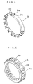
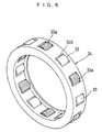
- Figs. 1 to 5 shows the best mode for carrying out the invention, wherein Fig. 1 is a vertical sectional view of a pulley unit according to a best mode for carrying out the present invention, Fig. 2 is a sectional view along a arrow of (2)-(2) in Fig. 1, Fig. 3 is a perspective view of a rotor shaft and a retainer of a one-way clutch in Fig. 1, Fig. 4 is a perspective view of a retainer of a ball bearing in Fig. 1 and Fig. 5 is a perspective view of a retainer of a roller bearing in Fig. 1.
- a pulley unit A includes a pulley 1, a rotor shaft 2, a one-way clutch 3, a ball bearing 4 and a roller bearing 5 as rolling bearings, and a seal ring 6.
- the hollow shaft 2 of the pulley unit A serves as an inner ring of each of the one-way clutch 3, the ball bearing 4 and the roller bearing 5.
- the pulley 1 of the pulley unit A serves as an outer ring of each of the one-way clutch 3, the ball bearing 4 and the roller bearing 5.
- the pulley 1 is rotated by a crankshaft of an automobile engine through a V-ribbed belt B.
- An outer periphery of the pulley 1 is formed with corrugated grooves around which the V-ribbed belt B is wound.
- An axially one end region of an inner diametrical surface of the pulley 1 is formed with an raceway groove in which balls 23 of the ball bearing 4 are interposed.
- the ball bearing 4 is a deep-slot ball bearing.
- the rotor shaft 2 is a hollow shaft body, and is concentrically disposed in an inner diameter side of the pulley 1 and in a relatively rotatable relationship with the pulley 1.
- the rotor shaft 2 is fixed to an input shaft (e.g., a rotor of an alternator) of an auxiliary machine of an automobile engine (not shown).
- a circumference of an axially intermediate region 2a is formed at its several portions with flat cam surfaces 10a of the one-way clutch 3.
- axially opposite side regions 2b and 2c are formed with inner ring raceways of the ball bearing 4 and the roller bearing 5.
- the region 2a of the rotor shaft 2 is formed into an octagon, and the opposite side regions 2b and 2c are formed circular.
- an outer diameter size of the region 2b which is an inner ring raceway of the ball bearing 4 is set larger than an outer diameter size of the region 2c which is an inner ring raceway of the roller bearing 5.
- the region 2b of the rotor shaft 2 is formed with an raceway groove in which the balls 23 of the ball bearing 4 is interposed.
- the region 2c of the rotor shaft 2 is formed with a peripheral groove 2d.
- a diametrically inward ring-like projection 34a is provided on an inner diametrical surface of the retainer 34 of the roller bearing 5.
- the ring-like projection 34a is engaged in the peripheral groove 2d of the rotor shaft 2.
- the one-way clutch 3 is interposed in substantially axial central portion of the opposed annular space between the inner diametrical surface of the pulley 1 and the outer diametrical surface of the rotor shaft 2.
- the inner ring raceway of the one-way clutch 3 is constituted by the outer diametrical surface of the rotor shaft 2, and the outer ring raceway of the one-way clutch 3 is constituted by an inner diametrical surface of the pulley 1.
- the one-way clutch 3 comprises annular-shaped retainer 12 made of synthetic resin, a plurality of rollers 13 as rolling elements, and oval coil springs 14 as resilient members.
- the retainer 12 is disposed in the annular space and is external mounted in a state of being located in the circumferential and axial directions therein.
- the retainer 12 includes a plurality of pockets 12a which pass through the retainer 12 from inside to outside corresponding to the cam surfaces 10a of the region 2a of the rotor shaft 2.
- An axial column 12b exists between the adjacent pockets 12a in the circumferential direction.
- rollers 13 of the one-way clutch 3 are accommodated in the pockets 12a of the retainer 12 one each in a state in which the rolling range in the circumferential direction is restrained.
- Each of the coil springs 14 of the one-way clutch 3 is mounted to a projection 12c projecting from an inner wall surface of each of the columns 12b of the retainer 12, and pushes the roller 13 toward a narrow side (look side) of a wedge-like space formed by a cam surface 10a and an inner diametrical surface of the pulley 1.
- the inner diametrical surface of the retainer 12 of the one-way clutch 3 is formed into a shape which coincides and fits to the octagonal outer diametrical surface of the axially intermediate region 2a of the rotor shaft 2. With this design, the retainer 12 is prevented from being rotated in the circumferential direction with respect to the rotor shaft 2.
- a tapered step 2e is mounted between the cam surface 10a of the intermediate region 2a and a large-diameter region 2b of the rotor shaft 2.
- the retainer 12 of the one-way clutch 3 is prevented from moving toward the ball bearing 4 by the step 2e.
- the retainer 12 is also prevented from moving toward the roller bearing 5 by a retainer 34 of the roller bearing 5 that is positioned to rotor shaft 2 in the axial direction.
- the ball bearing 4 and the roller bearing 5 are interposed one each on axially opposite sides of the one-way clutch 3 in opposed annular space of the inner diametrical surface of the pulley 1 and the outer diametrical surface of the rotor shaft 2.
- the inner ring raceway of the ball bearing 4 is constituted by the outer diametrical surface of the region 2b of the rotor shaft 2, and the outer ring raceway of the ball bearing 4 is constituted by the inner diametrical surface of the pulley 1.
- the ball bearing 4 is a general deep-slot ball bearing comprising a plurality of the balls 23 as rolling elements and a coronary retainer 24 for holding the balls 23.
- the retainer 24 of the ball bearing 4 is made of resin.
- the inner ring raceway of the roller bearing 5 is constituted by the outer diametrical surface of the region 2c of the rotor shaft 2, and the outer ring raceway of the roller bearing 5 is constituted by the inner diametrical surface of the pulley 1.
- the roller bearing 5 is a cage-and-roller comprising a plurality of rollers 33 as rolling elements and a retainer 34 for holding the rollers 33.
- the retainer 34 of the roller bearing 5 is made of resin.
- a seal ring 6 is mounted to axially outer ends of the ball bearing 4 and the roller bearing 5 in the annular space.
- the seal ring 6 is in a contact form, and an elastic body is mounted to an outer periphery of an annular core of the seal ring 6.
- One end of the elastic body of the seal ring 6 is fixed to the inner diametrical surface of the pulley 1, and the other end abuts against the outer diametrical surface of the rotor shaft 2 as a seal ring lip 6a.
- Various seal ring lips 6a exist other than the above type.
- the one-way clutch 3 is brought into the lock state or the free state in accordance with a difference in rotation speed between the pulley 1 and the rotor shaft 2 so as to transmit power from the pulley 1 to the rotor shaft 2 or to cut of the transmission of the power.
- the retainers 24 and 34 of the ball bearing 4 and the roller bearing 5 respectively have annular portions facing to the seal rings 6.
- the annular portions of the retainers 24 and 34 have outer diameter sides 24a and 34a reduced in diameter.
- the outer diameter sides 24a and 34a may be reduced in diameter over the entire circumference of the outer diametrical surfaces of the retainers 24 and 34, or may be reduced in diameter partially.
- the outer diameter side 24a is one or more notches or recesses with respect to the circumferential direction of the outer diametrical surface of the retainer 24, and the outer diameter side 34a is one or more recesses with respect to the outer diametrical surface of the retainer 34.
- a portion of a region of the inner diametrical surface of the pulley 1 between the axial directions of the one-way clutch 3 and the ball bearing 4 is provided with a recess 1a which increases the storage volume for the lubricating oil in the annular space.
- the recess 1a may be formed annularly over the entire periphery of the inner diametrical surface of the pulley 1, or may be one or more separated recesses.
- the storage space for the lubricating oil in the annular space between the pulley 1 and the rotor shaft 2 is increased by the outer diameter sides 24a and 34a and the recess 1a.
- the outer diameter sides 24a and 34a are provided outer ends of the retainers 24 and 34 opposed to each of the seal rings 6 in the axial direction.
- the outer diameter side 24a of the annular portion facing to the seal ring 6 is formed into a taper structure in which its diameter is gradually decreased toward axially outer end.
- an inner diameter side 24b of the annular portion facing to the seal ring 6 is formed into a taper structure in which its diameter is gradually increased toward axially outer end.
- the lubricating oil located on the inner diameter side between the seal ring 6 and the ball bearing 4 moves toward the outer diameter side of the annular space by the rotation centrifugal force caused by relative rotation between the pulley 1 and the rotor shaft 2.
- the lubricating oil moves in this manner, since the inner diameter side 24b on the inner diameter side of the retainer 24 of the ball bearing 4 is tapered toward the axially inner end, the lubricating oil is moved smoothly toward the outer diameter side along the taper surface of the inner diameter side 24b.
- the lubricating oil which moved in this manner is stored in the storage space smoothly by the taper structure of the outer diameter side 24a on the outer diameter side of the retainer 24 of the ball bearing 4.
- a reference number 24c represents a pocket which accommodates the balls 23.
- the lubricating oil is more effectively prevented from leaking from the seal ring 6, the environment in which the lubricating oil is prone to be deteriorated is eliminated, and its ability is enhanced.
- a seal ring lip 6a of the seal ring 6 on the region 2b is provided as a main seal ring lip extending toward the center along the diametrical direction.
- a seal ring lip diagonally extending inward of the ball bearing 4 from a root of the main seal ring lip 6a is provided as an auxiliary seal ring lip 6b.
- the illustrated opposing distance a between the inner diameter side 24b and the auxiliary seal ring lip 6b is preferably at least 0.6 mm.
- the lubricating oil can smoothly move from the annular gap between the tapered inner diameter side 24b and the auxiliary seal ring lip 6b, which is preferable.
- the main seal ring lip 6a enters a peripheral groove 2f provided in the region 2b in the outer diametrical surface of the rotor shaft 2.
- the sealing amount of the lubricating oil in the pulley unit A was increased by about 20% as compared with that of the prior art.
- the inner diametrical surface of the pulley 1 and the outer diametrical surface of the rotor shaft 2 respectively constitute the outer ring raceway and the inner ring raceway of each of the one-way clutch 3, the ball bearing 4 and the roller bearing 5.
- the present invention is not limited to such raceway structure.
- each of the one-way clutch 3, the ball bearing 4 and the roller bearing 5 may include independent outer ring and inner ring.
- the present invention is not limited to the diametrically-reduced structure of the outer diameter sides 24a and 34a of the retainers 24 and 34 of the ball bearing 4 and the roller bearing 5 in the above embodiment. The invention is applied to all pulley units having portions which are reduced in diameter by any method.
- one or more of the plurality of balls 23 accommodated in the pocket 24c of the retainer 24 of the ball bearing 4 are made of resin including lubricating oil.
- the lubricating oil may gradually ooze from the balls 23.
- the width of the lubricating oil storage space is limited by the outer diameter sides 24a and 34a, the lubricating oil is leaked slightly, and when there is tendency that the lubricating oil will be lacking in the long term, the shortage of the lubricating oil can preferably be avoided, and the ability of the pulley unit can preferably be enhanced.
- the number of balls 23 made of resin including the lubricating oil may be determined experimentally in accordance with the shortage state of the lubricating oil.
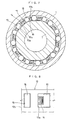
- the annular space is common for the one-way clutch 3, the ball bearing 4 and the roller bearing 5. Therefore, other than the structure in which the plurality of balls 23 accommodated in the pocket 24c of the retainer 24 of the ball bearing 4 are made of resin including lubricating oil, the rollers 33a made of resin including the lubricating oil may rollably be accommodated in one or more pockets 34b of the retainer 25 of the roller bearing 5 as shown in Fig. 6. In this case, this structure may be applied to only one side of or both sides of the ball bearing 4 and the roller bearing 5 experimentally in accordance with the shortage state of the lubricating oil.
- Pockets for accommodating lubricating oil impregnating bodies made of resin having lubricating oil may be provided in the retainer columns of the retainers 24 and 34 of the ball bearing 4 and the roller bearing 5.
- This lubricating oil impregnating body may be formed into a ball shape or a roller shape such that the body can roll.
- a pocket 15 for accommodating, in rolling manner, a lubricating oil impregnating body made of resin including lubricating oil is provided in the retainer column 12b of the retainer 12 of the one-way clutch 3 and the lubricating oil impregnating body 16 is accommodated in the pocket 15, the shortage of lubricating oil can effectively be eliminated and a preferable result can be obtained.
- This lubricating oil impregnating body 16 may be formed into a roller shape such that it can roll.
- the annular recess 1a for increasing the storage volume of the lubricating oil is provided, the lubricating oil impregnating body may be accommodated and held in the annular recess 1a.
- an annular recess 1b like the annular recess 1a may be provided in a region of the inner diametrical surface of the pulley 1 between the one-way clutch 3 and the roller bearing 5 in the axial direction, and lubricating oil impregnating bodies 1c and 1d may be accommodated and held in both the annular recesses 1a and 1b.
- This annular recess 1b is not limited to an annular shape, and may be a plurality of separately formed recesses.
- the resin including the lubricating oil in each of the one-way clutch 3 mentioned above, the ball bearing 4, the roller bearing 5 and the annular recesses 1a and 1b comprises a resin frame in which the lubricating oil is solidified so that the lubricating oil is oozed from the resin frame.
- this resin examples include ultra high molecular weight polyethylene, polypropylene, polymethyl pentene.
- the ultra high molecular weight polyethylene is superior in mechanical nature and thus, it can be used preferably.
- this ultra high molecular weight polyethylene one having average molecular mass of about 1,000,000 to 6,000,000, especially 2,000,000 or more and having melting point of about 100°C to 400°C is preferable.
- a particle diameter of the resin is not specially limited, but it is usually preferable that the average particle diameter is about 5 ⁇ m to 10 ⁇ m, and more preferably, about 10 ⁇ m to 30 ⁇ m.
- the conventionally known lubricating oil can be used, stable lubricating oil whose resin's mechanical nature is not deteriorated by heating when the resin is solidified can be preferably used.
- lubricating oil examples include mineral oil, poly- ⁇ -olefin oil, diester oil, holyall ester oil, alkyl diphenyl ether oil, silicone oil, paraffin oil, fluorine oil and the like.
- Various addition agents can be added to the lubricating oil so as to enhance characteristics such as lubricity, stability and the like.
- One or more of the lubricating oils described above can be used.
- the amount of the lubricating oil is set to 65 weight % to 20 weight % with respect to 35 weight % to 85 weight % of resin. In this amount, if more than 65 weight % lubricating oil is mixed, the lubricating oil keeping ability of the resin is relatively lowered, and if the less than 20 weight % of lubricating oil is mixed, the lubricating oil keeping ability becomes relatively large.
- At least one of the retainers 12, 24 and 34 of the one-way clutch 3, the ball bearing 4 and the roller bearing 5 may be made of resin having the lubricating oil.
- the resin and the lubricating oil may be made of mixture of the same resin and lubricating oil as those of (3) described above. (5) In the pulley unit mentioned above, studies for enhancing the seal ring ability of the seal ring 6 were made, and it found that if acrylic resin having excellent heat resistance is used instead of nitrile-butadiene rubber (NBR) which was generally used for the seal ring 6, the ability of the seal ring 6 could further be enhanced.
- NBR nitrile-butadiene rubber
- the present inventor used the acrylic resin having excellent heat resistance instead of the NBR, the thermosetting described above could be prevented from being generated in the seal ring 6, and the seal ring ability could be maintained or improved.
- the acrylic resin is most preferable, but the resin is not limited to this, and any resin having excellent heat resistance can prevent the thermosetting from being generated and can maintain the seal ring ability.
- the present invention is not limited to detailed structure of the one-way clutch 3, the ball bearing 4 and the roller bearing 5 in the above embodiment.
- the pulley unit of the present invention can be mounted to an auxiliary machine which is driven by a crankshaft of an engine of an automobile or the like through a belt.
- auxiliary machine examples include an air conditioner compressor of an automobile, a water pump, an alternator, a cooling fan and the like.
Landscapes
- Engineering & Computer Science (AREA)
- General Engineering & Computer Science (AREA)
- Mechanical Engineering (AREA)
- Pulleys (AREA)
- Rolling Contact Bearings (AREA)
- Sealing Of Bearings (AREA)
Abstract
Description
(2) The present invention is not limited to the diametrically-reduced structure of the
(3) In the case of the above pulley unit A, one or more of the plurality of
(4) In the case of the above embodiment, at least one of the
(5) In the pulley unit mentioned above, studies for enhancing the seal ring ability of the
(6) The present invention is not limited to detailed structure of the one-
Claims (21)
- A pulley unit comprising:wherein said inner diametrical surface of said pulley forms an outer ring raceway of each of said one-way clutch and said rolling bearing;a pulley;a shaft body concentrically disposed in an inner diameter side of said pulley and in a relatively rotatable relationship with said pulley;a one-way clutch interposed in an annular space between an inner diametrical surface of said pulley and an outer diametrical surface of said shaft body;a rolling bearing disposed in said annular space on at least axially one side of said one-way clutch; andseal rings disposed on each of axially one end and axially other end of said annular space for sealing said annular space;
said outer diametrical surface of said shaft body forms an inner ring raceway of each of said one-way clutch and said rolling bearing;
said one-way clutch and said rolling bearing each include a plurality of rolling elements interposed between said outer ring raceway and the inner ring raceway in the circumferential direction, and a retainer having a plurality of pockets each accommodating said rolling elements one each;
said retainer of said rolling bearing has an annular portion facing to the side of said seal ring, said annular portion having an outer diameter side which is reduced in diameter so as to increase a storage volume for lubricating oil between said rolling bearing and said seal ring. - A pulley unit according to claim 1, wherein said rolling bearing is a roller bearing comprising a retainer for holding rolling elements, said retainer having an annular portion facing to the side of said seal ring, said annular portion having an outer diameter side which is reduced in diameter.
- A pulley unit according to claim 1, wherein an inner diametrical surface of said pulley between said one-way clutch and said rolling bearing is provided with a recess which increases said storage volume for the lubricating oil in said annular space.
- A pulley unit according to claim 1, wherein said rolling bearing is a ball bearing comprising a retainer for holding rolling elements, which has an annular portion facing to the side of said seal ring, said annular portion having an inner diameter side tapered so as to gradually increase in diameter toward its axially outer end.
- A pulley unit according to claim 4, wherein in said retainer of said ball bearing, said annular portion facing to the side of the seal ring has an outer diameter side tapered so as to gradually decrease in diameter toward its axially outer end.
- A pulley unit according to claim 1, wherein at least one of said rolling elements of said rolling bearing is made of resin including lubricating oil.
- A pulley unit according to claim 3, further comprising a lubricating oil-impregnating body which is accommodated and held in said recess.
- A pulley unit comprising:wherein said inner diametrical surface of said pulley forms an outer ring raceway of each of said one-way clutch and said rolling bearing;a pulley;a shaft body concentrically disposed in an inner diameter side of said pulley and in a relatively rotatable relationship with said pulley;a one-way clutch interposed in an annular space between an inner diametrical surface of said pulley and an outer diametrical surface of said shaft body;a rolling bearing disposed in said annular space on at least axially one side of the one-way clutch and comprising a retainer for holding rolling elements; andseal rings disposed on each of axially one end and axially other end of said annular space for sealing said annular space;
said outer diametrical surface of said shaft body forms an inner ring raceway of each of said one-way clutch and said rolling bearing;
said one-way clutch and said rolling bearing each indlude a plurality of rolling elements interposed between said outer ring raceway and said inner ring raceway in the circumferential direction, and include a retainer having a plurality of pockets each accommodating said rolling elements one each; and
a recess for increasing a storage volume for lubricating oil in said annular space is provided in an inner diametrical surface of said pulley between said one-way clutch and said rolling bearing. - A pulley unit according to claim 8, wherein at least one of said rolling elements of said rolling bearing is made of resin including lubricating oil.
- A pulley unit according to claim 8, further comprising a lubricating oil impregnating body which is accommodated and held in said recess.
- A pulley unit comprising:wherein said inner diametrical surface of said pulley forms an outer ring raceway of each of said one-way clutch and said rolling bearings;a pulley;a shaft body concentrically disposed in an inner diameter side of said pulley and in a relatively rotatable relationship with said pulley;a one-way clutch interposed in an annular space between an inner diametrical surface of said pulley and an outer diametrical surface of said shaft body;rolling bearings disposed in said annular space on opposite sides of said one-way clutch; andseal rings disposed on each of axially one end and axially other end of said annular space for sealing said annular space;
said outer diametrical surface of said shaft body forms an inner ring raceway of each of said one-way clutch and said rolling bearings;
said one-way clutch and rolling bearings include a plurality of rolling elements interposed between said outer ring raceway and said inner ring raceway in the circumferential direction, and include a retainer having a plurality of pockets each accommodating said rolling elements one each;
said retainers of said rolling bearings each has an annular portion facing to the side of said seal ring, said annular portion having an outer diameter side reduced in diameter so as to increase a storage volume for lubricating oil between said seal ring opposing in an axial direction. - A pulley unit according to claim 11, wherein one of said rolling bearings is a roller bearing, said roller bearing having a retainer for holding rolling elements, said retainer of said roller bearing comprising an annular portion facing to the seal ring, said annular portion having an outer diameter side reduced in diameter.
- A pulley unit according to claim 11, wherein an inner diametrical surface of said pulley between said one-way clutch and at least one of said rolling bearings is provided with a recess which increases a storage volume of lubricating oil in said annular space.
- A pulley unit according to claim 11, wherein the other of said rolling bearings is a ball bearing comprising a retainer for holding rolling elements, said retainer including an annular portion facing to the side of said seal ring, said annular portion having an inner diameter side tapered so as to gradually increase in diameter toward its axially outer end.
- A pulley unit according to claim 14, wherein said annular portion of said retainer of said ball bearing has an outer diameter side tapered so as to gradually decrease in diameter toward its axially outer end.
- A pulley unit according to claim 13, furthr comprising a lubricating oil impregnating body which is accommodated and held in said recess.
- A pulley unit comprising:wherein an inner diametrical surface of said pulley forms an outer ring raceway of each of said one-way clutch, the ball bearing and the roller bearing;a pulley;a shaft body concentrically disposed in an inner diameter side of said pulley and in a relatively rotatable relationship with said pulley;a one-way clutch interposed in an annular space between an inner diametrical surface of said pulley and an outer diametrical surface of said shaft body;a ball bearing provided on axially one side of the one-way clutch in said annular space;a roller bearing provided on axially other side of the one-way clutch in said annular space;seal rings disposed on each of axially one end and axially other end of said annular space for sealing said annular space;
an outer diametrical surface of said shaft body forms an inner ring raceway of each of said one-way clutch, said ball bearing and said roller bearing;
said one-way clutch, said ball bearing and said roller bearing each include a plurality of rolling elements interposed between said outer ring raceway and said inner ring raceway in the circumferential direction, and include a retainer having a plurality of pockets each accommodating said rolling elements one each;
said retainers of said ball bearing and said roller bearing each have an annular portion facing to the side of said seal ring, said annular portion having an outer diameter side reduced in diameter so as to increase a storage volume for lubricating oil between said seal rings opposed to each other in their axial direction. - A pulley unit according to claim 17, wherein an inner diametrical surface of said pulley between said one-way clutch and the ball bearing is provided with a recess which increases the storage volume of the lubricating oil in said annular space.
- A pulley unit according to claim 18, further comprising a lubricating oil-impregnating body which is accommodated and held in said recess.
- A pulley unit according to claim 17, wherein said annular portion of said retainer of said ball bearing has an inner diameter side tapered so as to gradually increase in diameter toward its axially outer end and an outer diameter side tapered so as to gradually decrease in diameter toward its axially outer end.
- A pulley unit according to claim 17, wherein the outer diametrical surface of said shaft body includes an axially one region where said ball bearing is disposed, an axially intermediate region where said one-way clutch is disposed, and an axially other region where said roller bearing is disposed, each of said regions forms the inner ring raceway of each of the one-way clutch, the ball bearing and the roller bearing, an outer diameter of said axially one region where said ball bearing is disposed, is larger than an outer diameter of said axially other region where said roller bearing is disposed.
Applications Claiming Priority (5)
| Application Number | Priority Date | Filing Date | Title |
|---|---|---|---|
| JP2000226636 | 2000-07-27 | ||
| JP2000226636 | 2000-07-27 | ||
| JP2000390263A JP4244518B2 (en) | 2000-07-27 | 2000-12-22 | Pulley unit |
| JP2000390263 | 2000-12-22 | ||
| PCT/JP2001/006491 WO2002010617A1 (en) | 2000-07-27 | 2001-07-27 | Pulley unit |
Publications (3)
| Publication Number | Publication Date |
|---|---|
| EP1217259A1 true EP1217259A1 (en) | 2002-06-26 |
| EP1217259A4 EP1217259A4 (en) | 2006-08-30 |
| EP1217259B1 EP1217259B1 (en) | 2009-03-18 |
Family
ID=26596785
Family Applications (1)
| Application Number | Title | Priority Date | Filing Date |
|---|---|---|---|
| EP01984437A Expired - Lifetime EP1217259B1 (en) | 2000-07-27 | 2001-07-27 | Pulley unit |
Country Status (5)
| Country | Link |
|---|---|
| US (1) | US7056247B2 (en) |
| EP (1) | EP1217259B1 (en) |
| JP (1) | JP4244518B2 (en) |
| DE (1) | DE60138003D1 (en) |
| WO (1) | WO2002010617A1 (en) |
Cited By (1)
| Publication number | Priority date | Publication date | Assignee | Title |
|---|---|---|---|---|
| EP2886900A4 (en) * | 2012-08-20 | 2016-08-03 | Nsk Ltd | Roller clutch equipped with support bearing |
Families Citing this family (24)
| Publication number | Priority date | Publication date | Assignee | Title |
|---|---|---|---|---|
| US6588560B1 (en) * | 1999-11-19 | 2003-07-08 | Koyo Seiko Co., Ltd. | Pulley unit |
| US6830137B2 (en) * | 2001-05-24 | 2004-12-14 | Koyo Seiko Co., Ltd. | Pulley unit having one-way clutch |
| US6699149B1 (en) * | 2002-04-01 | 2004-03-02 | Brunswick Corporation | Idler pulley with a multiple position locating mechanism |
| JP4158556B2 (en) * | 2003-02-28 | 2008-10-01 | 株式会社ジェイテクト | Power transmission device |
| US6986344B2 (en) * | 2004-02-13 | 2006-01-17 | Electrolux Professional Outdoor Products, Inc | Bladeshaft assembly for a powered saw or cutting machine |
| JP4543882B2 (en) * | 2004-10-29 | 2010-09-15 | 株式会社ジェイテクト | One-way clutch |
| JP2006322596A (en) * | 2005-05-20 | 2006-11-30 | Ntn Corp | Bearing composite one-way clutch |
| EP1947370A1 (en) * | 2005-10-14 | 2008-07-23 | JTEKT Corporation | Pulley apparatus and auto-tensioner |
| FR2913081B1 (en) * | 2007-02-27 | 2009-05-15 | Skf Ab | DEBRAYABLE PULLEY DEVICE |
| US8944947B2 (en) * | 2008-03-26 | 2015-02-03 | Jtekt Corporation | Pulley unit |
| US8939044B2 (en) * | 2009-06-26 | 2015-01-27 | Ntn Corporation | Retainer made of synthetic resin for use in a deep groove ball bearing; deep groove ball bearing; and gear support device |
| US8908027B2 (en) | 2010-08-20 | 2014-12-09 | SeeScan, Inc. | Asymmetric drag force bearings for use with push-cable storage drums |
| US8733739B2 (en) * | 2011-03-21 | 2014-05-27 | Kirk Martin Mauthner | Device that integrates an ascender with a pulley block |
| WO2013077422A1 (en) * | 2011-11-25 | 2013-05-30 | 日本精工株式会社 | Rotating machine with pulley and built-in one-way clutch |
| US9121495B2 (en) | 2013-03-15 | 2015-09-01 | Dayco Ip Holdings, Llc | Accessory drive decoupler |
| FR3014157A1 (en) * | 2013-12-02 | 2015-06-05 | Skf Ab | DEBRAYABLE PULLEY DEVICE, ALTERNATOR COMPRISING SUCH A DEVICE AND INTERNAL COMBUSTION ENGINE EQUIPPED WITH SUCH A DEVICE OR SUCH ALTERNATOR |
| JP6256013B2 (en) * | 2014-01-09 | 2018-01-10 | 株式会社ジェイテクト | Pulley unit |
| TWI555932B (en) * | 2014-07-14 | 2016-11-01 | 勝利工業股份有限公司 | Pulley for an alternator |
| JP2017116060A (en) * | 2015-12-25 | 2017-06-29 | キヤノン株式会社 | One-way clutch and image forming apparatus |
| JP2018179234A (en) * | 2017-04-19 | 2018-11-15 | 株式会社ジェイテクト | Rolling bearing |
| CN107902579B (en) * | 2017-11-11 | 2023-06-23 | 华强方特(芜湖)文化科技有限公司 | Pulley protection device of stage single-point crane |
| US20190211912A1 (en) * | 2018-01-09 | 2019-07-11 | Alt America Inc. | Axial Driven Overrunning Alteration Pulleys |
| FR3079583B1 (en) * | 2018-04-03 | 2020-03-06 | Aktiebolaget Skf | PULLEY DEVICE FOR TENSIONER OR ROLLER |
| CN118149025B (en) * | 2024-05-10 | 2024-08-06 | 宁波东煌轴承有限公司 | One-way bearing |
Family Cites Families (21)
| Publication number | Priority date | Publication date | Assignee | Title |
|---|---|---|---|---|
| US1583276A (en) * | 1925-07-17 | 1926-05-04 | Brown Westgarth Stanho Forster | Pinion |
| US4073552A (en) * | 1973-07-17 | 1978-02-14 | Hughes Aircraft Company | Bearing retainer |
| IT8452936V0 (en) * | 1984-02-01 | 1984-02-01 | Riv Officine Di Villar Perosa | TRANSMISSION UNIT SUITABLE FOR TRANSMITTING THE MOTORCYCLE BY A DRIVE BELT FROM THE CRANKSHAFT OF A COMBUSTION ENGINE INTERNAL TO THE ENGINE ACCESSORIES |
| IT1258778B (en) * | 1992-01-16 | 1996-02-29 | FREE PIN WITH CONICAL ROLLING BODIES | |
| DE4322554A1 (en) * | 1993-07-07 | 1995-01-12 | Schaeffler Waelzlager Kg | Cam roller |
| JP3547489B2 (en) * | 1993-08-10 | 2004-07-28 | 光洋精工株式会社 | Cage for rolling bearing |
| JP3517268B2 (en) * | 1994-03-14 | 2004-04-12 | Ntn株式会社 | Cylindrical roller bearing |
| JPH07317807A (en) * | 1994-03-30 | 1995-12-08 | Ntn Corp | Pulley unit |
| US5515957A (en) * | 1994-09-08 | 1996-05-14 | Mcconaghy; Robert F. | Uni-directional transmission with positive engagement and disengagement features |
| DE9417045U1 (en) * | 1994-10-22 | 1994-12-15 | INA Wälzlager Schaeffler KG, 91074 Herzogenaurach | Device for damping torsional vibrations in a drive train |
| JP3344131B2 (en) * | 1994-12-16 | 2002-11-11 | 日本精工株式会社 | Self-lubricating linear guide device |
| JPH08270662A (en) * | 1995-02-03 | 1996-10-15 | Koyo Seiko Co Ltd | Seal device for bearing |
| JP3681811B2 (en) * | 1995-09-29 | 2005-08-10 | Ntn株式会社 | Roller bearing |
| JPH10213207A (en) * | 1996-11-29 | 1998-08-11 | Nippon Seiko Kk | Pulley with built-in roller clutch |
| JPH1182688A (en) * | 1997-09-04 | 1999-03-26 | Koyo Seiko Co Ltd | Pulley unit |
| JP3731702B2 (en) * | 1997-09-24 | 2006-01-05 | 光洋精工株式会社 | Pulley unit |
| JP2000130563A (en) * | 1998-10-28 | 2000-05-12 | Koyo Seiko Co Ltd | Pulley unit |
| JP2000297860A (en) * | 1999-02-12 | 2000-10-24 | Nsk Ltd | Pulley device with built-in roller clutch for alternator |
| JP2001004011A (en) * | 1999-06-21 | 2001-01-09 | Koyo Seiko Co Ltd | Pulley unit |
| JP3434244B2 (en) * | 1999-08-26 | 2003-08-04 | 株式会社椿本チエイン | Cylindrical roller bearing |
| JP4339475B2 (en) * | 1999-12-28 | 2009-10-07 | バンドー化学株式会社 | One-way clutch |
-
2000
- 2000-12-22 JP JP2000390263A patent/JP4244518B2/en not_active Expired - Fee Related
-
2001
- 2001-07-27 EP EP01984437A patent/EP1217259B1/en not_active Expired - Lifetime
- 2001-07-27 US US10/089,015 patent/US7056247B2/en not_active Expired - Lifetime
- 2001-07-27 DE DE60138003T patent/DE60138003D1/en not_active Expired - Lifetime
- 2001-07-27 WO PCT/JP2001/006491 patent/WO2002010617A1/en not_active Ceased
Cited By (1)
| Publication number | Priority date | Publication date | Assignee | Title |
|---|---|---|---|---|
| EP2886900A4 (en) * | 2012-08-20 | 2016-08-03 | Nsk Ltd | Roller clutch equipped with support bearing |
Also Published As
| Publication number | Publication date |
|---|---|
| EP1217259A4 (en) | 2006-08-30 |
| JP2002106686A (en) | 2002-04-10 |
| US20020134974A1 (en) | 2002-09-26 |
| EP1217259B1 (en) | 2009-03-18 |
| DE60138003D1 (en) | 2009-04-30 |
| US7056247B2 (en) | 2006-06-06 |
| WO2002010617A1 (en) | 2002-02-07 |
| JP4244518B2 (en) | 2009-03-25 |
Similar Documents
| Publication | Publication Date | Title |
|---|---|---|
| US7056247B2 (en) | Pulley unit | |
| EP2386772B1 (en) | Rolling bearing with internal lubrication | |
| EP1030074B1 (en) | One-way clutch | |
| KR100799792B1 (en) | Rotational transmission with built-in one-way clutch | |
| EP1275868B1 (en) | One-way clutch unit | |
| JP2004019722A (en) | Rolling bearing | |
| EP1898112B1 (en) | One-way clutch and power transmission apparatus | |
| US20010000285A1 (en) | Pulley unit | |
| US6749050B2 (en) | One-way clutch built-in type pulley device | |
| JPH1182688A (en) | Pulley unit | |
| JP2000130563A (en) | Pulley unit | |
| JP2005214259A (en) | Ball bearings and ball bearings for alternators | |
| JP2002130433A (en) | Rotary transmission with built-in one-way clutch | |
| JP3550199B2 (en) | Rolling bearing | |
| JP4111556B2 (en) | High speed pulley unit for engine auxiliary equipment | |
| JP2000320558A (en) | Synthetic resin cage for roller bearings | |
| JP2001090751A (en) | One-way clutch, and pulley unit using same | |
| JPH08200376A (en) | Cage for roller bearing | |
| WO2023149266A1 (en) | Ball bearing | |
| JP2000337405A5 (en) | ||
| JPH07253113A (en) | Cylindrical roller bearing | |
| JP2002188709A (en) | Pulley unit | |
| JP3731703B2 (en) | Pulley unit | |
| JP2008069974A (en) | Pulley device capable of disengagement | |
| JP3731704B2 (en) | Pulley unit |
Legal Events
| Date | Code | Title | Description |
|---|---|---|---|
| PUAI | Public reference made under article 153(3) epc to a published international application that has entered the european phase |
Free format text: ORIGINAL CODE: 0009012 |
|
| AK | Designated contracting states |
Kind code of ref document: A1 Designated state(s): AT BE CH CY DE DK ES FI FR GB GR IE IT LI LU MC NL PT SE TR |
|
| 17P | Request for examination filed |
Effective date: 20020614 |
|
| RBV | Designated contracting states (corrected) |
Designated state(s): DE FR GB IT |
|
| RAP1 | Party data changed (applicant data changed or rights of an application transferred) |
Owner name: JTEKT CORPORATION |
|
| A4 | Supplementary search report drawn up and despatched |
Effective date: 20060731 |
|
| 17Q | First examination report despatched |
Effective date: 20070419 |
|
| GRAP | Despatch of communication of intention to grant a patent |
Free format text: ORIGINAL CODE: EPIDOSNIGR1 |
|
| GRAS | Grant fee paid |
Free format text: ORIGINAL CODE: EPIDOSNIGR3 |
|
| GRAA | (expected) grant |
Free format text: ORIGINAL CODE: 0009210 |
|
| AK | Designated contracting states |
Kind code of ref document: B1 Designated state(s): DE FR GB IT |
|
| REG | Reference to a national code |
Ref country code: GB Ref legal event code: FG4D |
|
| REF | Corresponds to: |
Ref document number: 60138003 Country of ref document: DE Date of ref document: 20090430 Kind code of ref document: P |
|
| PLBE | No opposition filed within time limit |
Free format text: ORIGINAL CODE: 0009261 |
|
| STAA | Information on the status of an ep patent application or granted ep patent |
Free format text: STATUS: NO OPPOSITION FILED WITHIN TIME LIMIT |
|
| 26N | No opposition filed |
Effective date: 20091221 |
|
| GBPC | Gb: european patent ceased through non-payment of renewal fee |
Effective date: 20090727 |
|
| PG25 | Lapsed in a contracting state [announced via postgrant information from national office to epo] |
Ref country code: GB Free format text: LAPSE BECAUSE OF NON-PAYMENT OF DUE FEES Effective date: 20090727 |
|
| PG25 | Lapsed in a contracting state [announced via postgrant information from national office to epo] |
Ref country code: IT Free format text: LAPSE BECAUSE OF FAILURE TO SUBMIT A TRANSLATION OF THE DESCRIPTION OR TO PAY THE FEE WITHIN THE PRESCRIBED TIME-LIMIT Effective date: 20090318 |
|
| PGFP | Annual fee paid to national office [announced via postgrant information from national office to epo] |
Ref country code: FR Payment date: 20140708 Year of fee payment: 14 |
|
| REG | Reference to a national code |
Ref country code: FR Ref legal event code: ST Effective date: 20160331 |
|
| PG25 | Lapsed in a contracting state [announced via postgrant information from national office to epo] |
Ref country code: FR Free format text: LAPSE BECAUSE OF NON-PAYMENT OF DUE FEES Effective date: 20150731 |
|
| PGFP | Annual fee paid to national office [announced via postgrant information from national office to epo] |
Ref country code: DE Payment date: 20190716 Year of fee payment: 19 |
|
| REG | Reference to a national code |
Ref country code: DE Ref legal event code: R119 Ref document number: 60138003 Country of ref document: DE |
|
| PG25 | Lapsed in a contracting state [announced via postgrant information from national office to epo] |
Ref country code: DE Free format text: LAPSE BECAUSE OF NON-PAYMENT OF DUE FEES Effective date: 20210202 |