EP1217241A1 - Dispositif de synchronisation pour boite de vitesses mécanique - Google Patents
Dispositif de synchronisation pour boite de vitesses mécanique Download PDFInfo
- Publication number
- EP1217241A1 EP1217241A1 EP01403257A EP01403257A EP1217241A1 EP 1217241 A1 EP1217241 A1 EP 1217241A1 EP 01403257 A EP01403257 A EP 01403257A EP 01403257 A EP01403257 A EP 01403257A EP 1217241 A1 EP1217241 A1 EP 1217241A1
- Authority
- EP
- European Patent Office
- Prior art keywords
- dogs
- groove
- ring
- sleeve
- pinion
- Prior art date
- Legal status (The legal status is an assumption and is not a legal conclusion. Google has not performed a legal analysis and makes no representation as to the accuracy of the status listed.)
- Withdrawn
Links
- 241000282472 Canis lupus familiaris Species 0.000 claims abstract description 23
- 230000005540 biological transmission Effects 0.000 claims abstract description 21
- 230000035939 shock Effects 0.000 description 2
- 230000000386 athletic effect Effects 0.000 description 1
- 230000002238 attenuated effect Effects 0.000 description 1
- 238000006073 displacement reaction Methods 0.000 description 1
- 238000002513 implantation Methods 0.000 description 1
- 238000012986 modification Methods 0.000 description 1
- 230000004048 modification Effects 0.000 description 1
- 230000000717 retained effect Effects 0.000 description 1
Images


Classifications
-
- F—MECHANICAL ENGINEERING; LIGHTING; HEATING; WEAPONS; BLASTING
- F16—ENGINEERING ELEMENTS AND UNITS; GENERAL MEASURES FOR PRODUCING AND MAINTAINING EFFECTIVE FUNCTIONING OF MACHINES OR INSTALLATIONS; THERMAL INSULATION IN GENERAL
- F16D—COUPLINGS FOR TRANSMITTING ROTATION; CLUTCHES; BRAKES
- F16D23/00—Details of mechanically-actuated clutches not specific for one distinct type
- F16D23/02—Arrangements for synchronisation, also for power-operated clutches
- F16D23/04—Arrangements for synchronisation, also for power-operated clutches with an additional friction clutch
Definitions
- the invention relates to a synchronization device for mechanical gearbox with at least one transmission gear adapted to be mounted idly on a drive shaft and fitted on one of its faces with dogs uniformly distributed around its axis of symmetry, a sliding sleeve with internal grooves adapted to rotate-link said sleeve with the shaft and fitted on at least one of its faces with dogs distributed uniformly around its axis of symmetry and adapted to be rotated by the dogs of the transmission gear.
- the object of the present invention is therefore to propose a device of the type of that mentioned above which can be used in a gearbox for vehicles series automobiles.
- the device is characterized by the fact that the transmission pinion has at least one side wall arranged around its dogs and having a groove in which is disposed a ring of deformable material suitable for braking a side wall integral with the sleeve and arranged around the dogs of the latter.
- the transmission pinion has at least one side wall arranged around its dogs and having a groove in which is disposed a ring of deformable material suitable for braking a side wall integral with the sleeve and arranged around the dogs of the latter.
- the ring of deformable material has knocks which are inserted into the throat of the transmission gear. These tocs allow better ring holding.
- the device which has just been described is advantageously mounted on a shaft of a vehicle gearbox automobile.
- the synchronization device 1 is mounted on a first shaft drive (not shown) of a gearbox mechanical installed in a motor vehicle with character athletic.
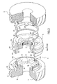
- This device 1 comprises two transmission gears 2,3 mounted crazy on the drive shaft and arranged on the side and on the other side of a sliding sleeve 4.
- Each of the pinions of transmission 2,3 is fitted on its side 21,31 opposite with sleeve 4 of a series of five dogs 22.32 distributed uniformly around their axis of symmetry.
- Each of these gears 2, 3 present, in a manner known per se, on its wall of revolution 23.33 adapted helical teeth 24.34 to mesh with another transmission gear relating to same report mounted on another drive shaft mounted parallel to the first.
- the wandering sleeve 4 has at its periphery a groove 40 in which the butt end of a fork is likely to come and stay, in a manner known per se, and whose displacement allows the approximation of the sleeve 4 towards one or the other of the transmission pinions 2.3. he also has on each of its lateral faces 41 a series of five dogs 42 of identical shape to those 22,32 of transmission gears 2,3 and internal splines 43 adapted to link the sleeve with the shaft in rotation drive.
- each transmission pinion 2,3 has a wall lateral 25.35 integral with it.
- This wall 25.35 is arranged around the dogs 22.32 and extends towards the exterior facing the player 4.
- Each of its walls 25.35 side has at its periphery a groove 26.36 in which is housed a ring 27.37 of deformable material which is retained via a stop clip 28.38.
- Each ring 27.37 has tabs 271.371 angularly distributed which are inserted into notches 251,351 made in the side wall 25.35 between two consecutive dogs 22.32.
- the player 4 has two side walls 43.44 arranged on either side of the groove 40 and which define respectively grooves 45,46 of shape combined with that of the side walls 25.35.
- the device according to the invention operates in the manner next.
- the side wall 25.35 opposite this pinion gradually rubs against the ring 27.37 until this area (F) is equal to the width of the Ring.
- the ring is compressed and rotates concomitantly with the walkman 4 according to the direction of rotation of the shaft on which it is mounted until the knocks 371 abut against the edge of the notches 351 corresponding.
- the differential speed of the sleeve player 4 is thus reduced and the shock during contact between the dogs 42 and those 32 of the pinion 3 is lessened.
- the noise generated outside the gearbox housing is like this much less than that generated by the device depending on the state of art ( Figure 1).
Landscapes
- Engineering & Computer Science (AREA)
- General Engineering & Computer Science (AREA)
- Mechanical Engineering (AREA)
- General Details Of Gearings (AREA)
- Structure Of Transmissions (AREA)
Abstract
Description
- un clip est monté dans la gorge du pignon et adapté pour bloquer la bague dans la gorge;
- la paroi latérale et le manchon baladeur sont une pièce monobloc;
- le manchon baladeur est muni sur ses deux faces de crabots répartis uniformément autour de son axe de symétrie et de deux parois latérales.
- la figure 1 est une vue éclatée en perspective d'un dispositif de synchronisation selon l'art antérieur,
- la figure 2 est une vue éclatée en perspective d'un dispositif de synchronisation représenté partiellement en coupe,
- la figure 3 une vue en perspective du dispositif selon la figure 2 représenté partiellement en coupe tel qu'il est monté sur un arbre de boite de vitesses.
Claims (6)
- Dispositif de synchronisation pour boite de vitesses mécanique (1) comportant au moins un pignon de transmission (2,3) adapté pour être monté fou sur un arbre d'entrainement et muni sur une de ses faces (21,31) de crabots (22,32) répartis uniformément autour de son axe de symétrie, un manchon baladeur (4) comportant des cannelures internes (41) adaptées pour lier à rotation ledit manchon avec l'arbre d'entrainement et muni sur au moins une de ses faces de crabots (42) répartis uniformément autour de son axe de symétrie et adaptés pour être entrainés en rotation par les crabots du pignon de transmission, caractérisé en ce que le pignon de transmission (2,3) comporte au moins une paroi latérale (25,35) disposée autour de ses crabots et présentant une gorge (26,36) dans laquelle est disposée une bague (27,37) en matériau déformable adaptée pour freiner une paroi latérale (43,44) solidaire du manchon et disposée autour des crabots de ce dernier.
- Dispositif selon la revendication 1, caractérisé en ce que la bague en matériau déformable comporte des tocs (371) qui viennent s'insérer dans la gorge du pignon de transmission.
- Dispositif selon la revendication 1 ou 2, caractérisé en ce qu'un clip (38) est monté dans la gorge du pignon et adapté pour bloquer la bague dans la gorge.
- Dispositif selon l'une des revendications précédentes, caractérisé en ce que la paroi latérale et le manchon baladeur sont une pièce monobloc.
- Dispositif selon l'une des revendications précédentes, caractérisé en ce que le manchon baladeur est muni sur ses deux faces de crabots répartis uniformément autour de son axe de symétrie et de deux parois latérales.
- Utilisation du dispositif selon l'une des revendications précédentes monté sur un arbre d'une boite de vitesses de véhicule automobile.
Applications Claiming Priority (2)
| Application Number | Priority Date | Filing Date | Title |
|---|---|---|---|
| FR0016893A FR2819299B1 (fr) | 2000-12-22 | 2000-12-22 | Dispositif de synchronisation pour boite de vitesses mecanique |
| FR0016893 | 2000-12-22 |
Publications (1)
| Publication Number | Publication Date |
|---|---|
| EP1217241A1 true EP1217241A1 (fr) | 2002-06-26 |
Family
ID=8858093
Family Applications (1)
| Application Number | Title | Priority Date | Filing Date |
|---|---|---|---|
| EP01403257A Withdrawn EP1217241A1 (fr) | 2000-12-22 | 2001-12-14 | Dispositif de synchronisation pour boite de vitesses mécanique |
Country Status (2)
| Country | Link |
|---|---|
| EP (1) | EP1217241A1 (fr) |
| FR (1) | FR2819299B1 (fr) |
Citations (2)
| Publication number | Priority date | Publication date | Assignee | Title |
|---|---|---|---|---|
| US2957564A (en) * | 1957-06-27 | 1960-10-25 | Renault | Gearbox synchromeshing devices |
| US3374870A (en) * | 1965-11-04 | 1968-03-26 | Int Harvester Co | Transmission synchronizer |
-
2000
- 2000-12-22 FR FR0016893A patent/FR2819299B1/fr not_active Expired - Fee Related
-
2001
- 2001-12-14 EP EP01403257A patent/EP1217241A1/fr not_active Withdrawn
Patent Citations (2)
| Publication number | Priority date | Publication date | Assignee | Title |
|---|---|---|---|---|
| US2957564A (en) * | 1957-06-27 | 1960-10-25 | Renault | Gearbox synchromeshing devices |
| US3374870A (en) * | 1965-11-04 | 1968-03-26 | Int Harvester Co | Transmission synchronizer |
Also Published As
| Publication number | Publication date |
|---|---|
| FR2819299A1 (fr) | 2002-07-12 |
| FR2819299B1 (fr) | 2003-02-28 |
Similar Documents
| Publication | Publication Date | Title |
|---|---|---|
| EP0948721B1 (fr) | Boite de vitesses avec marche arriere synchronisee pour vehicules automobiles | |
| WO2002075179A1 (fr) | Dispositif de transmission automatisee a transfert de couple, en particulier pour vehicule automobile | |
| EP2275719A1 (fr) | Boîte de vitesses comportant un moyen de blocage d'un arbre de sortie et véhicule comportant une telle boîte de vitesses | |
| WO2002099313A1 (fr) | Dispositif de verrouillage des pignons de transmission | |
| FR2467135A1 (fr) | Ensemble de pignons a plusieurs vitesses pour une bicyclette | |
| FR2487934A1 (fr) | Embrayage a griffes pour motocyclette | |
| FR2774447A1 (fr) | Vehicule equipe d'un dispositif de manoeuvre automatisee d'une boite a vitesses | |
| FR2924777A1 (fr) | Dispositif de commande interne de boite de vitesses | |
| EP1508728B1 (fr) | Dispositf de changement de vitesse, ensemble et véhicule automobile correspondants | |
| FR2806143A1 (fr) | Dispositif de transmission automatisee a transfert de couple, en particulier pour vehicule automobile | |
| FR2805020A1 (fr) | Boite de vitesses a freinage selectif d'arbre moteur et procede de mise en oeuvre | |
| FR2851022A1 (fr) | Dispositif de synchronisation pour boite de vitesses mecanique | |
| EP0819864B1 (fr) | Synchroniseur compact pour boíte de vitesses, notamment de véhicle automobile | |
| FR2819299A1 (fr) | Dispositif de synchronisation pour boite de vitesses mecanique | |
| WO2023198803A1 (fr) | Dispositif d'entraînement différentiel | |
| FR3136024A1 (fr) | Dispositif de couplage pour réducteur à deux rapports de vitesses | |
| EP1026417B1 (fr) | Ensemble synchroniseur pour une transmission d'un véhicule automobile | |
| EP1162380B1 (fr) | Ensemble synchroniseur pour une transmission de véhicule automobile | |
| EP0181824A1 (fr) | Mécanisme de synchronisation, en particulier pour boîte de vitesses; verrou élastique pour un tel mécanisme | |
| FR2540585A1 (fr) | Butee de debrayage en deux parties | |
| FR2709795A1 (fr) | Dispositif d'entraînement non permanent pour mécanisme réducteur de transmission. | |
| EP0300870B1 (fr) | Anneau presseur élastique pour mécanismes réducteurs multiplicateurs à au moins une sortie, destiné par exemple à la commande d'accessoires sur des véhicules | |
| EP2063154A1 (fr) | Dispositif de commande interne de boite de vitesses d'un vehicule automobile | |
| WO2023222782A1 (fr) | Dispositif de couplage pour reducteur a deux rapports de vitesses | |
| FR2783294A1 (fr) | Synchroniseur simple pour boite de vitesses notamment de vehicule automobile |
Legal Events
| Date | Code | Title | Description |
|---|---|---|---|
| PUAI | Public reference made under article 153(3) epc to a published international application that has entered the european phase |
Free format text: ORIGINAL CODE: 0009012 |
|
| AK | Designated contracting states |
Kind code of ref document: A1 Designated state(s): AT BE CH CY DE DK ES FI FR GB GR IE IT LI LU MC NL PT SE TR |
|
| AX | Request for extension of the european patent |
Free format text: AL;LT;LV;MK;RO;SI |
|
| 17P | Request for examination filed |
Effective date: 20020806 |
|
| AKX | Designation fees paid |
Designated state(s): CH DE ES GB IT LI |
|
| GRAP | Despatch of communication of intention to grant a patent |
Free format text: ORIGINAL CODE: EPIDOSNIGR1 |
|
| STAA | Information on the status of an ep patent application or granted ep patent |
Free format text: STATUS: THE APPLICATION IS DEEMED TO BE WITHDRAWN |
|
| 18D | Application deemed to be withdrawn |
Effective date: 20090911 |