EP1217173A2 - Vane for use in turbo machines - Google Patents
Vane for use in turbo machines Download PDFInfo
- Publication number
- EP1217173A2 EP1217173A2 EP01310161A EP01310161A EP1217173A2 EP 1217173 A2 EP1217173 A2 EP 1217173A2 EP 01310161 A EP01310161 A EP 01310161A EP 01310161 A EP01310161 A EP 01310161A EP 1217173 A2 EP1217173 A2 EP 1217173A2
- Authority
- EP
- European Patent Office
- Prior art keywords
- vane
- undercut
- transition zone
- vane according
- stress reducing
- Prior art date
- Legal status (The legal status is an assumption and is not a legal conclusion. Google has not performed a legal analysis and makes no representation as to the accuracy of the status listed.)
- Granted
Links
Images

Classifications
-
- F—MECHANICAL ENGINEERING; LIGHTING; HEATING; WEAPONS; BLASTING
- F01—MACHINES OR ENGINES IN GENERAL; ENGINE PLANTS IN GENERAL; STEAM ENGINES
- F01D—NON-POSITIVE DISPLACEMENT MACHINES OR ENGINES, e.g. STEAM TURBINES
- F01D17/00—Regulating or controlling by varying flow
- F01D17/10—Final actuators
- F01D17/12—Final actuators arranged in stator parts
- F01D17/14—Final actuators arranged in stator parts varying effective cross-sectional area of nozzles or guide conduits
- F01D17/16—Final actuators arranged in stator parts varying effective cross-sectional area of nozzles or guide conduits by means of nozzle vanes
- F01D17/165—Final actuators arranged in stator parts varying effective cross-sectional area of nozzles or guide conduits by means of nozzle vanes for radial flow, i.e. the vanes turning around axes which are essentially parallel to the rotor centre line
-
- F—MECHANICAL ENGINEERING; LIGHTING; HEATING; WEAPONS; BLASTING
- F01—MACHINES OR ENGINES IN GENERAL; ENGINE PLANTS IN GENERAL; STEAM ENGINES
- F01D—NON-POSITIVE DISPLACEMENT MACHINES OR ENGINES, e.g. STEAM TURBINES
- F01D17/00—Regulating or controlling by varying flow
- F01D17/10—Final actuators
- F01D17/12—Final actuators arranged in stator parts
- F01D17/14—Final actuators arranged in stator parts varying effective cross-sectional area of nozzles or guide conduits
- F01D17/16—Final actuators arranged in stator parts varying effective cross-sectional area of nozzles or guide conduits by means of nozzle vanes
-
- F—MECHANICAL ENGINEERING; LIGHTING; HEATING; WEAPONS; BLASTING
- F01—MACHINES OR ENGINES IN GENERAL; ENGINE PLANTS IN GENERAL; STEAM ENGINES
- F01D—NON-POSITIVE DISPLACEMENT MACHINES OR ENGINES, e.g. STEAM TURBINES
- F01D17/00—Regulating or controlling by varying flow
- F01D17/10—Final actuators
- F01D17/12—Final actuators arranged in stator parts
- F01D17/14—Final actuators arranged in stator parts varying effective cross-sectional area of nozzles or guide conduits
- F01D17/16—Final actuators arranged in stator parts varying effective cross-sectional area of nozzles or guide conduits by means of nozzle vanes
- F01D17/162—Final actuators arranged in stator parts varying effective cross-sectional area of nozzles or guide conduits by means of nozzle vanes for axial flow, i.e. the vanes turning around axes which are essentially perpendicular to the rotor centre line
-
- F—MECHANICAL ENGINEERING; LIGHTING; HEATING; WEAPONS; BLASTING
- F01—MACHINES OR ENGINES IN GENERAL; ENGINE PLANTS IN GENERAL; STEAM ENGINES
- F01D—NON-POSITIVE DISPLACEMENT MACHINES OR ENGINES, e.g. STEAM TURBINES
- F01D5/00—Blades; Blade-carrying members; Heating, heat-insulating, cooling or antivibration means on the blades or the members
- F01D5/12—Blades
- F01D5/14—Form or construction
- F01D5/147—Construction, i.e. structural features, e.g. of weight-saving hollow blades
Definitions
- Turbo machines such as gas turbine engines, have one or more turbine modules, each of which includes a plurality of blades and vanes for exchanging energy with the working medium fluid. Some of the vanes may be fixed and others may be variable, that is, rotatable between positions in the gas turbine engine.
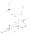
- a typical vane known in the prior art is shown in Figure 7 and comprises, generally, a trunnion portion (a) and an airfoil portion (b).
- the airfoil portion comprises a leading edge (d) and a trailing edge (e).
- the trunnion portion (a) has an enlarged button portion (f) proximate to a transition zone (g) between the trunnion and airfoil.
- the variable vane in operation is mounted for rotation about axis (c) so as to locate the position of the leading edge of the airfoil as desired. Generally, the variable vane is rotated through an angle of about 40°.
- variable vanes of a gas turbine engine operate in a hostile environment, they are subjected to significant stresses, both steady stress and vibratory stress.
- the design of variable vanes of the prior art are such that the transition zone (g) from the trunnion portion (a stiff section of the variable vane) to the airfoil portion of the vane (a flexible section of the variable vane) is subjected to high stresses which may lead to failure of the vane at the transition area and subsequent catastrophic damage to the gas turbine engine.
- the vane is provided with a stress reducing undercut on the stiff portion (trunnion portion) of the vane approximate to the transition zone between the stiff portion and the flexible portion (airfoil portion) of the vane.
- the undercut reduces stress in the area of the transition zone between the stiff and flexible portions of the vane.
- the actual vane design is determined by the function of the vane in the engine. Consequently, the stress reducing undercut geometry is such as to optimize the stress reduction in the transition zone for any particular vane design and function in a gas turbine engine.
- the width, radius of curvature, depth, location from the transition zone and sidewall angles of the stress reducing undercut is parametrically adjusted so as to minimize stress at the transition zone between the stiff section and the flexible section of the vane.
- a plurality of stress reducing undercuts may be provided on the stiff section of the vane proximate to the transition zone defined by the junction of the stiff section and the flexible section. If the vane is provided with trunnion portions on either side of the airfoil, stress reducing undercuts may be provided on one or both trunnion portions of the vane in an area proximate to the respective transition zones between the trunnion portions and the airfoil. In addition, one or more enlarged portions (buttons) may be provided on one or more of the trunnions adjacent the transition zones for receiving the undercuts.
- the design of the vane in accordance with the present invention offers a number of benefits. Firstly, the provision of stress reducing undercuts, which allow for smooth and continuous reduction in stress at the transition zones of the vane, greatly reduces the need for thickened airfoils which are typically used to reduce the stresses at the transition zones. Thus, there is a weight savings in the vane design. Secondly, the design allows for the vane to be cast rather than forged as is currently the case which results in substantial cost savings in manufacture.
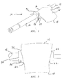
- Vane design of Figure 1 is an improvement over the prior art vane design illustrated in Figure 7.
- Vane 10 of Figure 1 includes a trunnion portion 12 and an airfoil portion 14.
- the airfoil portion 14 has a leading edge 16 and a trailing edge 18.
- the trunnion portion further includes an enlarged button portion 20 on one or both sides of the airfoil 14 proximate to the transition zones 22 between the trunnion portion and the airfoil portion.
- the trunnion portion 12 is provided with at least one stress reducing undercut 24 on the trunnion portion proximate to at least one of the transition zones 22. It has been found, in accordance with the present invention, that by providing a stress reducing undercut proximate to a transition zone, a substantially smooth and continuous reduction in stress is realized across the transition zone from the trunnion portion of the vane to the airfoil portion of the vane.
- the stress reducing undercut geometry is such as to optimize the stress reduction in a substantially smooth and continuous manner in the transition zone for a particular vane design and function in a gas turbine engine.
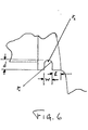
- the width w, radius of curvature from the sidewall, to the bottom wall r 1 and of the bottom wall r 2 , the depth d, the location 1 relative to the transition zones, and the sidewall angles ⁇ of the stress reducing undercut are parametrically adjusted so as to minimize stress at the transition zone between the stiff section (the trunnion portion) and the flexible section (the airfoil portion) of the vane. It is important, that the bottom wall of the stress reducing undercut have a radius of curvature r 2 and that the transition from the sidewalls of the undercut to the bottom wall also exhibit a radius of curvature r 1 . A sharp angle from the sidewalls to the bottom wall of the undercut groove would result in stress concentrations which would be undesirable.
- the side walls of the undercut may be substantially parallel or may diverge to form an angle.
- a plurality of stress reducing undercuts 24, 24' may be required, depending on vane defining function, in order to provide the substantial smooth and continuous reduction in stress at the transition zone.
- the undercuts are preferably of different depth and arranged serially on the trunnion portion with the first undercut 24' of a depth greater than the second undercut 24 being located between the second undercut 24 and the transition zone 22 as shown in Figure 3.
- the arrangement of the plurality of stress reducing undercuts as illustrated in Figure 3 is effective for some vane design geometries.
- the number of stress reducing undercuts and their geometry, vis-à-vis with radius', depths, locations and sidewall angles are such as to minimize stress at the transition zones 22.
- stress reducing undercuts may be provided on both sides of the airfoil illustrated in Figures 1-3 proximate to the respective transition zones.
- Figures 4 and 5 illustrate a second embodiment of vane design in accordance with the present invention.
- a stress reducing undercut 44 is provided on the trunnion portion 42 proximate to the transition zone 48 between the trunnion portion 42 and the airfoil portion 46 of the vane 40.
- the vane design of Figures 4 and 5 does not include an enlarged button portion as illustrated in Figures 1-3.
- the stress reducing undercut be located on the trunnion portion at a location remote from the leading edge of the airfoil and sized so as to ensure that the stress reducing undercut not be exposed to the air passing over the airfoil as the variable vane is rotated through the operational angle of between 30 to 50°.
- the foregoing is important so as to ensure proper operation of the vanes by avoiding a preferential path of air flow from the leading edge through the stress reducing undercut. Accordingly, the stress reducing undercut is located closer to the trailing edge of the airfoil then the leading edge on the trunnion portion.
- the design of the vane in accordance with the present invention offers a number of benefits. Firstly, the provision of a stress reduced undercut which allows for a smooth and continuous reduction in stress across the transition zone of the vane between the trunnion portion and the airfoil portion, greatly reduces the need for thickened airfoils which are typically used to reduce stresses at the transition zones in the prior art vane design. Accordingly, the life of the vane is greatly increased and the likelihood of catastrophic failure is decreased. By avoiding a thickened airfoil, there is an overall weight savings in the vane design of the present invention which is desirable. Secondly, the vane design of the present invention allows for the vane to be cast rather than forged as is currently required in the prior art. The castings are far less costly than forgings, and, consequently, substantial cost savings in manufacturing of the vane are realized.
Landscapes
- Engineering & Computer Science (AREA)
- Mechanical Engineering (AREA)
- General Engineering & Computer Science (AREA)
- Architecture (AREA)
- Turbine Rotor Nozzle Sealing (AREA)
- Control Of Turbines (AREA)
Abstract
Description
Claims (14)
- A vane (10; 40) comprising:a trunnion portion (12; 42);an airfoil portion (14; 46) connected to the trunnion portion at a location defining a transition zone (22; 48); anda stress reducing undercut (24; 44) on the trunnion portion (12; 42) and proximate to the transition zone (22; 48) so as to provide a substantially smooth and continuous reduction in stress at the transition zone (22; 48) from the trunnion portion (12; 42) to the airfoil portion (14; 46).
- A vane according to claim 1 wherein the trunnion portion (12) includes a shaft portion and an enlarged button portion (20) proximate to the transition zone (22), the stress reducing undercut (24) being located on the button portion (20).
- A vane according to claim 1 or 2 wherein the airfoil has a leading edge (16) and a trailing edge (18) and the stress reducing undercut (24; 44) is located closer to the trailing edge (18) than the leading edge (16).
- A vane according to any preceding claim wherein the stress reducing undercut (24; 44) is a groove defined by sidewalls and a bottom wall connected to the sidewalls by arcuate transitions having a radius of curvature (r1).
- A vane according to claim 4 wherein the bottom wall has a radius of curvature (r2).
- A vane according to claim 4 or 5 wherein the sidewalls are substantially parallel.
- A vane according to claim 4 or 5 wherein the sidewalls radiate from the bottom wall in a diverging manner to form an angle.
- A vane according to any preceding claim wherein the stress reducing undercut (24; 44) has a width, depth and location from the transition zone (22; 48) which is dependent on the design and function of the vane (10).
- A vane according to any preceding claim wherein the vane (10) is used in a turbomachine.
- A vane according to claim 9 wherein the vane (10) is used in a gas turbine engine.
- A vane according to any preceding claim wherein the trunnion portion (12) is provided with a plurality of stress reducing undercuts (24, 24').
- A vane according to claim 11 wherein the plurality of stress reducing undercuts (24, 24') comprises at least two undercuts of different depth arranged serially on the trunnion portion (12).
- A vane according to claim 12 wherein the first undercut (24') is of a depth greater than the second undercut (24) and the first undercut (24') is between the second undercut (24) and the transition zone (22).
- A vane according to any preceding claim wherein the vane (10) is formed by casting metal.
Applications Claiming Priority (2)
| Application Number | Priority Date | Filing Date | Title |
|---|---|---|---|
| US09/742,934 US6435821B1 (en) | 2000-12-20 | 2000-12-20 | Variable vane for use in turbo machines |
| US742934 | 2000-12-20 |
Publications (4)
| Publication Number | Publication Date |
|---|---|
| EP1217173A2 true EP1217173A2 (en) | 2002-06-26 |
| EP1217173A3 EP1217173A3 (en) | 2003-10-29 |
| EP1217173B1 EP1217173B1 (en) | 2006-04-19 |
| EP1217173B2 EP1217173B2 (en) | 2009-01-07 |
Family
ID=24986836
Family Applications (1)
| Application Number | Title | Priority Date | Filing Date |
|---|---|---|---|
| EP01310161A Expired - Lifetime EP1217173B2 (en) | 2000-12-20 | 2001-12-05 | Vane for use in turbo machines |
Country Status (4)
| Country | Link |
|---|---|
| US (1) | US6435821B1 (en) |
| EP (1) | EP1217173B2 (en) |
| JP (1) | JP3649691B2 (en) |
| DE (1) | DE60118868T3 (en) |
Cited By (5)
| Publication number | Priority date | Publication date | Assignee | Title |
|---|---|---|---|---|
| EP1918529A3 (en) * | 2006-11-03 | 2010-05-12 | Rolls-Royce Deutschland Ltd & Co KG | Turbomachine with adjustable stator vanes |
| EP2631435A1 (en) * | 2007-04-10 | 2013-08-28 | United Technologies Corporation | Turbine engine variable stator vane |
| EP2834471A4 (en) * | 2012-04-03 | 2016-06-01 | United Technologies Corp | DAMPING OF INDOOR VARIABLE BLADE PLATFORM |
| EP3623581A1 (en) * | 2018-09-14 | 2020-03-18 | United Technologies Corporation | Integral half vane, ringcase, and id shroud |
| US10794200B2 (en) | 2018-09-14 | 2020-10-06 | United Technologies Corporation | Integral half vane, ringcase, and id shroud |
Families Citing this family (11)
| Publication number | Priority date | Publication date | Assignee | Title |
|---|---|---|---|---|
| US7255530B2 (en) * | 2003-12-12 | 2007-08-14 | Honeywell International Inc. | Vane and throat shaping |
| US8240983B2 (en) * | 2007-10-22 | 2012-08-14 | United Technologies Corp. | Gas turbine engine systems involving gear-driven variable vanes |
| CH699998A1 (en) * | 2008-11-26 | 2010-05-31 | Alstom Technology Ltd | Guide vane for a gas turbine. |
| US8123471B2 (en) * | 2009-03-11 | 2012-02-28 | General Electric Company | Variable stator vane contoured button |
| SG166033A1 (en) * | 2009-05-08 | 2010-11-29 | Pratt & Whitney Services Pte Ltd | Method of electrical discharge surface repair of a variable vane trunnion |
| US20140064955A1 (en) * | 2011-09-14 | 2014-03-06 | General Electric Company | Guide vane assembly for a gas turbine engine |
| EP2738356B1 (en) * | 2012-11-29 | 2019-05-01 | Safran Aero Boosters SA | Vane of a turbomachine, vane assembly of a turbomachine, and corresponding assembly method |
| EP3019715B1 (en) | 2013-07-12 | 2020-01-15 | United Technologies Corporation | Method to repair variable vanes |
| US9784285B2 (en) | 2014-09-12 | 2017-10-10 | Honeywell International Inc. | Variable stator vane assemblies and variable stator vanes thereof having a locally swept leading edge and methods for minimizing endwall leakage therewith |
| US10287902B2 (en) | 2016-01-06 | 2019-05-14 | General Electric Company | Variable stator vane undercut button |
| CN113623021B (en) * | 2021-07-30 | 2023-01-17 | 中国航发沈阳发动机研究所 | Variable-geometry low-pressure turbine guide vane |
Family Cites Families (6)
| Publication number | Priority date | Publication date | Assignee | Title |
|---|---|---|---|---|
| CH488939A (en) * | 1968-03-26 | 1970-04-15 | Sulzer Ag | Bucket for turbo machinery |
| FR2030895A5 (en) * | 1969-05-23 | 1970-11-13 | Motoren Turbinen Union | |
| GB2151309B (en) * | 1983-12-15 | 1987-10-21 | Gen Electric | Variable turbine nozzle guide vane support |
| US5205714A (en) * | 1990-07-30 | 1993-04-27 | General Electric Company | Aircraft fan blade damping apparatus |
| GB2278647B (en) * | 1990-12-27 | 1995-04-05 | Snecma | Method of fixing flow-straightening blades in a turboshaft engine |
| GB2339244B (en) * | 1998-06-19 | 2002-12-18 | Rolls Royce Plc | A variable camber vane |
-
2000
- 2000-12-20 US US09/742,934 patent/US6435821B1/en not_active Expired - Lifetime
-
2001
- 2001-12-05 DE DE60118868T patent/DE60118868T3/en not_active Expired - Lifetime
- 2001-12-05 EP EP01310161A patent/EP1217173B2/en not_active Expired - Lifetime
- 2001-12-20 JP JP2001387919A patent/JP3649691B2/en not_active Expired - Fee Related
Cited By (6)
| Publication number | Priority date | Publication date | Assignee | Title |
|---|---|---|---|---|
| EP1918529A3 (en) * | 2006-11-03 | 2010-05-12 | Rolls-Royce Deutschland Ltd & Co KG | Turbomachine with adjustable stator vanes |
| EP2631435A1 (en) * | 2007-04-10 | 2013-08-28 | United Technologies Corporation | Turbine engine variable stator vane |
| EP2834471A4 (en) * | 2012-04-03 | 2016-06-01 | United Technologies Corp | DAMPING OF INDOOR VARIABLE BLADE PLATFORM |
| EP3623581A1 (en) * | 2018-09-14 | 2020-03-18 | United Technologies Corporation | Integral half vane, ringcase, and id shroud |
| US10781707B2 (en) | 2018-09-14 | 2020-09-22 | United Technologies Corporation | Integral half vane, ringcase, and id shroud |
| US10794200B2 (en) | 2018-09-14 | 2020-10-06 | United Technologies Corporation | Integral half vane, ringcase, and id shroud |
Also Published As
| Publication number | Publication date |
|---|---|
| US6435821B1 (en) | 2002-08-20 |
| US20020076321A1 (en) | 2002-06-20 |
| EP1217173B2 (en) | 2009-01-07 |
| EP1217173B1 (en) | 2006-04-19 |
| JP3649691B2 (en) | 2005-05-18 |
| DE60118868D1 (en) | 2006-05-24 |
| DE60118868T3 (en) | 2009-07-09 |
| EP1217173A3 (en) | 2003-10-29 |
| DE60118868T2 (en) | 2006-09-14 |
| JP2002227605A (en) | 2002-08-14 |
Similar Documents
| Publication | Publication Date | Title |
|---|---|---|
| EP1217173B1 (en) | Vane for use in turbo machines | |
| US6461105B1 (en) | Variable vane for use in turbo machines | |
| EP2154333B1 (en) | Airfoil and corresponding turbine assembly | |
| JP4805562B2 (en) | Turbine rotor blades for gas turbine engines | |
| US6602049B2 (en) | Compressor stator having a constant clearance | |
| KR100831803B1 (en) | Turbine Blade Pocket Shroud | |
| EP1762701B1 (en) | Skewed tip hole turbine blade | |
| EP1700007B1 (en) | Vane and throat shaping for a radial turbine assembly | |
| EP1918521B1 (en) | Compressor stator vane with variable pitch having an extended fillet | |
| EP1762702B1 (en) | Turbine blade | |
| US6916021B2 (en) | Sealing arrangement | |
| EP1057972A2 (en) | Turbine blade tip with offset squealer | |
| EP1231358A2 (en) | Airfoil shape for a turbine nozzle | |
| EP1270872B1 (en) | Gas turbine engine | |
| US7160084B2 (en) | Blade of a turbine | |
| EP1219778A2 (en) | Gas turbine blade with platform undercut | |
| US8052395B2 (en) | Air cooled bucket for a turbine | |
| EP1225305A2 (en) | Gas turbine shroud segment | |
| EP1375826B1 (en) | Radial turbine with guide vanes for reducing vibrations | |
| EP1561904B1 (en) | Turbine blade with cutting edges on tip shroud | |
| JP2008095695A (en) | Movable blade for turbomachine | |
| KR100486055B1 (en) | Cooling duct turn geometry for bowed airfoil | |
| JPS6365811B2 (en) | ||
| EP1601860B1 (en) | Turbine nozzle airfoil | |
| EP1106280A1 (en) | Core to control turbine bucket wall thickness and method |
Legal Events
| Date | Code | Title | Description |
|---|---|---|---|
| PUAI | Public reference made under article 153(3) epc to a published international application that has entered the european phase |
Free format text: ORIGINAL CODE: 0009012 |
|
| AK | Designated contracting states |
Kind code of ref document: A2 Designated state(s): AT BE CH CY DE DK ES FI FR GB GR IE IT LI LU MC NL PT SE TR |
|
| AX | Request for extension of the european patent |
Free format text: AL;LT;LV;MK;RO;SI |
|
| PUAL | Search report despatched |
Free format text: ORIGINAL CODE: 0009013 |
|
| AK | Designated contracting states |
Kind code of ref document: A3 Designated state(s): AT BE CH CY DE DK ES FI FR GB GR IE IT LI LU MC NL PT SE TR |
|
| AX | Request for extension of the european patent |
Extension state: AL LT LV MK RO SI |
|
| 17P | Request for examination filed |
Effective date: 20031202 |
|
| 17Q | First examination report despatched |
Effective date: 20040303 |
|
| AKX | Designation fees paid |
Designated state(s): DE FR GB |
|
| GRAP | Despatch of communication of intention to grant a patent |
Free format text: ORIGINAL CODE: EPIDOSNIGR1 |
|
| GRAS | Grant fee paid |
Free format text: ORIGINAL CODE: EPIDOSNIGR3 |
|
| GRAA | (expected) grant |
Free format text: ORIGINAL CODE: 0009210 |
|
| AK | Designated contracting states |
Kind code of ref document: B1 Designated state(s): DE FR GB |
|
| REG | Reference to a national code |
Ref country code: GB Ref legal event code: FG4D |
|
| REF | Corresponds to: |
Ref document number: 60118868 Country of ref document: DE Date of ref document: 20060524 Kind code of ref document: P |
|
| ET | Fr: translation filed | ||
| PLBI | Opposition filed |
Free format text: ORIGINAL CODE: 0009260 |
|
| PLAX | Notice of opposition and request to file observation + time limit sent |
Free format text: ORIGINAL CODE: EPIDOSNOBS2 |
|
| 26 | Opposition filed |
Opponent name: SIEMENS, AKTIENGESELLSCHAFT Effective date: 20070119 |
|
| PLAF | Information modified related to communication of a notice of opposition and request to file observations + time limit |
Free format text: ORIGINAL CODE: EPIDOSCOBS2 |
|
| PLBB | Reply of patent proprietor to notice(s) of opposition received |
Free format text: ORIGINAL CODE: EPIDOSNOBS3 |
|
| PUAH | Patent maintained in amended form |
Free format text: ORIGINAL CODE: 0009272 |
|
| STAA | Information on the status of an ep patent application or granted ep patent |
Free format text: STATUS: PATENT MAINTAINED AS AMENDED |
|
| 27A | Patent maintained in amended form |
Effective date: 20090107 |
|
| AK | Designated contracting states |
Kind code of ref document: B2 Designated state(s): DE FR GB |
|
| PGFP | Annual fee paid to national office [announced via postgrant information from national office to epo] |
Ref country code: FR Payment date: 20081205 Year of fee payment: 8 |
|
| REG | Reference to a national code |
Ref country code: FR Ref legal event code: ST Effective date: 20110729 |
|
| PG25 | Lapsed in a contracting state [announced via postgrant information from national office to epo] |
Ref country code: FR Free format text: LAPSE BECAUSE OF NON-PAYMENT OF DUE FEES Effective date: 20091231 |
|
| REG | Reference to a national code |
Ref country code: DE Ref legal event code: R082 Ref document number: 60118868 Country of ref document: DE Representative=s name: SCHMITT-NILSON SCHRAUD WAIBEL WOHLFROM PATENTA, DE |
|
| REG | Reference to a national code |
Ref country code: DE Ref legal event code: R082 Ref document number: 60118868 Country of ref document: DE Representative=s name: SCHMITT-NILSON SCHRAUD WAIBEL WOHLFROM PATENTA, DE Ref country code: DE Ref legal event code: R081 Ref document number: 60118868 Country of ref document: DE Owner name: UNITED TECHNOLOGIES CORP. (N.D.GES.D. STAATES , US Free format text: FORMER OWNER: UNITED TECHNOLOGIES CORP., HARTFORD, CONN., US |
|
| PGFP | Annual fee paid to national office [announced via postgrant information from national office to epo] |
Ref country code: DE Payment date: 20191119 Year of fee payment: 19 |
|
| PGFP | Annual fee paid to national office [announced via postgrant information from national office to epo] |
Ref country code: GB Payment date: 20191122 Year of fee payment: 19 |
|
| REG | Reference to a national code |
Ref country code: DE Ref legal event code: R119 Ref document number: 60118868 Country of ref document: DE |
|
| GBPC | Gb: european patent ceased through non-payment of renewal fee |
Effective date: 20201205 |
|
| PG25 | Lapsed in a contracting state [announced via postgrant information from national office to epo] |
Ref country code: DE Free format text: LAPSE BECAUSE OF NON-PAYMENT OF DUE FEES Effective date: 20210701 Ref country code: GB Free format text: LAPSE BECAUSE OF NON-PAYMENT OF DUE FEES Effective date: 20201205 |