EP1216834A2 - Ink jet printing using drop-on-demand techniques for continuous tone printing - Google Patents
Ink jet printing using drop-on-demand techniques for continuous tone printing Download PDFInfo
- Publication number
- EP1216834A2 EP1216834A2 EP20010204640 EP01204640A EP1216834A2 EP 1216834 A2 EP1216834 A2 EP 1216834A2 EP 20010204640 EP20010204640 EP 20010204640 EP 01204640 A EP01204640 A EP 01204640A EP 1216834 A2 EP1216834 A2 EP 1216834A2
- Authority
- EP
- European Patent Office
- Prior art keywords
- ink
- nozzle bore
- heater
- drop
- nozzle
- Prior art date
- Legal status (The legal status is an assumption and is not a legal conclusion. Google has not performed a legal analysis and makes no representation as to the accuracy of the status listed.)
- Granted
Links
- 238000007639 printing Methods 0.000 title description 6
- 238000007641 inkjet printing Methods 0.000 title description 4
- 238000000034 method Methods 0.000 title description 4
- 230000005499 meniscus Effects 0.000 claims abstract description 13
- 230000004913 activation Effects 0.000 claims abstract description 4
- 230000009467 reduction Effects 0.000 claims abstract description 4
- 230000003213 activating effect Effects 0.000 claims 1
- 239000000976 ink Substances 0.000 description 49
- 239000012530 fluid Substances 0.000 description 10
- XUIMIQQOPSSXEZ-UHFFFAOYSA-N Silicon Chemical compound [Si] XUIMIQQOPSSXEZ-UHFFFAOYSA-N 0.000 description 4
- 229910052710 silicon Inorganic materials 0.000 description 4
- 239000010703 silicon Substances 0.000 description 4
- 239000000758 substrate Substances 0.000 description 4
- 230000015572 biosynthetic process Effects 0.000 description 3
- 238000005516 engineering process Methods 0.000 description 3
- 230000007246 mechanism Effects 0.000 description 3
- 238000004064 recycling Methods 0.000 description 2
- 238000000347 anisotropic wet etching Methods 0.000 description 1
- 230000008859 change Effects 0.000 description 1
- 238000011109 contamination Methods 0.000 description 1
- 238000004519 manufacturing process Methods 0.000 description 1
- 230000004044 response Effects 0.000 description 1
- 238000000926 separation method Methods 0.000 description 1
- 230000001960 triggered effect Effects 0.000 description 1
- XLYOFNOQVPJJNP-UHFFFAOYSA-N water Substances O XLYOFNOQVPJJNP-UHFFFAOYSA-N 0.000 description 1
Images




Classifications
-
- B—PERFORMING OPERATIONS; TRANSPORTING
- B41—PRINTING; LINING MACHINES; TYPEWRITERS; STAMPS
- B41J—TYPEWRITERS; SELECTIVE PRINTING MECHANISMS, i.e. MECHANISMS PRINTING OTHERWISE THAN FROM A FORME; CORRECTION OF TYPOGRAPHICAL ERRORS
- B41J2/00—Typewriters or selective printing mechanisms characterised by the printing or marking process for which they are designed
- B41J2/005—Typewriters or selective printing mechanisms characterised by the printing or marking process for which they are designed characterised by bringing liquid or particles selectively into contact with a printing material
- B41J2/01—Ink jet
- B41J2/135—Nozzles
- B41J2/14—Structure thereof only for on-demand ink jet heads
- B41J2/14451—Structure of ink jet print heads discharging by lowering surface tension of meniscus
Definitions
- This invention relates generally to the field of ink jet printers, and in particularly to a new print head technology which provides for continuous tone printing using drop-on-demand ink delivery techniques.
- Inkjet printing is a prominent contender in the digitally controlled electronic printing arena because, e.g., of its non-impact, low-noise characteristics, its use of plain paper, and its avoidance of toner transfers and fixing.
- Inkjet printing mechanisms can be categorized as either continuous inkjet or drop-on-demand inkjet.
- Drop-on-demand inkjet printers selectively eject droplets of ink toward a printing medium to create an image.
- Such printers typically include a print head having an array of nozzles. Each nozzle communicates with a chamber that can be pressurized in response to an electrical impulse to induce the generation of an ink droplet from the outlet of the nozzle.
- FIG 1 is a detail enlargement of a cross-sectional view of a single nozzle tip of the drop-on-demand ink jet printhead 16 according to another prior art drop-on-demand technology.
- An ink delivery channel 40 and a plurality of cylindrical nozzle bores 46 are etched in a silicon substrate 42.
- Ink 70 in delivery channel 40 is pressurized above atmospheric pressure to form a meniscus 60 which protrudes somewhat from nozzle rim 54 of heater 50.
- the force of surface tension which tends to hold the drop in, balances the force of the ink pressure, which tends to push the drop out.
- Figure 2 is an enlargement of a top view of the nozzle of Figure 1.
- Nozzle rim 54 and heater annulus 50 located directly under nozzle rim 54 surround the periphery of nozzle bore 46.
- a pair of power and ground leads 59 connect drive circuitry to heater annulus 50.
- Heater control circuits supply electrical power to the heater for a given time duration, as illustrated in Figure 3.
- Optimum operation provides a sharp rise in power to heater 50 at time "A", the start of the heater pulse.
- the power is maintained for the duration "B” of the heater pulse.
- the power falls rapidly at the end "C” of the heater pulse.
- the heater pulse controls expansion of a poised meniscus, separation of the drop, and the volume of the separated drop; although, this class of drop-on-demand printer cannot change size of drop easily, uses much energy, and is expensive to manufacture.
- the power pulse, shown in Figure 3 should have a duration that is shorter than the formation and ejection time of the drop.
- the large nozzle diameters required of prior art drop-on-demand printers restrict the pressure increase that is available to accelerate the fluid. That is, the pressure in the reservoir must not exceed atmospheric pressure by more than the Laplace pressure of a critically poised meniscus in the nozzle at room temperature. For aqueous inks in a 10 micron diameter nozzle, this pressure must be less than about 300,000 dynes/cm 2 . The pressure in the reservoir must exceed atmospheric pressure by at least the Laplace pressure of the maximally-heated fluid. For aqueous inks in a 10 micron diameter nozzle, this pressure must be greater than 200,000 dynes/cm 2 . Ejection times are only a few microseconds. The restriction of the pressure jump to less than 100,000 dynes/cm 2 makes it difficult to accelerate the fluid to the speed necessary in a practical printing system.
- the above method also suffers from a difficulty in achieving continuous tone (grayscale) color reproduction, since the low ink pressure increase availability limits the variation in drop volume.
- the volume of separated ink can be slightly varied by changing the pulse length. Referring to Figure 4, if the pulse is too long, i.e., such that the drop being formed has a diameter somewhat larger than the diameter of the nozzle bore, the drop will not be ejected. Rather, the drop will remain attached to the nozzle and spread on the print head, as shown in Fig. 5. This limits the practical drop size to be roughly twice the nozzle bore diameter.
- Continuous ink jet printing dates back to at least 1929. See U.S. Patent No. 1,941,001 to Hansell.
- Ink is emitted in a stream, breaks into droplets, and is electrostaticly charged.
- the charged drops may be deflected downstream by the presence of deflector plates that have a large potential difference between them.
- a gutter may be used to intercept the charged drops, while the uncharged drops are free to strike the recording medium. See U.S. Patent No. 3,878,519.
- an inkjet printer in another class of continuous ink jet printers, such as disclosed in U.S. Patent No. 6,079,821 issued June 27, 2000 to Chwalek et al., an inkjet printer includes a delivery channel for pressurized ink to establish a continuous flow of ink in a stream flowing from a nozzle bore in a direction of propagation related to the orifice plane.
- a heater having a selectively-actuated section associated with only a portion of the nozzle bore perimeter causes the stream to break up into a plurality of droplets at a position spaced from the heater. Actuation of the heater section produces an asymmetric application of heat to the stream to control the direction of the stream between a print direction and a non-print direction.
- the placement accuracy of ejected drops is influenced by the line of contact between the meniscus of the ink to be ejected and the surface of the orifice from which the drops are ejected.
- continuous ink jet printers require a gutter and an ink recycling mechanism. These are fairly complicated and subject to contamination not associated with drop-on-demand printing.
- apparatus for controlling ink in an ink jet printer includes an ink delivery channel; a source of pressurized ink communicating with the ink delivery channel; a nozzle bore opens into the ink delivery channel to establish an ink flow path, the nozzle bore defining a nozzle bore perimeter, inherent surface tension of pressurized ink in the nozzle bore forming an ink meniscus; and a selectively-actuated heater associated with the nozzle bore to cause a reduction in the surface tension of the ink when activated such that ink flows from the nozzle bore in a continuous stream substantially for the duration of activation of the heater only.
- FIG. 6 is a detail enlargement of a cross-sectional view of a single nozzle of the drop-on-demand ink jet print head according to a preferred embodiment of the present invention.
- An ink delivery channel 40', along with a plurality of cylindrical nozzle bores 46' are etched in a silicon substrate 42', which is silicon in this example.
- delivery channel 40' and nozzle bore 46' were formed by anisotropic wet etching of silicon, using a p + etch stop layer to form the shape of nozzle bore 46'.
- Ink 70' in delivery channel 40' is pressurized above atmospheric pressure, and forms a meniscus 60' which protrudes somewhat from nozzle rim 54' of heater 50.'
- the force of surface tension, which tends to hold the drop in balances the force of the ink pressure, which tends to push the drop out.
- nozzle bore 46' has a very small diameter of, say about 4 microns, and preferably between about 3 and 4 microns. Even smaller nozzle bores may be operable in accordance with the present invention. Because of the small diameter, an ink meniscus in the nozzle will have a very high Laplace pressure, that is, a very high pressure due to surface tension. It can therefore counter a very high pressure in ink delivery channel 40'. Even pressures considerably above atmospheric pressure cannot overcome the Laplace pressure to eject fluid from the nozzle. In accordance with the preferred embodiment, Laplace pressures between about 1.5 atmospheres and 1.7 atmospheres are expected for a 4 microns bore.
- FIG. 10 shows the fluid stream just after the heater has been turned off. The stream is forming into a drop at its head, and has necked off from the fluid in the reservoir at its tail. A new meniscus is formed. Some time after the termination of the heater pulse, the stream forms into a spherical drop, and the meniscus has assumed its equilibrium shape.
- the rear wall of the ink chamber may be moveable away from nozzle bore 46' to rapidly decrease to pressure of ink in chamber 70'.
- the wall is triggered at regular intervals in such a way as to send a negative pressure pulse through the ink to all of the nozzles, at time F' in Figure 11.
- Time F' nearly coincides with time E', that time at which the heater pulse is terminated. In this way, the negative pressure caused by the movement of the wall aids in the termination of the streams.
- the wall is preferably a piezoelectric element.
Landscapes
- Particle Formation And Scattering Control In Inkjet Printers (AREA)
- Ink Jet (AREA)
Abstract
Description
- This invention relates generally to the field of ink jet printers, and in particularly to a new print head technology which provides for continuous tone printing using drop-on-demand ink delivery techniques.
- Inkjet printing is a prominent contender in the digitally controlled electronic printing arena because, e.g., of its non-impact, low-noise characteristics, its use of plain paper, and its avoidance of toner transfers and fixing. Inkjet printing mechanisms can be categorized as either continuous inkjet or drop-on-demand inkjet.
- Drop-on-demand inkjet printers selectively eject droplets of ink toward a printing medium to create an image. Such printers typically include a print head having an array of nozzles. Each nozzle communicates with a chamber that can be pressurized in response to an electrical impulse to induce the generation of an ink droplet from the outlet of the nozzle.
- Great Britain Patent No. 2,007,162, which issued to Endo et al. in 1979, discloses an electrothermal drop-on-demand inkjet printer which applies a power pulse to an electrothermal heater which is in thermal contact with water based ink in a nozzle. A small quantity of ink rapidly evaporates, forming a bubble which cause drops of ink to be ejected from small apertures along the edge of the heater substrate. This technology is known as Bubblejet™ (trademark of Canon K.K. of Japan). U.S. Patent No. 4,490,728, which issued to Vaught et al. in 1982, discloses an electrothermal drop ejection system which also operates by bubble formation to eject drops in a direction normal to the plane of the heater substrate. Rapid bubble formation provides the momentum for drop ejection.
- Many drop-on-demand printers use piezoelectric transducers to create the momentary pressure necessary to generate an ink droplet. Examples of such printers are present in U.S. Patent Nos. 4,646,106 and 5,739,832. Printers with piezoelectric transducers suffer from a difficulty in achieving continuous tone (grayscale) color reproduction. The volume of ink drops has also been controlled in piezoelectric drop-on-demand printers by varying the applied energy, such as by adjusting the pulse height or pulse width of the applied electrical signal. This method tends to allow only a small volume variation.
- Figure 1 is a detail enlargement of a cross-sectional view of a single nozzle tip of the drop-on-demand ink jet printhead 16 according to another prior art drop-on-demand technology. An
ink delivery channel 40 and a plurality ofcylindrical nozzle bores 46 are etched in asilicon substrate 42.Ink 70 indelivery channel 40 is pressurized above atmospheric pressure to form ameniscus 60 which protrudes somewhat fromnozzle rim 54 ofheater 50. The force of surface tension, which tends to hold the drop in, balances the force of the ink pressure, which tends to push the drop out. Figure 2 is an enlargement of a top view of the nozzle of Figure 1.Nozzle rim 54 andheater annulus 50 located directly undernozzle rim 54 surround the periphery ofnozzle bore 46. A pair of power and ground leads 59 connect drive circuitry toheater annulus 50. - Heater control circuits supply electrical power to the heater for a given time duration, as illustrated in Figure 3. Optimum operation provides a sharp rise in power to heater 50 at time "A", the start of the heater pulse. The power is maintained for the duration "B" of the heater pulse. The power falls rapidly at the end "C" of the heater pulse. The heater pulse controls expansion of a poised meniscus, separation of the drop, and the volume of the separated drop; although, this class of drop-on-demand printer cannot change size of drop easily, uses much energy, and is expensive to manufacture. The power pulse, shown in Figure 3, should have a duration that is shorter than the formation and ejection time of the drop.
- The large nozzle diameters required of prior art drop-on-demand printers restrict the pressure increase that is available to accelerate the fluid. That is, the pressure in the reservoir must not exceed atmospheric pressure by more than the Laplace pressure of a critically poised meniscus in the nozzle at room temperature. For aqueous inks in a 10 micron diameter nozzle, this pressure must be less than about 300,000 dynes/cm2. The pressure in the reservoir must exceed atmospheric pressure by at least the Laplace pressure of the maximally-heated fluid. For aqueous inks in a 10 micron diameter nozzle, this pressure must be greater than 200,000 dynes/cm2. Ejection times are only a few microseconds. The restriction of the pressure jump to less than 100,000 dynes/cm2 makes it difficult to accelerate the fluid to the speed necessary in a practical printing system.
- The above method also suffers from a difficulty in achieving continuous tone (grayscale) color reproduction, since the low ink pressure increase availability limits the variation in drop volume. In the prior art, the volume of separated ink can be slightly varied by changing the pulse length. Referring to Figure 4, if the pulse is too long, i.e., such that the drop being formed has a diameter somewhat larger than the diameter of the nozzle bore, the drop will not be ejected. Rather, the drop will remain attached to the nozzle and spread on the print head, as shown in Fig. 5. This limits the practical drop size to be roughly twice the nozzle bore diameter.
- Continuous ink jet printing dates back to at least 1929. See U.S. Patent No. 1,941,001 to Hansell. Ink is emitted in a stream, breaks into droplets, and is electrostaticly charged. The charged drops may be deflected downstream by the presence of deflector plates that have a large potential difference between them. A gutter may be used to intercept the charged drops, while the uncharged drops are free to strike the recording medium. See U.S. Patent No. 3,878,519.
- In another class of continuous ink jet printers, such as disclosed in U.S. Patent No. 6,079,821 issued June 27, 2000 to Chwalek et al., an inkjet printer includes a delivery channel for pressurized ink to establish a continuous flow of ink in a stream flowing from a nozzle bore in a direction of propagation related to the orifice plane. A heater having a selectively-actuated section associated with only a portion of the nozzle bore perimeter causes the stream to break up into a plurality of droplets at a position spaced from the heater. Actuation of the heater section produces an asymmetric application of heat to the stream to control the direction of the stream between a print direction and a non-print direction. The placement accuracy of ejected drops is influenced by the line of contact between the meniscus of the ink to be ejected and the surface of the orifice from which the drops are ejected.
- Generally, continuous ink jet printers require a gutter and an ink recycling mechanism. These are fairly complicated and subject to contamination not associated with drop-on-demand printing.
- It is an object of the present invention to provide an inexpensive drop-on-demand printhead that ejects drops of a wide range of sizes without the requirement to provide a gutter and ink recycling mechanism found in continuous systems.
- According to a feature of the present invention, apparatus for controlling ink in an ink jet printer includes an ink delivery channel; a source of pressurized ink communicating with the ink delivery channel; a nozzle bore opens into the ink delivery channel to establish an ink flow path, the nozzle bore defining a nozzle bore perimeter, inherent surface tension of pressurized ink in the nozzle bore forming an ink meniscus; and a selectively-actuated heater associated with the nozzle bore to cause a reduction in the surface tension of the ink when activated such that ink flows from the nozzle bore in a continuous stream substantially for the duration of activation of the heater only.
- The invention, and its objects and advantages, will become more apparent in the detailed description of the preferred embodiments presented below.
- In the detailed description of the preferred embodiments of the invention presented below, reference is made to the accompanying drawings, in which:
- Figure 1 is a cross section of the nozzle tip of an ink jet print head in accordance with the prior art;
- Figure 2 a top view of the prior art nozzle tip of Figure 1;
- Figure 3 is a graph showing the operation of the prior art print head of Figures 1 and 2;
- Figure 4 is a graph showing a possible operation of the prior art print head of Figures 1 and 2;
- Figure 5 is a cross section of the prior art nozzle tip of Figure 1 in accordance with operation as shown in Figure 4;
- Figure 6 is a cross section of the nozzle tip of an ink jet print head in accordance with the present invention;
- Figure 7 is a graph showing the operation of the print head of Figure 6; and
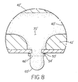
- Figures 8-10 are cross sectional views of the nozzle tip of an ink jet print head of Figure 6 in different stages of operation.
-
- The present description will be directed in particular to elements forming part of, or cooperating more directly with, apparatus in accordance with the present invention. It is to be understood that elements not specifically shown or described may take various forms well known to those skilled in the art.
- Figure 6 is a detail enlargement of a cross-sectional view of a single nozzle of the drop-on-demand ink jet print head according to a preferred embodiment of the present invention. An ink delivery channel 40', along with a plurality of cylindrical nozzle bores 46' are etched in a
silicon substrate 42', which is silicon in this example. In this example, delivery channel 40' and nozzle bore 46' were formed by anisotropic wet etching of silicon, using a p+ etch stop layer to form the shape of nozzle bore 46'. Ink 70' in delivery channel 40' is pressurized above atmospheric pressure, and forms a meniscus 60' which protrudes somewhat from nozzle rim 54' ofheater 50.' The force of surface tension, which tends to hold the drop in, balances the force of the ink pressure, which tends to push the drop out. - According to the invention, nozzle bore 46' has a very small diameter of, say about 4 microns, and preferably between about 3 and 4 microns. Even smaller nozzle bores may be operable in accordance with the present invention. Because of the small diameter, an ink meniscus in the nozzle will have a very high Laplace pressure, that is, a very high pressure due to surface tension. It can therefore counter a very high pressure in ink delivery channel 40'. Even pressures considerably above atmospheric pressure cannot overcome the Laplace pressure to eject fluid from the nozzle. In accordance with the preferred embodiment, Laplace pressures between about 1.5 atmospheres and 1.7 atmospheres are expected for a 4 microns bore.
- When a drop is desired, heater 50' along nozzle rim 54' is turned on. A typical voltage profile that would be used to drive current through the heater is shown in Figure 7. Because of the heat, the surface tension of the fluid drops, and along with it, the Laplace pressure. Figure 8 shows the emergence of meniscus60' from the nozzle just after it has been heated. Because of the very high reservoir pressure, the reduction of the Laplace pressure causes a high pressure drop that ejects a stream of fluid from the nozzle at high speed. The stream flows from the nozzle as long as the heater is left on. Figure 9 shows a schematic of the emerging stream of fluid at a time near the middle of the ejection. When enough fluid to form a drop of the desired size has flowed from nozzle bore 46', heater 50' is turned off and the increased surface tension increases the Laplace pressure and chokes off the stream. Figure 10 shows the fluid stream just after the heater has been turned off. The stream is forming into a drop at its head, and has necked off from the fluid in the reservoir at its tail. A new meniscus is formed. Some time after the termination of the heater pulse, the stream forms into a spherical drop, and the meniscus has assumed its equilibrium shape.
- We have found surprisingly that for bore diameters less than about 4 microns and for pulses longer than the time required for meniscus volume doubling, a cylindrical stream of arbitrary volume is ejected, the volume being proportional to pulse length, ink velocity, and bore area. The variation in drop volume can be three fold or larger. Referring again to Figure 6, the rear wall of the ink chamber may be moveable away from nozzle bore 46' to rapidly decrease to pressure of ink in chamber 70'. The wall is triggered at regular intervals in such a way as to send a negative pressure pulse through the ink to all of the nozzles, at time F' in Figure 11. Time F' nearly coincides with time E', that time at which the heater pulse is terminated. In this way, the negative pressure caused by the movement of the wall aids in the termination of the streams. In this embodiment, the wall is preferably a piezoelectric element.
Claims (9)
- Apparatus for controlling ink in an ink jet printer, said apparatus comprising:an ink delivery channel;a source of pressurized ink communicating with the ink delivery channel;a nozzle bore which opens into the ink delivery channel to establish an ink flow path, the nozzle bore defining a nozzle bore perimeter, inherent surface tension of pressurized ink in the nozzle bore forming an ink meniscus;a selectively-actuated heater associated with the nozzle bore to cause a reduction in the surface tension of the ink when activated such that ink flows from the nozzle bore in a continuous stream substantially for the duration of activation of the heater only.
- Apparatus as set forth in Claim 1 wherein said nozzle bore is about 4 microns in diameter.
- Apparatus as set forth in Claim 1 wherein said nozzle bore is less than 4 microns in diameter.
- Apparatus as set forth in Claim 1 wherein said nozzle bore is about 3 microns in diameter.
- Apparatus as set forth in Claim 1 wherein said nozzle bore is between 3 and 4 microns in diameter.
- Apparatus as set forth in Claim 1 further comprising a controller for activating the heater for a time period longer than the time required for the ink meniscus to double in volume.
- Apparatus as set forth in Claim 1 wherein source of pressurized ink provides ink at the nozzle bore up to about 1.7 atmospheres.
- Apparatus as set forth in Claim 1 wherein source of pressurized ink provides ink at the nozzle bore between about 1.5 and 1.7 atmospheres.
- Apparatus as set forth in Claim 1 further comprising a device adapted to rapidly decrease pressure of ink communicating with the ink delivery channel following the duration of activation of the heater only.
Applications Claiming Priority (2)
| Application Number | Priority Date | Filing Date | Title |
|---|---|---|---|
| US738922 | 2000-12-15 | ||
| US09/738,922 US6394585B1 (en) | 2000-12-15 | 2000-12-15 | Ink jet printing using drop-on-demand techniques for continuous tone printing |
Publications (3)
| Publication Number | Publication Date |
|---|---|
| EP1216834A2 true EP1216834A2 (en) | 2002-06-26 |
| EP1216834A3 EP1216834A3 (en) | 2003-06-11 |
| EP1216834B1 EP1216834B1 (en) | 2005-10-12 |
Family
ID=24970041
Family Applications (1)
| Application Number | Title | Priority Date | Filing Date |
|---|---|---|---|
| EP01204640A Expired - Lifetime EP1216834B1 (en) | 2000-12-15 | 2001-12-03 | Ink jet printing using drop-on-demand techniques for continuous tone printing |
Country Status (3)
| Country | Link |
|---|---|
| US (1) | US6394585B1 (en) |
| EP (1) | EP1216834B1 (en) |
| DE (1) | DE60113953T2 (en) |
Families Citing this family (12)
| Publication number | Priority date | Publication date | Assignee | Title |
|---|---|---|---|---|
| US7051654B2 (en) * | 2003-05-30 | 2006-05-30 | Clemson University | Ink-jet printing of viable cells |
| US7146084B2 (en) * | 2003-06-16 | 2006-12-05 | Cmc Electronics, Inc. | Fiber optic light source for display devices |
| US7364276B2 (en) * | 2005-09-16 | 2008-04-29 | Eastman Kodak Company | Continuous ink jet apparatus with integrated drop action devices and control circuitry |
| US7785496B1 (en) | 2007-01-26 | 2010-08-31 | Clemson University Research Foundation | Electrochromic inks including conducting polymer colloidal nanocomposites, devices including the electrochromic inks and methods of forming same |
| ES2685638T3 (en) | 2011-07-26 | 2018-10-10 | The Curators Of The University Of Missouri | Artificially produced edible meat |
| WO2015038988A1 (en) | 2013-09-13 | 2015-03-19 | Modern Meadow, Inc. | Edible and animal-product-free microcarriers for engineered meat |
| JP2017505138A (en) | 2014-02-05 | 2017-02-16 | モダン メドー インコーポレイテッド | Dried food formed from cultured myocytes |
| EP3337923B2 (en) | 2015-09-21 | 2023-01-04 | Modern Meadow, Inc. | Fiber reinforced tissue composites |
| JP7109882B2 (en) | 2016-02-15 | 2022-08-01 | モダン メドウ,インコーポレイテッド | Method for making biofabricated materials containing collagen fibrils |
| AU2018253595A1 (en) | 2017-11-13 | 2019-05-30 | Modern Meadow, Inc. | Biofabricated leather articles having zonal properties |
| AU2020209847B2 (en) | 2019-01-17 | 2024-10-17 | Modern Meadow, Inc. | Layered collagen materials and methods of making the same |
| EP4143258A4 (en) | 2020-05-01 | 2024-05-22 | Modern Meadow, Inc. | PROTEIN-POLYURETHANE ALLOYS AND LAYERED MATERIALS INCLUDING THE SAME |
Citations (7)
| Publication number | Priority date | Publication date | Assignee | Title |
|---|---|---|---|---|
| US1941001A (en) | 1929-01-19 | 1933-12-26 | Rca Corp | Recorder |
| US3878519A (en) | 1974-01-31 | 1975-04-15 | Ibm | Method and apparatus for synchronizing droplet formation in a liquid stream |
| GB2007162A (en) | 1977-10-03 | 1979-05-16 | Canon Kk | Liquid jet recording process and apparatus therefor |
| US4490728A (en) | 1981-08-14 | 1984-12-25 | Hewlett-Packard Company | Thermal ink jet printer |
| US4646106A (en) | 1982-01-04 | 1987-02-24 | Exxon Printing Systems, Inc. | Method of operating an ink jet |
| US5739832A (en) | 1994-11-24 | 1998-04-14 | Pelikan Produktions Ag | Droplet generator for generating micro-drops, specifically for an ink-jet printer |
| US6079821A (en) | 1997-10-17 | 2000-06-27 | Eastman Kodak Company | Continuous ink jet printer with asymmetric heating drop deflection |
Family Cites Families (3)
| Publication number | Priority date | Publication date | Assignee | Title |
|---|---|---|---|---|
| US6022099A (en) * | 1997-01-21 | 2000-02-08 | Eastman Kodak Company | Ink printing with drop separation |
| US6498615B1 (en) * | 1997-08-26 | 2002-12-24 | Eastman Kodak Company | Ink printing with variable drop volume separation |
| US6273552B1 (en) * | 1999-02-12 | 2001-08-14 | Eastman Kodak Company | Image forming system including a print head having a plurality of ink channel pistons, and method of assembling the system and print head |
-
2000
- 2000-12-15 US US09/738,922 patent/US6394585B1/en not_active Expired - Fee Related
-
2001
- 2001-12-03 DE DE60113953T patent/DE60113953T2/en not_active Expired - Fee Related
- 2001-12-03 EP EP01204640A patent/EP1216834B1/en not_active Expired - Lifetime
Patent Citations (7)
| Publication number | Priority date | Publication date | Assignee | Title |
|---|---|---|---|---|
| US1941001A (en) | 1929-01-19 | 1933-12-26 | Rca Corp | Recorder |
| US3878519A (en) | 1974-01-31 | 1975-04-15 | Ibm | Method and apparatus for synchronizing droplet formation in a liquid stream |
| GB2007162A (en) | 1977-10-03 | 1979-05-16 | Canon Kk | Liquid jet recording process and apparatus therefor |
| US4490728A (en) | 1981-08-14 | 1984-12-25 | Hewlett-Packard Company | Thermal ink jet printer |
| US4646106A (en) | 1982-01-04 | 1987-02-24 | Exxon Printing Systems, Inc. | Method of operating an ink jet |
| US5739832A (en) | 1994-11-24 | 1998-04-14 | Pelikan Produktions Ag | Droplet generator for generating micro-drops, specifically for an ink-jet printer |
| US6079821A (en) | 1997-10-17 | 2000-06-27 | Eastman Kodak Company | Continuous ink jet printer with asymmetric heating drop deflection |
Also Published As
| Publication number | Publication date |
|---|---|
| DE60113953D1 (en) | 2005-11-17 |
| US6394585B1 (en) | 2002-05-28 |
| US20020075355A1 (en) | 2002-06-20 |
| DE60113953T2 (en) | 2006-07-20 |
| EP1216834A3 (en) | 2003-06-11 |
| EP1216834B1 (en) | 2005-10-12 |
Similar Documents
| Publication | Publication Date | Title |
|---|---|---|
| EP0856403B1 (en) | Ink ejecting printhead and process | |
| EP1116586B1 (en) | Assisted drop-on-demand inkjet printer | |
| JP4787304B2 (en) | Image printing apparatus and method for separating ink droplets | |
| EP0864423B1 (en) | Ink transfer printing apparatus with drop volume adjustment and process therefor | |
| US5812159A (en) | Ink printing apparatus with improved heater | |
| EP1219431B1 (en) | A drop-masking continuous inkjet printing method and apparatus | |
| US20040095441A1 (en) | Method and apparatus for printing ink droplets that strike print media substantially perpendicularly | |
| US6273552B1 (en) | Image forming system including a print head having a plurality of ink channel pistons, and method of assembling the system and print head | |
| JP2002225280A (en) | Device and method for printing image | |
| JP2005231364A (en) | Device for using bubbles as a substantial valve in a micro-injector for jetting liquid | |
| EP1216834B1 (en) | Ink jet printing using drop-on-demand techniques for continuous tone printing | |
| JPH10128977A (en) | Print head and formation of droplets | |
| JP2002210981A (en) | Ink jet unit having amplified asymmetrically heated droplet deflection | |
| JPH11216867A (en) | Continuous ink jet printer with binary electrostatic deflection | |
| US6126270A (en) | Image forming system and method | |
| US6488362B2 (en) | Inkjet printhead with nozzle pokers | |
| JPH11188878A (en) | Continuous ink jet printer equipped with liquid drop deflection means by micromechanical actuator | |
| WO2001072429A2 (en) | Apparatus for using bubbles as virtual valve in microinjector to eject fluid | |
| US6498615B1 (en) | Ink printing with variable drop volume separation | |
| JP3165717B2 (en) | Ink jet recording head and recording method using the same | |
| JPS63139749A (en) | inkjet recording head | |
| US6830320B2 (en) | Continuous stream ink jet printer with mechanism for asymmetric heat deflection at reduced ink temperature and method of operation thereof | |
| US6250740B1 (en) | Pagewidth image forming system and method | |
| US6425654B1 (en) | Ink jet print head with tapered nozzle chambers | |
| US20140307033A1 (en) | Pre-heating liquid ejected from a liquid dispenser |
Legal Events
| Date | Code | Title | Description |
|---|---|---|---|
| PUAI | Public reference made under article 153(3) epc to a published international application that has entered the european phase |
Free format text: ORIGINAL CODE: 0009012 |
|
| AK | Designated contracting states |
Kind code of ref document: A2 Designated state(s): AT BE CH CY DE DK ES FI FR GB GR IE IT LI LU MC NL PT SE TR |
|
| AX | Request for extension of the european patent |
Free format text: AL;LT;LV;MK;RO;SI |
|
| PUAL | Search report despatched |
Free format text: ORIGINAL CODE: 0009013 |
|
| AK | Designated contracting states |
Designated state(s): AT BE CH CY DE DK ES FI FR GB GR IE IT LI LU MC NL PT SE TR |
|
| AX | Request for extension of the european patent |
Extension state: AL LT LV MK RO SI |
|
| 17P | Request for examination filed |
Effective date: 20031114 |
|
| AKX | Designation fees paid |
Designated state(s): DE FR GB |
|
| 17Q | First examination report despatched |
Effective date: 20040604 |
|
| GRAP | Despatch of communication of intention to grant a patent |
Free format text: ORIGINAL CODE: EPIDOSNIGR1 |
|
| GRAS | Grant fee paid |
Free format text: ORIGINAL CODE: EPIDOSNIGR3 |
|
| GRAA | (expected) grant |
Free format text: ORIGINAL CODE: 0009210 |
|
| AK | Designated contracting states |
Kind code of ref document: B1 Designated state(s): DE FR GB |
|
| REG | Reference to a national code |
Ref country code: GB Ref legal event code: FG4D |
|
| PGFP | Annual fee paid to national office [announced via postgrant information from national office to epo] |
Ref country code: FR Payment date: 20051020 Year of fee payment: 5 |
|
| PGFP | Annual fee paid to national office [announced via postgrant information from national office to epo] |
Ref country code: DE Payment date: 20051031 Year of fee payment: 5 |
|
| REF | Corresponds to: |
Ref document number: 60113953 Country of ref document: DE Date of ref document: 20051117 Kind code of ref document: P |
|
| ET | Fr: translation filed | ||
| PLBE | No opposition filed within time limit |
Free format text: ORIGINAL CODE: 0009261 |
|
| STAA | Information on the status of an ep patent application or granted ep patent |
Free format text: STATUS: NO OPPOSITION FILED WITHIN TIME LIMIT |
|
| 26N | No opposition filed |
Effective date: 20060713 |
|
| PG25 | Lapsed in a contracting state [announced via postgrant information from national office to epo] |
Ref country code: DE Free format text: LAPSE BECAUSE OF NON-PAYMENT OF DUE FEES Effective date: 20070703 |
|
| GBPC | Gb: european patent ceased through non-payment of renewal fee |
Effective date: 20061203 |
|
| REG | Reference to a national code |
Ref country code: FR Ref legal event code: ST Effective date: 20070831 |
|
| PG25 | Lapsed in a contracting state [announced via postgrant information from national office to epo] |
Ref country code: GB Free format text: LAPSE BECAUSE OF NON-PAYMENT OF DUE FEES Effective date: 20061203 |
|
| PG25 | Lapsed in a contracting state [announced via postgrant information from national office to epo] |
Ref country code: FR Free format text: LAPSE BECAUSE OF NON-PAYMENT OF DUE FEES Effective date: 20070102 |
|
| PGFP | Annual fee paid to national office [announced via postgrant information from national office to epo] |
Ref country code: GB Payment date: 20051104 Year of fee payment: 5 |