EP1216342B1 - Subsea lubricator device and methods of circulating fluids in a subsea lubricator - Google Patents
Subsea lubricator device and methods of circulating fluids in a subsea lubricator Download PDFInfo
- Publication number
- EP1216342B1 EP1216342B1 EP00964792A EP00964792A EP1216342B1 EP 1216342 B1 EP1216342 B1 EP 1216342B1 EP 00964792 A EP00964792 A EP 00964792A EP 00964792 A EP00964792 A EP 00964792A EP 1216342 B1 EP1216342 B1 EP 1216342B1
- Authority
- EP
- European Patent Office
- Prior art keywords
- passage
- bypass
- well
- christmas tree
- fluid
- Prior art date
- Legal status (The legal status is an assumption and is not a legal conclusion. Google has not performed a legal analysis and makes no representation as to the accuracy of the status listed.)
- Expired - Lifetime
Links
Images








Classifications
-
- E—FIXED CONSTRUCTIONS
- E21—EARTH OR ROCK DRILLING; MINING
- E21B—EARTH OR ROCK DRILLING; OBTAINING OIL, GAS, WATER, SOLUBLE OR MELTABLE MATERIALS OR A SLURRY OF MINERALS FROM WELLS
- E21B33/00—Sealing or packing boreholes or wells
- E21B33/02—Surface sealing or packing
- E21B33/03—Well heads; Setting-up thereof
- E21B33/068—Well heads; Setting-up thereof having provision for introducing objects or fluids into, or removing objects from, wells
- E21B33/072—Well heads; Setting-up thereof having provision for introducing objects or fluids into, or removing objects from, wells for cable-operated tools
Definitions
- the invention relates to a subsea lubricator device, comprising a blowout preventer assembly, a tool housing assembly and a stuffing box, intended to be located at a subsea Christmas tree.
- the invention relates to methods of circulating fluids in a subsea lubricator.
- Works are performed in an oil or gas well, among others, to stimulate or treat the well to increase production, to replace various equipment such as valves, to make measurements, to monitor the state of the well, or anything else being required.
- a pressure barrier has be established in the form of a blowout preventer. This may vary from simple stop valves to large drilling BOPs.
- circulating fluids in the well may be needed, whereby possible pressure increase in the well may be controlled.
- a subsea lubricator consists of a first, or lower assembly in the form of a blowout preventer, including valves for controlling the well pressure, cutting of wire, etc, a second component located above this and comprising of a tool housing with associated equipment, and uppermost a grease injector head (or stuffing box, depending on the kind of wire being used).
- the latter comprises devices for supply of grease under pressure into the grease injector head.
- This both lubricates the wire, whereby it slides more easily therethrough, and provides sealing between the wire and the gate, whereby possible well fluids may not be discharged into the environment.
- the tool housing has a length corresponding to appoximately the length of the tool suspended at the end of the wire, normally 15-25 meters.
- Such a lubricator may not be used for circulation in the well.
- Another disadvantage is the practical problems of being able to circulate out unwanted fluids entering the lubricator. Hydrocarbons, or other contaminating fluids entering the lubricator during the work may not be discharged into the surroundings, from environmental reasons.
- such fluids are removed from the lubricator by means of a special return line being able to convey the fluid upwardly into the vessel at the surface.
- the vessel must have equipment for treatment of the fluids, i.e. hydrocarbons, in a proper way, which means increasing costs (larger vessel, etc.).
- the present invention relates to an improvement of a subsea lubricator, and methods of circulating out fluids from such a lubricator.
- An object of the invention is to provide a lubricator being less heavy and less expensive, and a method of more easily circulating fluids therefrom for well intervention.
- a second object of the invention is to provide a subsea lubricator comprising means for circulating the well.
- a third object of the invention is to provide means, permitting unwanted fluids in the tool to be circulated back into the well instead of to the vessel.
- An additional object of the invention is to provide a subsea lubricator which may be used at large depths.
- An important aspect of the invention is to avoid formation of hydrates caused by water contacting hydrocarbones.
- a lubricator comprising at least one bypass, whereby fluids may be circulated back to the well, or into a flow line. Moreover, it is advantageous that the circulation may occur from different levels of the lubricator, and also that the bypasses may be opened/closed independently of one another.
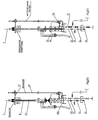
- Fig. 1 the components of a subsea lubricator arranged to be located at a conventional Christmas tree are shown diagrammatically.
- the lubricator consists of three main components, a pressure control assembly (blowout preventer) 40 which comprises valves controlling the well during the intervention operation.
- a tool housing assembly 60 comprises a tubular column for a tool which shall be run downwardly in the well.
- a stuffing box, or a grease injector head 64 is located for slidable but sealed leadthrough of the cable, or wire suspending the tool. All the three components are connected to one another by means of connector devices.
- components of the Christmas tree and the well are shown diagrammatically.
- the well is completed by a tubing 1 having a downhole safety valve 2, in accordance with standard practice.
- the tubing defines an annulus (not shown) between itself and the well casing.
- a valve (not shown) may be installed in the tubing, permitting fluid communication between the interior of the tubing and the annulus downwards in the well.
- the Christmas tree 10 is of a usual type well known by the skilled person and, therefore, only its main features will be described.
- the production passage 12 of the Christmas tree has a production master valve 14 and a production swab valve 15.
- An outlet 13, having a production wing valve 16, is located between these.
- the outlet 13 communicates with a conduit 17 ending in a connector 6 for a flow line 5 extending to a manifold, or to a production vessel.
- the annulus passage 22 of the Christmas tree has the same type of valves, namely an annulus master valve 24, an annulus swab valve 25, and an annulus wing valve 26.
- the annulus wing valve is located in a lateral outlet 23 and used for control of a possible overpressure in the well annulus.
- the outlet 23 may communicate with the pipe 17 through a crossover (not shown).
- the Christmas tree is connected to the wellhead using a standard wellhead connector 11.
- a standard wellhead connector 11 This may for instance be of a type comprising a dual completion, where the passage 12 communicates with the tubing 1, and the annulus passage 22 communicates with the well annulus. It is connected sealingly to a tubing hanger in the wellhead. This enables fluid to be circulated downwardly in the well through the tubing and upwardly through the annulus, or vice versa.
- Profiles 19, respectively 29, are machined in the tubing hanger, into which plugs may be inserted to close the well.
- the top of the Christmas tree 10 is closed by a removable cap (not shown).
- This functions as a secondary barrier (in addition to the valve 15), this being required as a supplementary protection against discharge of oil or gas into the environment.
- the cap will also prevent water from penetrating into the Christmas tree. This is removed when work is to be performed in the well.
- the cap is provided with conduits extending therethrough for the supply of hydraulic fluid to the valves in the Christmas tree. Therefore, when the cap is removed, the hydraulic connection is broken. This is done intentionally, as in this manner it is ensured that all of the valves in the Christmas tree are, or will be closed, nor can be opened from the control room at the production platform after the cap has been removed. This is very important as the valves have to be closed when the cap is removed, before attachment of the pressure control device 40 to the Christmas tree.
- Fig. 23 is a sketch corresponding to Fig. 1, showing the lubricator installed on a horizontal Christmas tree (HXT), indicated generally by the numeral 100, having a ball valve and a plug as the two barriers.
- HXT horizontal Christmas tree
- the Christmas tree is of known construction and will hereinafter be described only to show the differences between this and the conventional Christmas tree.
- components having functions corresponding to components in the conventional Christmas tree have been given corresponding reference numerals, with the addition of 100. Similar components have the same reference numerals.
- the horizontal Christmas tree has a production passage 112 and an outlet 113.
- a master valve 114 and a wing valve 116 are located in the outlet 113.
- a double barrier shall always be established in the Christmas tree, in order to safeguard against discharges from the well.
- this is provided by the valve 15 and the cap, as described above.
- the barriers consist of the ball valve 115 and the plug 118.
- the ball valve is located in an internal tree cap having the same function as the tree cap, discussed previously in connection with the conventional Christmas tree, but arranged, as its name implies, within the upper part of the Christmas tree.
- the plug is located in a machined profile in the tubing hanger passage.
- a master valve 124 and a workover valve 131 are located in a lateral passage 122 of the Christmas tree.
- a bypass 123 connects the lateral passage with the outlet 117 from the production passage, controlling possible overpressure in the well annulus.
- a stop valve 132 is located in this "crossover”
- Fig. 24 is a diagrammatical sketch corresponding to Fig. 23, wherein the Christmas tree is a horizontal Christmas tree (HXT), indicated generally by the reference numeral 200, having crown plug. This means that the ball valve has been replaced by a plug located in the internal tree cap. Otherwise, this Christmas tree is identical to the one discussed above.
- HXT horizontal Christmas tree
- FIG. 1 components corresponding to components of the conventional Christmas tree have been given the same reference numerals as in Fig. 1 but with the addition of 200. Similar components have the same reference numerals.
- the crown plug 215, replacing the ball valve, is located in the internal tree cap, while the second plug 218 is located in the tubing hanger.
- the master valve 14 (114, 214) and the wing valve 16 (116, 216) are kept open, whereby the well fluids are directed into the outlet 13 and the flow line 5. Normally, all the other valves in the Christmas tree are closed.
- the pressure control or blowout preventer assembly includes in general a number of valves which ensure control of the well during intervention. Particularly, this component has been developed for use in the present invention and, thus, will hereinafter be referred to as a LIP-assembly ("Lower Intervention Package").
- the LIP-assembly includes a number of valves, controlling the well during intervention. These may for instance be (seen from the bottom upwardly) a pipe ram 43, i.e. a valve being able to grip around a cable, or a wire, preventing the tool from falling downwardly in the well, if the wire suspending the tool has to be cut. Further there are a shear ram 44 and a blind ram (gate valve) 45. It shall be noted that additional such valves may be present and arranged in another orders than the one discussed above.
- the lower part of the LIP-assembly comprises connector means 41 for attachment at the upper part of the Christmas tree.
- the connector means 41 is part of an adapter 90 comprising, among others, the connector means 41 mentioned above in addition to connector devices, securing the adapter to the LIP-assembly.
- the lubricator may be easily adapted for use with connector profiles in various types of Christmas trees.
- the adapter may have other functions which will be described later.
- the adapter comprises passages 91, 92, as shown in Fig. 6, communicating with the production passage 12 and the annulus passage 22 in the Christmas tree, respectively.
- the passage 91 communicates with a passage 42 in the LIP-assembly.
- the passages 42, 91 and 12 have coincident axes, i.e. they extend in-line with one another.
- the adapter comprises passages (not shown) for supply of hydraulic fluid into the valves in the Christmas tree, whereby these may be opened and closed during the intervention process. These are communicating with hydraulic lines (not shown) in an umbilical 30 and are controlled by a control module 49.
- the valves in the Christmas tree may be opened and closed in this manner during the intervention process.
- bypass 46 is located in the LIP-assembly.
- the bypass is formed as a separate pipe connected removably to the side of the LIP-assembly, as shown in Fig. 1.
- the bypass 46 provides a fluid passage around the valves in the LIP-assembly. In the embodiment shown in Figs. 3 - 6 the lowermost of the bypass is inserted into the adapter 90.
- bypass 46 may be formed as a passage in the LIP-assembly.
- a first valve assembly is located in connection with the LIP-assembly.
- the valve assembly consists of a number of valves, conduit pieces etc., forming an assembly fastened to the adapter 90.
- valve assembly may for instance be a part of the adapter.
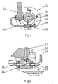
- valve assembly The components of the valve assembly are shown more detailed in Figs. 4 and 5. It comprises two inlets communicating with the bypass 46 and a fluid supply line 47, respectively.
- Check valves 55 and 56 may be located in the inlets, enabling fluid to flow only into the valve body.
- two outlets namely a first outlet 53 communicating with the main passage 91 in the adapter (and, thereby, the production passage 12 of the well), and a second outlet which via a passage 52 provide fluid communication into the second passage 92 in the adapter communicating with the annulus passage 22 of the Christmas tree.
- a stop valve 57 is located in the inlet 47.
- a stop valve 57 is located in the outlet 53.
- the upper part 60 of the lubricator comprises a tool housing 63 for receipt of a tool which shall be inserted in the well. This is secured removably to the LIP -assembly by connecting means 61, whereby the passage 62 in the tool housing is in axial extension of the passage 42 (Fig. 6).
- shear and support rams 68, 69 may be placed at the upper part of the tool housing.
- the lubricator may comprise meters and other equipment monitoring the work.
- Fig. 1 two pressure meters 67a, 67b are indicated diagrammatically.
- the tool housing assembly 63 also comprises a bypass 66, correspondingly as the LIP-assembly.
- the bypass 66 communicates with the bypass 46.
- the bypass 66 may be a pipe being removably secured to the side of the tool housing. If so, the bypass 66 has to comprise connector means 61 a, as shown diagrammatically in Fig. 1.
- the bypass may be formed as a part of a multi-passage tool housing.
- bypasses 46, 66 are separate components, these are advantageously flexible hoses.
- a fluid connection 72 is arranged between the tool housing 63 and the bypass 66.
- this is shown diagrammatically as a crossover 72.
- the fluid flow from the tool housing into the bypass pipe may be closed by means of a valve 73 arranged in the crossover 72.
- a second inlet is shown as a pipe stub 82 having connector means for attachment to an external fluid supply. The purpose of this will be explained more detailed later.
- a stop valve 74 is located in the passage 82.
- a stuffing box 64 and a pipe stub 65 are arranged which may comprise a connector profile and, possibly, an insertion tunnel facilitating insertion of the tool to be lowered downwardly in the well.
- the stuffing box is secured removably to the tool housing 63. This provides the possibility to choose whether the stuffing box shall be situated at the tool housing all the time, and adapted to be opened, whereby the tool may be led therethrough, or lowered downwardly (and withdrawn upwardly) with the tool.
- the tool housing will be made up of a number of pipes screwed together for a length of about 15 meters, enabling receipt of standard types of tools being used during intervention.
- the tool housing has connector devices at its ends.
- a lower sub 75 provides transition between the tool housing and the LIP-assembly.
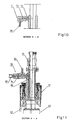
- the sub 75 comprises upper connector means 77 for attachment to the tool housing, and lower connector means for attachment to the upper connector 61 of the LIP-assembly. This is shown in Fig. 11, indicating the LIP-assembly by broken lines.
- the sub may include a tool trap 76, shown as a flap valve, which may be closed in order to prevent the tool from falling down in the well.
- the sub comprises a passage 86 providing fluid communication between the passage in the bypass 66 and a passage in the LIP-assembly (Fig. 6) communicating with the bypass 46.
- the lower sub 75 may include a lower crossover piece 78 comprising an inlet for the bypass 66, and an additional inlet 89 for an external fluid supply.
- a stop valve is located in the inlet 89.
- a upper sub 79 is connected removably to the top of the tool housing, and comprises the control valves 68, 69 mentioned above, and a housing for insertion of the stuffing box 64. Uppermost the sub ends in a pipe stub 65, possibly having an insertion hopper facilitating insertion of the tool into the tool housing.
- An upper crossover piece 71 (Fig. 10) is secured to the sub 79.
- the crossover piece 71 has a passage 72, communicating with the passage 62 of the tool housing and the passage 66 of the bypass.
- the bypass 66 is secured at the crossover piece 79.
- a valve 73 is located in the passage 72.
- An umbilical 30 extends from the surface to the lubricator. This comprises lines for supply of hydraulic fluid and electricity, controlling the valves in the Christmas tree (as per standard practice).
- lines for supply of chemical fluids in the drawings shown, by way of an example, as a supply line 31 for a diluent such as diesel, a line 32 for water, and two lines for a hydrate inhibiting fluid.
- the connection between the umbilical and the lubricator is shown at 36.
- Stop valves 31a-33a are located for the respective passages 31-33, controlling the supply of the various fluids.
- the line 34 is connected to the passage 47 having the stop valve 54. In this manner the fluids mentioned above may be supplied to the apparatus, and particularly into the tool housing 51.
- check valves may also be located in the passages 31-34, increasing the safeguard against discharges if the umbilical should be disconnected by an accident.
- a control module 49 may be located at the LIP-assembly, controlling the various functions during the use of the lubricator.
- Fig. 2 showing a second embodiment of the invention.
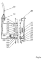
- Fig. 2a shows the lower part of the lubricator (the pressure control assembly) and
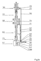
- Fig. 2b shows the upper part with the tool housing.
- a pressure control assembly 140 comprises a lower connector 141 for attachment to a Christmas tree, and an upper connector 161 for attachment to a corresponding connector at the tool housing assembly (Fig. 2a).
- the assembly consists of the following valves, mentioned from below: a lower blind ram (gate valve) 142, a pipe ram 143, a shear ram 144, and a upper stop valve 145.
- a passage 42 extends axially in the pressure control device in the same manner as discussed above.
- a first bypass 146 is arranged in a manner providing a fluid passage around the valves mentioned above.
- the bypass is shown as a pipe being connected to the connector 161 at its upper end, and communicating with the passage 42 of the LIP-assembly via a passage at its lower end.
- a stop valve is located in the bypass.
- a second bypass 147 is arranged in a manner providing a fluid passage into the lower end of the LIP-assembly. As shown the bypass 147 ends in two branches 148, 149 communicating with the passage 42 of the LIP-assembly and the annulus passage 22 of the Christmas tree, respectively (Fig. 1). Stop valves 153, 154 are located in the branch passages 148, respectively 149. At its upper end the bypass 147 has a connector stub for connecting to an external fluid supply, and for explanation of the function of this bypass reference shall be made to Fig. 17 and 18 and the corresponding description.
- An umbilical 130 extends between the surface and the lubricator.
- This comprises lines 133 for supply of hydraulic fluid and electricity for control of the valves in the Christmas tree and the lubricator (as per standard practice).
- lines 133, 134, 135 are arranged for supply of chemical fluids into the lubricator.
- the chemical fluids may be a diluent, or a hydrate inhibiting fluid, and possibly water.
- the line 134 communicates with the passage 42 at a position above the upper valve 145, the line 135 communicates with the passage 45 above the lower valve 142 and the line 136 communicates with the passage 45 below the lower valve 142.
- Stop valves 155, 156 and 157 are located in the respective lines, controlling the supply of the various fluids. In this manner fluids may be supplied to the apparatus at different positions, whereby the desired circulation is achieved.
- check valves may preferably be located in all of the passages discussed above, for increased safeguard against discharges if the connectors or valves should fail.
- a container 157 for pressurized gas preferably nitrogen gas, communicates with the main passage 42 in the LIP-assembly 160 via a supply 158 having a valve 159. This may be used to displace hydrocarbons in the lower part of the LIP-assembly.
- the tool housing assembly (Fig. 2b) includes a lower connector device 141' for attachment to the connector 141 of the LIP-assembly, further it may include (mentioned from the bottom and upwardly) a lower sub 175, the tool housing 163, a valve sub 168 comprising safety valves (cf. 68 and 69 in Fig. 1), an upper sub 179, and a sluice sub 180.
- bypasses 166, 167 are arranged along the side of the lubricator assembly, providing additional fluid passages outside the tool housing.
- the bypasses may be a integrated part of the tool housing but they are preferably pipes being bolted or attached to the outside of the tool housing in another manner, as shown in Fig. 2a.
- the bypass 166 extends between the sluice sub 180 and the connector 141', and communicates with a first passage 164 in the latter.
- the bypass 167 extends between the valve sub 168 and a second passage 163 in the connector 141'.
- the connector piece 141' comprises a main passage 242 communicating axially with the passage 42 in the LIP-assembly, when the connector 141, 141' is assembled.
- a lateral passage 243 communicates with a passage in the connector piece 141, that in turn communicates with the lower bypass 146 (Fig. 2A). Further, the passage 243 communicates with the passages 163, 164. In addition, the passage 243 also communicates with an inlet 198, whereby a hose or a pipe for external fluid supply may be connected to the passage 243.
- a stop valve 194, and possibly a pump 193, is located in the inlet 189. Check valves may also be located in the passages.
- the bypass 167 communicates with the tool housing 163 on the lower side of the valve piece 163. This permits fluid circulation when the valves 68, 69 have been closed.
- the bypass comprises a stop valve 171.
- the bypass 166 communicates with the tool housing 163 at the sluice sub 180.
- a stop valve 173 is located in the bypass.
- An additional inlet having a valve 174 is located in the valve piece 168 between the valves 68 and 69.
- the purpose of this inlet is to permit supply of a lubricant into the spacing between the valves for supplementary sealing between the cable/wire and the tool housing.
- This valve 174 is intended just for use in case of an emergency when the valves 68, 69 have to be closed.
- the sluice sub 180 comprises a widened part for receipt of a stuffing box, or a grease injector head. Locking pieces are shown, whereby the stuffing box may be properly locked during operation.
- valves 14 (114; 214) and 16 (116; 216) in the Christmas tree must be closed in order to shut in the well.
- the cap is removed and the LIP-assembly 40, having the umbilical 30 connected, is lowered from a vessel and connected to the Christmas tree, and the connection is pressure tested.
- the tool housing assembly 60 is lowered downwardly and connected to the LIP-assembly 60.
- the bypass 66 also is connected to the bypass 46.
- the connection is pressure tested.
- the lubricator is at this state filled with sea water. This situation is shown in Fig. 7.
- the stuffing box is attached rigidly to the tool housing assembly (the sub 79) in this embodiment.
- a tool 8 performing downhole works in the well, has been made ready on the vessel and is secured at the end of a wire 7.
- the tool is lowered downwardly into the lubricator.
- the stuffing box is opened.
- a ROV may be present, monitoring and assisting the insertion of the tool into the tool housing assembly.
- the stuffing box is preferably suspended by the wire 7 before lowering, and lowered with the tool 8, as indicated in Fig. 2B.
- the tool is inserted in the tool housing 163, and the stuffing box is locked within the sluice sub 180. Then, problems of sealing due to repeated opening and closing of the stuffing box are avoided.
- valves 14, 15 and 45 may not be opened for lowering the tool into the well, as this will result in penetration of hydrocarbons into the lubricator and formation of hydrates, due to the fact that the lubricator contains water at this stage. Thus, the percentage of water in the system has to be reduced before the valves may be opened. This is obtained by supplying hydrate inhibiting fluid which will be mixed with water, and which do not form hydrates together with water. Examples of such hydrate inhibiting fluids are methanol, glycol, or a special fluid called MEG (Methyl Ethyl Glycol).
- methanol any hydrate inhibiting fluid.
- Supply of methanol is performed until the water content is reduced, whereby risk of formation of hydrates no longer exists.
- valves 14 and 15 in the Christmas tree may be opened (Fig. 8).
- the valve 33a is opened for supply of methanol into the tool housing 63.
- the water will be displaced therefrom and into the bypass 66, 46 and downwardly in the well via the passage 53, alternatively into the flow line 5 (the valves 14 and 16 have been closed and opened, respectively).
- the valve 54 is also opened for supply of methanol into the flow in the bypass 46, whereby the water content of the fluids, being supplied into the well, is below the critical limit for formation of hydrates.
- valve 145 is opened and methanol is supplied through the line 135 into the LIP-assembly via the valve 142.
- the water is displaced into the bypass 166, 146 and downwardly in the well passage 12, alternatively into the pipe line 5.
- methanol is supplied through the line 136.
- valve 94 (194) may be opened instead of the valve 57 (152), whereby sea water is flushed into the environment through the outlet 89 (189).
- a possibility for attachment of an external hose exists here, whereby the fluid flushed may be brought to the vessel at the surface for processing.
- valve 45 is opened after the pressure has been balanced at both of its sides. Normally, the valves 43 and 44 are open, and will be closed only in a situation of uncontrolled blowout with the tool downwardly in the well, involving that these may cut the wire and stop the well pressure.
- hydrates may be formed in the adaper, and in the passage 12 above the valve 15.
- the system may be adjusted, preventing such formation of hydrates. This is accomplished as follows.
- the valves 45 and 83 are opened. Methanol is supplied through the lines 34, 47 and 53. The water is displaced by methanol from this region. Overpressure may be bled through the pipe 82 (by opening the valve 74). Discharges of polluting methanol from the pipe 82 may be prevented by accurate control of the fluid amount, and the time.
- the tool may be run in the well in order to perform work therein.
- the tool After the tool has performed its task down in the well, it is withdrawn up into the tool housing. Now, the stuffing box may be opened, whereby the tool may be retrieved to the surface. Now, any other possible tool may be made ready in the same manner as discussed previously in order to perform other tasks in the well.
- the tool housing contains hydrocarbons.
- the bypass 46, 66 contains a mixture of methanol and water. This situation is shown in Fig. 14. Therefore, before the stuffing box is opened (or retrieved), replacement of the gas and the oil in the tool housing by water (not polluting) is necessary. Previously, this was accomplished by circulating the hydrocarbons via the umbilical to the surface, involving the need for expensive collecting and/or processing equipment at the vessel. This may be done by means of the outlets 89 (189) but the purpose of the invention is that the hydrocarbons shall be circulated back into the well.
- the tool housing has a diameter of about 7 inches (17,5 cm), while the passage diameter of the bypass 66 is about 1 1 ⁇ 2 inches (3,7 cm).
- the flow velocity of the water is increased when it enters the bypass passage, whereby the flow velocity becomes large enough to force the gas downwardly in the well.
- a flow velocity of 2 m/s in the umbilical will be sufficient to achieve the required flushing velocity in the bypass.
- an important aspect of the invention is providing an effective circulation in the lubricator (large flow velocity in the bypass) with low flow velocity in the umbilical.
- Low pressure losses are obtained by pumping the liquids having low velocity through the umbilical, something being particularly important over long distances.
- High flow velocity in the umbilical will cause large friction losses, particularly in long umbilicals.
- valve 159 in the embodiment according to Fig. 2, may be opened in such instances. Then, nitrogen under pressure will flow from the container 157, and force well fluid into the well, respectively into the flow line 5 .
- the stuffing box may be opened and the tool withdrawn to the surface. If desired, the tool may be replaced by another tool and the whole operation performed once more. If the operation has resulted in increase of pressure in the lubricator, the pressure may be safely bled by opening the valve 74.
- all of the lubricator may be withdrawn to the surface.
- the connector 61 is loosened, and the tool housing is withdrawn.
- the connector 41 is loosened, and the LIP-assembly is withdrawn, along with the adapter.
- the tool is modified, to enable circulating of the well. Such operations are used to supply fluids for chemical treatment into the well (and circulating these out after the treatment has been accomplished).
- the tool housing (and the upper bypass) are disconnected at 61.
- This situation is shown in Fig. 17.
- Two supply lines are connected to the LIP-assembly at the connectors 61 and 61 a. These may be rigid pipes, hoses, or a combination thereof, and having reference numerals 84 and 85.
- the supply lines end in a termination head having two passages adapted for the connector 61 in a first embodiment (cf. Fig. 3).
- the lower sub 75 is maintained.
- the line 85 is connected at 77 and the pipe 84 is connected to the inlet 89 of the crossover 78.
- the valve 45 is opened, while the valve 57 is kept closed. Thereby, fluid may be circulated downwardly through the bypass 46, further through the branch pipe 52 into the lateral passage 22 in the Christmas tree 10, downwardly in the well annulus. The fluid may flow into the tubing 1 via the valve in the tubing and upwardly through the passage 12 in the Christmas tree, and therefrom through the passage 42 in the LIP-assembly and into the vessel through the line 85.
- the supply pipe 84 is connected to the bypass 147.
- the bypass 147 has larger diameter than the bypass 146, whereby a larger flow is obtained therethrough during the circulation.
- the direction of circulating may be reversed, i.e. down the passages 42, 12 and up the passages 22, 52, 42.
- the tool housing may be situated at the assembly and the line 85 be connected above the stuffing box, while the second line 84 is connected to the cross piece 82.
- the valve 73 is closed during this operation.
- valves in the Christmas tree can be closed and the valve 53 opened. Now, remaining fluid situated in the lubricator may be circulated out before the lines 84, 85 are disconnected.
- the invention enables killing of the well by so-called "bullheading", i.e. forcing fluid downwardly in the well against the well pressure.
- bullheading i.e. forcing fluid downwardly in the well against the well pressure.
- the bypass provides access into the well.
- special killing fluids may be pumped into the well through the bypass, whereby the well is "killed” and control is restored.
- this operation may be performed by means of the additional bypass, shown in Fig. 2, causing better flow therethrough due to its larger diameter.
- the apparatus may be used to shut down the well by insertion of plugs into the plug profiles in the tubing hanger either in the main passage 19, or in the lateral passage (the annulus passage) 29.
- an adapter of the kind discussed above (Fig. 3) is used, the passages 42, 62 of the lubricator being in line with the main passage 12 of the Christmas tree.
- a running tool is used to run, and to locate, or in turn to retrieve the plug. Circulating out fluids is done in the same manner as discussed previously.
- FIG. 6 Another adapter 190 is connected to the LIP-assembly, as shown in Fig. 6. This is designed such that, during attachment of the lubricator to the Christmas tree, the passage 42 of the LIP-assembly extends axially in the extension of the passage in the adapter, which in turn is in connection with the annulus passage 22 in the Christmas tree.
- the production passage 12 of the Christmas tree will have fluid communication with the bypass 46 via the passage 192 in the adapter. Thereby, circulation may also be maintained during such operations.
- a running tool is run downwardly and inserted into the tool housing in the same manner as discussed previously. Fluids (i.e. water) are circulated into the well, correspondingly as when the tool is completed for ordinary use, as discussed previouly. This situation is shown in Fig. 15.
- valves 24, 25 are opened and the tool run downwardly with the annulus plug for insertion of this.
- both the tool housing and the bypass pipe contain a mixture of methanol and water (usually 50/50).
- the valves 14, 15 in the Christmas tree are closed, while the valves 24, 25 in the lateral passage are open.
- the downhole safety valve 2 is also closed. This situation is shown in Fig. 16
- the tool 8 is withdrawn upwardly in the tool housing and the valves 24, 25 in the Christmas tree are closed. After this stage, the tool housing will also contain oil and gas which must be removed before the running tool is disconnected. This is accomplished in the same manner as discussed previously. This situation is shown in Fig. 17.
- valves When the tool housing has been filled with water, all the valves can be closed and the stuffing box may be withdrawn to the surface together with the tool, or the stuffing box can be opened and the tool withdrawn therethrough. Overpressure in the lubricator may be bled by opening the valve 83, as discussed above.
- the apparatus being used for well intervention is shown used with a vertical (conventional) Christmas tree.
- the apparatus may be used with horizontal Christmas trees, referring to Figs. 18 and 19.
- the Christmas tree comprises a ball valve. This must be opened to achieve access into the Christmas tree.
- another adapter 290 is used, as shown in Fig. 20.
- This adapter comprises a valve actuator (not shown), for opening the ball valve 115 when the LIP-assembly has been connected to the Christmas tree.
- the adapter comprises a passage 294 providing the axial extension of the passage 12 up to the passage 42.
- a second passage 292 provides fluid communication between the bypass 46 and the annulus 293 in the Christmas tree.
- a pulling tool 8 for plugs is connected to the wire 7 and the stuffing box 64 is opened, whereby the tool may be inserted into the tool housing 63, as discussed previously.
- the tool housing contains water having to be removed, or thinned before use.
- direct access into the well is not available until the plug 118 has been removed.
- pumping of fluids downwardly in the well (or in the tubing) is impossible.
- the workover valve 131 is opened. Now, there are several alternatives. The preferred embodiment is to open the valve 132. Fluid is pumped down into the well, or into the flow line 5, if the valve 116 is opened. This situation is shown in Fig. 21.
- annulus master valve 124 If the annulus master valve 124 is opened, fluid may be pumped down into the well annulus. However, this may be difficult (undesirable pressure increase) and is not preferred.
- the valve 45 can be opened and the tool can withdraw the plug 118.
- the valves 131 and 132 are closed. Hydrocarbons in the tool housing is circulated into the well, as discussed previously in connection with a conventional Christmas tree. This is shown in Fig. 22.
- the method described above must be performed twice. First, water has to be removed by circulating the water through the workover valve, as discussed. After withdrawal of the first plug, access into the well is not available.
- the lubricator may also contain hydrocarbons. Removal of the hydrocarbons is accomplished in the same manner as discussed in connection with the conventional Christmas tree, apart from the hydrocarbons being circulated through the crossover, into the well or into the flow line.
- the master valve 14 may be closed and the wing valve 16 be opened, whereby the displaced fluid is forced into the flow line.
- This may be desirable, for instance if the pressure in the well is at a level making it difficult to force the fluids into the well.
- an underpressure facilitating the circulating of fluids in the pipe line may for instance be provided.
- valve 142 may be closed and methanol be supplied through the line 135, whereby the hydrocarbons will be flushed into the well. Then, the stuffing box may be opened, as escape of some methanol into the environment is no problem.
Landscapes
- Geology (AREA)
- Life Sciences & Earth Sciences (AREA)
- Engineering & Computer Science (AREA)
- Mining & Mineral Resources (AREA)
- Environmental & Geological Engineering (AREA)
- Fluid Mechanics (AREA)
- Physics & Mathematics (AREA)
- General Life Sciences & Earth Sciences (AREA)
- Geochemistry & Mineralogy (AREA)
- Earth Drilling (AREA)
- Pipeline Systems (AREA)
- Lubricants (AREA)
- Physical Or Chemical Processes And Apparatus (AREA)
Description
- Fig. 1
- is a diagrammatic sketch showing the components of the system,
- Fig. 2a-2b
- are drawings corresponding to Fig. 1, of a second embodiment of the system components, and Fig. 2b being in extension of Fig. 2a,
- Fig. 3
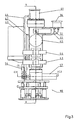
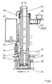
- is an elevational view showing the pressure control assembly,
- Fig. 4
- is a horizontal section along the line C2-C2 in Fig. 3,
- Fig. 5
- is a vertical section showing a detail along the line C1-C1 in Fig. 3,
- Fig. 6
- is a vertical section of the pressure control assembly along the line A-A in Fig. 3,
- Fig. 7
- is a vertical section corresponding to Fig. 6, of a second embodiment of the pressure control assembly,
- Fig. 8
- is a vertical section corresponding to Fig. 6, of a third embodiment of the pressure control assembly,
- Fig. 9
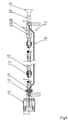
- is an elevational view showing the tool housing assembly,
- Fig. 10
- is a vertical section along the line B-B in Fig. 9,
- Fig. 11
- is a vertical section along the line A-A in Fig. 9,
- Fig. 12-16
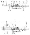
- are diagrammatic sketches showing a first method of circulating,
- Fig. 17-18
- are diagrammatic sketches showing a second method of circulating,
- Fig. 19-22
- are diagrammatic sketches showing a third method of circulating,
- Fig. 23
- is diagrammatic sketch similar to Fig. 1, showing the invention used with a horizontal Christmas tree having a ball valve and a plug,
- Fig. 24
- is a diagrammatic sketch similar to Fig. 1,showing the invention used with a horizontal type Christmas tree having two plugs, and
- Fig. 25-26
- are diagrammatic sketches of the method of circulating out, for a horizontal Christmas tree as shown in Fig. 24.
The connection between the umbilical and the lubricator is shown at 36.
In this manner fluids may be supplied to the apparatus at different positions, whereby the desired circulation is achieved.
Now, as in embodiments described previously, the tool housing contains water having to be removed, or thinned before use. However, in such Christmas trees direct access into the well is not available until the
Claims (26)
- Subsea lubricator device, comprising a blowout preventer assembly (40; 140), a tool housing assembly (60; 160) and a sealing assembly (64; 180) for a cable or wire leadthrough, intended to be located at a subsea Christmas tree (10; 100; 200) and having a passage (42, 62) therethrough which communicates with a passage (12, 22) in the Christmas tree,
characterized in that the device comprises at least one bypass (46, 66; 146, 166, 167) providing an additional fluid connection to the passages (12, 22) of the Christmas tree. - Device according to claim 1,
characterized in that the bypass is comprised of lower (46; 146, 147) and upper bypass pipes (66; 166, 167) removably connected to each other. - Device according to claim 1 or 2,
characterized in that at least the upper bypass is comprised of two bypass pipes (166, 167). - Device according to claim 1 - 3,
characterized in that the bypass comprises a fluid connection (72; 172, 195) between each of the upper bypass pipes (66; 166, 167) and the passage (62) of the tool housing (63; 163) at the upper end of the tool housing. - Device according to claim 4,
characterized in that the bypass comprises a valve assembly (51) providing fluid connection between the lower bypass pipe (46) and a passage (42) of the blowout preventer (40) at a position below the valves (43, 44) of the blowout preventer. - Device according to claim 4,
characterized in that the bypass comprises a valve assembly (152) providing fluid connection between the lower bypass pipe (146) and the passage (42) in the blowout preventer (40) at a position below the valves (142, 145) of the blowout preventer. - Device according to claim 4,
characterized in that the fluid connection (72) comprises a crossover (74), which comprises connector means (82) for attachment of an external fluid supply source (84, 87). - Device according to claim 5,
characterized in that the valve assembly (51) comprises a first inlet connected to the first bypass pipe (46), a second inlet (47) connected to an umbilical (30), a first outlet (52) connected to the production passage (12) of the Christmas tree, and a second outlet (53) connected to the annulus passage (22) of the Christmas tree. - Device according to claim 8,
characterized in that check valves (55, 56) are arranged in the inlets. - Device according to claim 8,
characterized in that a stop valve (53) is arranged in the first outlet (52). - Device according to claim 8,
characterized in that a stop valve (57) is arranged in the second outlet (53). - Device according to claim 7,
characterized in that the valve assembly (51) is a part of an adapter (90; 190; 290) - Device according to claim 12,
characterized in that the adapter (90; 190; 290) is removably attached to the blowout preventer (40), and comprises a connector device (41) which may be adapted to connector profiles for various Christmas trees (10). - Device according to claim 11 or 12,
characterized in that the adapter (90; 290) comprises a first passage (91; 294) providing an axial connection between the passage (42) in the blowout preventer (40) and the passage (12) in the Christmas tree (10), and a second passage (92) providing fluid connection between the bypass pipe (46) and the annulus passage (22) in the Christmas tree (10). - Device according to claim 11 or 12,
characterized in that the adapter (190) comprises a first passage (191) providing an axial fluid connection between the passage (42) in the blowout preventer (40) and the annulus passage (22) in the Christmas tree (10), and a second passage (192) providing fluid connection between the bypass (46) and the production passage (192) in the Christmas tree (10). - Device according to claim 12,
characterized in that the adapter (290) comprises a valve actuator. - Method of circulating fluids out of a subsea lubricator (40, 60), said lubricator comprising a blowout preventer assembly (40), a tool housing assembly (60), and a stuffing box (64), intended to be located at a subsea Christmas tree (10) and having a passage (42, 62) therethrough which communicates with a passage (12; 22) in the Christmas tree,
characterized in that a fluid is supplied into the lubricator, whereby fluids in the tool housing are displaced into at least one bypass and therefrom into the well, or into a flow line. - Method according to claim 17,
characterized in that the supplied fluid is water. - Method according to claim 17,
characterized in that the supplied fluid is a hydrate inhibiting fluid. - Method according to claim 19,
characterized in that the hydrate inhibiting fluid is methanol or glycol. - Method according to claim 17,
characterized in that the supplied fluid is a diluent. - Method according to claim 17, for removal of water from the tool housing,
characterized in that fluids are injected in the following steps:a hydrate inhibiting fluid is supplied to the tool housing (63), displacing water therefrom during simultaneous injection of a hydrate inhibiting fluid into the well. - Method according to claim 17, for removal of hydrocarbons from the tool housing,
characterized in that the fluids are injected in the following steps:at a first stage water, along with a hydrate inhibiting fluid are supplied to the tool housing, displacing hydrocarbons from the tool housing into said at least one bypass,at a second stage water is supplied to the tool housing, whereby this is filled with water, andsimultaneously supply of the hydrate inhibiting fluid in the well, whereby formation of hydrates is prevented when the water is forced into the well. - Method according to claim 17, wherein the safety valves (43, 44) of the lubricator are closed while a tool (8) being located in the well,
characterized in that a pipe (84) for external fluid supply (87) is connected to the upper bypass (at 82), whereby fluid under high pressure may be pumped downwardly in the well through the lower bypass (46), whereby the well may be killed. - Method of circulating fluids in a well using a lubricator according to claim 1,
characterized in the following steps:the tool housing (63; 163) and the upper bypass (66; 166, 167) are disconnected,a first supply pipe (85) is connected to the blowout preventer (at 61),a second supply pipe (84) is connected to a lower bypass (at 61a; 147), andfluid is circulated in the well through the bypass (46; 147), through an annulus passage (22) of the Christmas tree, and down an annulus of the well, and further into the tubing (1), up the production passage (12) of the Christmas tree and the passage (42) of the lubricator, back to the surface. - Method of circulating fluids in a well using a lubricator according to claim 1,
characterized in the following steps:the tool housing (63; 163) and the upper bypass (66; 166, 167) are disconnected,a first supply pipe (85) is connected to the blowout preventer (at 61),a second supply pipe (84) is connected to a lower bypass (at 61a; 147), andfluid is circulated in the well through the passage (42) of the lubricator and the production passage (12) of the Christmas tree, and further into the tubing (1), up the annulus of the well, the annulus passage (22) of the Christmas tree, through the bypass (46; 147), back to the surface.
Applications Claiming Priority (3)
| Application Number | Priority Date | Filing Date | Title |
|---|---|---|---|
| NO994784 | 1999-10-01 | ||
| NO994784A NO309439B1 (en) | 1999-10-01 | 1999-10-01 | Apparatus for underwater lubricator, as well as methods for circulating fluids from the same |
| PCT/NO2000/000318 WO2001025593A1 (en) | 1999-10-01 | 2000-09-28 | Subsea lubricator device and methods of circulating fluids in a subsea lubricator |
Publications (2)
| Publication Number | Publication Date |
|---|---|
| EP1216342A1 EP1216342A1 (en) | 2002-06-26 |
| EP1216342B1 true EP1216342B1 (en) | 2005-12-07 |
Family
ID=19903829
Family Applications (1)
| Application Number | Title | Priority Date | Filing Date |
|---|---|---|---|
| EP00964792A Expired - Lifetime EP1216342B1 (en) | 1999-10-01 | 2000-09-28 | Subsea lubricator device and methods of circulating fluids in a subsea lubricator |
Country Status (9)
| Country | Link |
|---|---|
| US (1) | US7331393B1 (en) |
| EP (1) | EP1216342B1 (en) |
| AU (1) | AU776088B2 (en) |
| BR (1) | BR0014421A (en) |
| CA (1) | CA2385805C (en) |
| DE (1) | DE60024650T2 (en) |
| DK (1) | DK1216342T3 (en) |
| NO (1) | NO309439B1 (en) |
| WO (1) | WO2001025593A1 (en) |
Cited By (6)
| Publication number | Priority date | Publication date | Assignee | Title |
|---|---|---|---|---|
| US7779916B2 (en) | 2000-08-14 | 2010-08-24 | Schlumberger Technology Corporation | Apparatus for subsea intervention |
| US7845412B2 (en) | 2007-02-06 | 2010-12-07 | Schlumberger Technology Corporation | Pressure control with compliant guide |
| US8697992B2 (en) | 2008-02-01 | 2014-04-15 | Schlumberger Technology Corporation | Extended length cable assembly for a hydrocarbon well application |
| US9027657B2 (en) | 2009-09-22 | 2015-05-12 | Schlumberger Technology Corporation | Wireline cable for use with downhole tractor assemblies |
| US9412492B2 (en) | 2009-04-17 | 2016-08-09 | Schlumberger Technology Corporation | Torque-balanced, gas-sealed wireline cables |
| US11387014B2 (en) | 2009-04-17 | 2022-07-12 | Schlumberger Technology Corporation | Torque-balanced, gas-sealed wireline cables |
Families Citing this family (34)
| Publication number | Priority date | Publication date | Assignee | Title |
|---|---|---|---|---|
| NO315386B1 (en) | 2000-02-21 | 2003-08-25 | Fmc Kongsberg Subsea As | Device and method of intervention in a subsea well |
| US6488093B2 (en) | 2000-08-11 | 2002-12-03 | Exxonmobil Upstream Research Company | Deep water intervention system |
| GB0301186D0 (en) * | 2003-01-18 | 2003-02-19 | Expro North Sea Ltd | Autonomous well intervention system |
| NO319621B1 (en) * | 2003-05-28 | 2005-09-05 | Fmc Kongsberg Subsea As | Device by lubricator |
| US8413723B2 (en) | 2006-01-12 | 2013-04-09 | Schlumberger Technology Corporation | Methods of using enhanced wellbore electrical cables |
| GB0500813D0 (en) * | 2005-01-15 | 2005-02-23 | Expro North Sea Ltd | Purge system |
| US7308934B2 (en) | 2005-02-18 | 2007-12-18 | Fmc Technologies, Inc. | Fracturing isolation sleeve |
| US20080029269A1 (en) * | 2006-05-24 | 2008-02-07 | Martin Thomas B Jr | Method and system for installing equipment for production and injection operations |
| WO2009042307A1 (en) | 2007-09-25 | 2009-04-02 | Exxonmobile Upstream Research Company | Method and apparatus for flow assurance management in subsea single production flowline |
| US7596996B2 (en) * | 2007-04-19 | 2009-10-06 | Fmc Technologies, Inc. | Christmas tree with internally positioned flowmeter |
| US8047295B2 (en) | 2007-04-24 | 2011-11-01 | Fmc Technologies, Inc. | Lightweight device for remote subsea wireline intervention |
| NO332404B1 (en) | 2007-06-01 | 2012-09-10 | Fmc Kongsberg Subsea As | Method and apparatus for reducing pressure in a first cavity of a subsea device |
| CN101802347B (en) | 2007-09-25 | 2013-07-03 | 埃克森美孚上游研究公司 | Method for managing hydrates in subsea production line |
| US20090151956A1 (en) * | 2007-12-12 | 2009-06-18 | John Johansen | Grease injection system for riserless light well intervention |
| NO330819B1 (en) * | 2007-12-21 | 2011-07-25 | Fmc Kongsberg Subsea As | Method and system for circulating fluid in a subsea intervention stack |
| CN102132002B (en) * | 2008-07-31 | 2014-06-11 | Bp北美公司 | Subsea well intervention systems and methods |
| GB0823444D0 (en) * | 2008-12-23 | 2009-01-28 | Mckenzie Innovation Llp | An improved seal |
| US12163394B2 (en) | 2009-04-17 | 2024-12-10 | Schlumberger Technology Corporation | Reduced torque wireline cable |
| EA024854B1 (en) | 2009-09-10 | 2016-10-31 | Бп Корпорейшн Норт Америка Инк. | Method and system for drilling subsea well bores |
| EP2483519B1 (en) * | 2009-10-01 | 2017-11-29 | Enovate Systems Limited | Improved flushing system |
| US8534366B2 (en) | 2010-06-04 | 2013-09-17 | Zeitecs B.V. | Compact cable suspended pumping system for lubricator deployment |
| NO20101382A1 (en) | 2010-10-06 | 2012-04-09 | Fmc Kongsberg Subsea As | Bronnpumpeinstallasjon |
| US8857520B2 (en) * | 2011-04-27 | 2014-10-14 | Wild Well Control, Inc. | Emergency disconnect system for riserless subsea well intervention system |
| NO338954B1 (en) | 2014-06-20 | 2016-11-07 | Capwell As | UNDERWELL BELL INTERVENTION SYSTEM AND PROCEDURE FOR PERFORMING A UNDERWELL BELL INTERVENTION |
| GB2547621B (en) * | 2014-12-22 | 2019-07-17 | Mhwirth As | Drilling riser protection system |
| NO20150419A1 (en) | 2015-04-09 | 2016-10-10 | Fmc Kongsberg Subsea As | Circulation of tools for closed well operation |
| KR102032129B1 (en) * | 2019-04-30 | 2019-10-15 | 주식회사 어스이엔지 | Exploration drilling system for preventing kick |
| GB2599553B (en) | 2019-06-28 | 2025-03-26 | Schlumberger Technology Bv | Stranded fiber-optic cable |
| US10920521B2 (en) | 2019-07-12 | 2021-02-16 | Saudi Arabian Oil Company | Self-contained well intervention system and method |
| WO2022261390A1 (en) | 2021-06-10 | 2022-12-15 | Schlumberger Technology Corporation | Electro-optical wireline cables |
| AU2023227519A1 (en) | 2022-03-02 | 2024-09-19 | Schlumberger Technology B.V. | Wireline dynamic sealing packer |
| DE102023204649A1 (en) * | 2023-05-17 | 2024-11-21 | Robert Bosch Gesellschaft mit beschränkter Haftung | Kit consisting of a deep-sea valve actuator and a tool |
| US12416213B2 (en) * | 2023-07-06 | 2025-09-16 | Schlumberger Technology Corporation | Pressure release system for well intervention |
| US12098609B1 (en) * | 2023-10-30 | 2024-09-24 | Flowco Production Solutions, LLC | Wellhead flow block and flow control mechanisms |
Family Cites Families (15)
| Publication number | Priority date | Publication date | Assignee | Title |
|---|---|---|---|---|
| US2670225A (en) | 1950-09-02 | 1954-02-23 | Shell Dev | Lubricator device |
| US3712862A (en) * | 1967-02-13 | 1973-01-23 | Champion Chem Inc | Well treating fluid and methods |
| US3638722A (en) * | 1969-12-11 | 1972-02-01 | Mobil Oil Corp | Method and apparatus for reentry of subsea wellheads |
| US4062406A (en) | 1976-10-15 | 1977-12-13 | Baker International Corporation | Valve and lubricator apparatus |
| GB8428633D0 (en) * | 1984-11-13 | 1984-12-19 | British Petroleum Co Plc | Subsea wireline lubricator |
| US4685521A (en) | 1985-04-17 | 1987-08-11 | Raulins George M | Well apparatus |
| US4658904A (en) * | 1985-05-31 | 1987-04-21 | Schlumberger Technology Corporation | Subsea master valve for use in well testing |
| GB2177739B (en) * | 1985-07-15 | 1988-06-29 | Texaco Ltd | Offshore hydrocarbon production system |
| US4825953A (en) | 1988-02-01 | 1989-05-02 | Otis Engineering Corporation | Well servicing system |
| US4836289A (en) * | 1988-02-11 | 1989-06-06 | Southland Rentals, Inc. | Method and apparatus for performing wireline operations in a well |
| GB8914443D0 (en) | 1989-06-23 | 1989-08-09 | Otis Eng Co | Sub-sea wireline grease control system |
| GB9116477D0 (en) * | 1991-07-30 | 1991-09-11 | Exploration & Prod Serv | Improved sub-sea test tree apparatus |
| US5819582A (en) * | 1997-03-31 | 1998-10-13 | Kelly; John M. | Slow wave time-domain reflectometer point level sensor |
| US6102125A (en) * | 1998-08-06 | 2000-08-15 | Abb Vetco Gray Inc. | Coiled tubing workover riser |
| US6360822B1 (en) * | 2000-07-07 | 2002-03-26 | Abb Vetco Gray, Inc. | Casing annulus monitoring apparatus and method |
-
1999
- 1999-10-01 NO NO994784A patent/NO309439B1/en not_active IP Right Cessation
-
2000
- 2000-09-28 AU AU75626/00A patent/AU776088B2/en not_active Expired
- 2000-09-28 DE DE60024650T patent/DE60024650T2/en not_active Expired - Lifetime
- 2000-09-28 WO PCT/NO2000/000318 patent/WO2001025593A1/en not_active Ceased
- 2000-09-28 CA CA002385805A patent/CA2385805C/en not_active Expired - Lifetime
- 2000-09-28 US US10/089,751 patent/US7331393B1/en not_active Expired - Lifetime
- 2000-09-28 EP EP00964792A patent/EP1216342B1/en not_active Expired - Lifetime
- 2000-09-28 DK DK00964792T patent/DK1216342T3/en active
- 2000-09-28 BR BR0014421-5A patent/BR0014421A/en not_active IP Right Cessation
Cited By (7)
| Publication number | Priority date | Publication date | Assignee | Title |
|---|---|---|---|---|
| US7779916B2 (en) | 2000-08-14 | 2010-08-24 | Schlumberger Technology Corporation | Apparatus for subsea intervention |
| US7845412B2 (en) | 2007-02-06 | 2010-12-07 | Schlumberger Technology Corporation | Pressure control with compliant guide |
| US8697992B2 (en) | 2008-02-01 | 2014-04-15 | Schlumberger Technology Corporation | Extended length cable assembly for a hydrocarbon well application |
| US9412492B2 (en) | 2009-04-17 | 2016-08-09 | Schlumberger Technology Corporation | Torque-balanced, gas-sealed wireline cables |
| US11387014B2 (en) | 2009-04-17 | 2022-07-12 | Schlumberger Technology Corporation | Torque-balanced, gas-sealed wireline cables |
| US9027657B2 (en) | 2009-09-22 | 2015-05-12 | Schlumberger Technology Corporation | Wireline cable for use with downhole tractor assemblies |
| US9677359B2 (en) | 2009-09-22 | 2017-06-13 | Schlumberger Technology Corporation | Wireline cable for use with downhole tractor assemblies |
Also Published As
| Publication number | Publication date |
|---|---|
| AU7562600A (en) | 2001-05-10 |
| WO2001025593A1 (en) | 2001-04-12 |
| NO994784D0 (en) | 1999-10-01 |
| BR0014421A (en) | 2002-06-11 |
| EP1216342A1 (en) | 2002-06-26 |
| AU776088B2 (en) | 2004-08-26 |
| CA2385805C (en) | 2007-09-18 |
| US7331393B1 (en) | 2008-02-19 |
| DE60024650D1 (en) | 2006-01-12 |
| CA2385805A1 (en) | 2001-04-12 |
| NO994784A (en) | 2001-01-29 |
| DE60024650T2 (en) | 2006-06-22 |
| DK1216342T3 (en) | 2006-04-18 |
| NO309439B1 (en) | 2001-01-29 |
Similar Documents
| Publication | Publication Date | Title |
|---|---|---|
| CA2385805C (en) | Subsea lubricator device and methods of circulating fluids in a subsea lubricator | |
| US8297359B2 (en) | Subsea well intervention systems and methods | |
| EP0907821B1 (en) | Christmas tree | |
| DK2102446T3 (en) | Wellhead arrangement and method for an injection tube string | |
| US7770653B2 (en) | Wellbore bypass method and apparatus | |
| EP2236739B1 (en) | Well unloading package | |
| GB2362398A (en) | Device for installation and flow test of subsea completions | |
| US9874065B2 (en) | Dual stripper apparatus | |
| US20100032163A1 (en) | Purge system | |
| US20130168101A1 (en) | Vertical subsea tree assembly control | |
| EP3262275B1 (en) | System and method for accessing a well | |
| US20110094749A1 (en) | Purge System | |
| US20110017463A1 (en) | Use of a spoolable compliant guide and coiled tubing to clean up a well | |
| NO20160019A1 (en) | Device for enabling removal or installation of a Christmas tree | |
| NO343789B1 (en) | Device for enabling removal or installation of a horizontal Christmas tree and methods thereof | |
| Taylor | Cable Suspended Submersible Pumps and their Related Operational and Safety Systems |
Legal Events
| Date | Code | Title | Description |
|---|---|---|---|
| PUAI | Public reference made under article 153(3) epc to a published international application that has entered the european phase |
Free format text: ORIGINAL CODE: 0009012 |
|
| 17P | Request for examination filed |
Effective date: 20020322 |
|
| AK | Designated contracting states |
Kind code of ref document: A1 Designated state(s): AT BE CH CY DE DK ES FI FR GB GR IE IT LI LU MC NL PT SE |
|
| AX | Request for extension of the european patent |
Free format text: AL;LT;LV;MK;RO;SI |
|
| RBV | Designated contracting states (corrected) |
Designated state(s): AT BE CH CY DE DK FR GB IT LI |
|
| GRAP | Despatch of communication of intention to grant a patent |
Free format text: ORIGINAL CODE: EPIDOSNIGR1 |
|
| RBV | Designated contracting states (corrected) |
Designated state(s): DE DK FR GB IT |
|
| GRAS | Grant fee paid |
Free format text: ORIGINAL CODE: EPIDOSNIGR3 |
|
| GRAA | (expected) grant |
Free format text: ORIGINAL CODE: 0009210 |
|
| AK | Designated contracting states |
Kind code of ref document: B1 Designated state(s): DE DK FR GB IT |
|
| REG | Reference to a national code |
Ref country code: GB Ref legal event code: FG4D |
|
| REF | Corresponds to: |
Ref document number: 60024650 Country of ref document: DE Date of ref document: 20060112 Kind code of ref document: P |
|
| REG | Reference to a national code |
Ref country code: DK Ref legal event code: T3 |
|
| ET | Fr: translation filed | ||
| PLBE | No opposition filed within time limit |
Free format text: ORIGINAL CODE: 0009261 |
|
| STAA | Information on the status of an ep patent application or granted ep patent |
Free format text: STATUS: NO OPPOSITION FILED WITHIN TIME LIMIT |
|
| 26N | No opposition filed |
Effective date: 20060908 |
|
| REG | Reference to a national code |
Ref country code: FR Ref legal event code: PLFP Year of fee payment: 17 |
|
| REG | Reference to a national code |
Ref country code: FR Ref legal event code: PLFP Year of fee payment: 18 |
|
| PGFP | Annual fee paid to national office [announced via postgrant information from national office to epo] |
Ref country code: DE Payment date: 20170920 Year of fee payment: 18 Ref country code: IT Payment date: 20170925 Year of fee payment: 18 |
|
| PGFP | Annual fee paid to national office [announced via postgrant information from national office to epo] |
Ref country code: DK Payment date: 20170912 Year of fee payment: 18 |
|
| REG | Reference to a national code |
Ref country code: FR Ref legal event code: PLFP Year of fee payment: 19 |
|
| REG | Reference to a national code |
Ref country code: DE Ref legal event code: R119 Ref document number: 60024650 Country of ref document: DE |
|
| REG | Reference to a national code |
Ref country code: DK Ref legal event code: EBP Effective date: 20180930 |
|
| PG25 | Lapsed in a contracting state [announced via postgrant information from national office to epo] |
Ref country code: DE Free format text: LAPSE BECAUSE OF NON-PAYMENT OF DUE FEES Effective date: 20190402 Ref country code: IT Free format text: LAPSE BECAUSE OF NON-PAYMENT OF DUE FEES Effective date: 20180928 |
|
| PG25 | Lapsed in a contracting state [announced via postgrant information from national office to epo] |
Ref country code: DK Free format text: LAPSE BECAUSE OF NON-PAYMENT OF DUE FEES Effective date: 20180930 |
|
| PGFP | Annual fee paid to national office [announced via postgrant information from national office to epo] |
Ref country code: FR Payment date: 20190815 Year of fee payment: 20 |
|
| PGFP | Annual fee paid to national office [announced via postgrant information from national office to epo] |
Ref country code: GB Payment date: 20190926 Year of fee payment: 20 |
|
| REG | Reference to a national code |
Ref country code: GB Ref legal event code: PE20 Expiry date: 20200927 |
|
| PG25 | Lapsed in a contracting state [announced via postgrant information from national office to epo] |
Ref country code: GB Free format text: LAPSE BECAUSE OF EXPIRATION OF PROTECTION Effective date: 20200927 |