EP1215880A2 - Embedding data in material - Google Patents
Embedding data in material Download PDFInfo
- Publication number
- EP1215880A2 EP1215880A2 EP01310099A EP01310099A EP1215880A2 EP 1215880 A2 EP1215880 A2 EP 1215880A2 EP 01310099 A EP01310099 A EP 01310099A EP 01310099 A EP01310099 A EP 01310099A EP 1215880 A2 EP1215880 A2 EP 1215880A2
- Authority
- EP
- European Patent Office
- Prior art keywords
- coefficients
- data
- coefficient
- modified
- embedded
- Prior art date
- Legal status (The legal status is an assumption and is not a legal conclusion. Google has not performed a legal analysis and makes no representation as to the accuracy of the status listed.)
- Withdrawn
Links
Images








Classifications
-
- G—PHYSICS
- G06—COMPUTING OR CALCULATING; COUNTING
- G06T—IMAGE DATA PROCESSING OR GENERATION, IN GENERAL
- G06T1/00—General purpose image data processing
- G06T1/0021—Image watermarking
- G06T1/005—Robust watermarking, e.g. average attack or collusion attack resistant
-
- G—PHYSICS
- G06—COMPUTING OR CALCULATING; COUNTING
- G06T—IMAGE DATA PROCESSING OR GENERATION, IN GENERAL
- G06T1/00—General purpose image data processing
- G06T1/0021—Image watermarking
- G06T1/0028—Adaptive watermarking, e.g. Human Visual System [HVS]-based watermarking
-
- H—ELECTRICITY
- H04—ELECTRIC COMMUNICATION TECHNIQUE
- H04N—PICTORIAL COMMUNICATION, e.g. TELEVISION
- H04N1/00—Scanning, transmission or reproduction of documents or the like, e.g. facsimile transmission; Details thereof
- H04N1/32—Circuits or arrangements for control or supervision between transmitter and receiver or between image input and image output device, e.g. between a still-image camera and its memory or between a still-image camera and a printer device
- H04N1/32101—Display, printing, storage or transmission of additional information, e.g. ID code, date and time or title
- H04N1/32144—Display, printing, storage or transmission of additional information, e.g. ID code, date and time or title embedded in the image data, i.e. enclosed or integrated in the image, e.g. watermark, super-imposed logo or stamp
- H04N1/32149—Methods relating to embedding, encoding, decoding, detection or retrieval operations
- H04N1/32154—Transform domain methods
-
- H—ELECTRICITY
- H04—ELECTRIC COMMUNICATION TECHNIQUE
- H04N—PICTORIAL COMMUNICATION, e.g. TELEVISION
- H04N1/00—Scanning, transmission or reproduction of documents or the like, e.g. facsimile transmission; Details thereof
- H04N1/32—Circuits or arrangements for control or supervision between transmitter and receiver or between image input and image output device, e.g. between a still-image camera and its memory or between a still-image camera and a printer device
- H04N1/32101—Display, printing, storage or transmission of additional information, e.g. ID code, date and time or title
- H04N1/32144—Display, printing, storage or transmission of additional information, e.g. ID code, date and time or title embedded in the image data, i.e. enclosed or integrated in the image, e.g. watermark, super-imposed logo or stamp
- H04N1/32149—Methods relating to embedding, encoding, decoding, detection or retrieval operations
- H04N1/32154—Transform domain methods
- H04N1/3217—Transform domain methods using wavelet transforms
-
- H—ELECTRICITY
- H04—ELECTRIC COMMUNICATION TECHNIQUE
- H04N—PICTORIAL COMMUNICATION, e.g. TELEVISION
- H04N1/00—Scanning, transmission or reproduction of documents or the like, e.g. facsimile transmission; Details thereof
- H04N1/32—Circuits or arrangements for control or supervision between transmitter and receiver or between image input and image output device, e.g. between a still-image camera and its memory or between a still-image camera and a printer device
- H04N1/32101—Display, printing, storage or transmission of additional information, e.g. ID code, date and time or title
- H04N1/32144—Display, printing, storage or transmission of additional information, e.g. ID code, date and time or title embedded in the image data, i.e. enclosed or integrated in the image, e.g. watermark, super-imposed logo or stamp
- H04N1/32149—Methods relating to embedding, encoding, decoding, detection or retrieval operations
- H04N1/32347—Reversible embedding, i.e. lossless, invertible, erasable, removable or distorsion-free embedding
-
- G—PHYSICS
- G06—COMPUTING OR CALCULATING; COUNTING
- G06T—IMAGE DATA PROCESSING OR GENERATION, IN GENERAL
- G06T2201/00—General purpose image data processing
- G06T2201/005—Image watermarking
- G06T2201/0052—Embedding of the watermark in the frequency domain
-
- G—PHYSICS
- G06—COMPUTING OR CALCULATING; COUNTING
- G06T—IMAGE DATA PROCESSING OR GENERATION, IN GENERAL
- G06T2201/00—General purpose image data processing
- G06T2201/005—Image watermarking
- G06T2201/0081—Image watermarking whereby both original and watermarked images are required at decoder, e.g. destination-based, non-blind, non-oblivious
-
- G—PHYSICS
- G06—COMPUTING OR CALCULATING; COUNTING
- G06T—IMAGE DATA PROCESSING OR GENERATION, IN GENERAL
- G06T2201/00—General purpose image data processing
- G06T2201/005—Image watermarking
- G06T2201/0083—Image watermarking whereby only watermarked image required at decoder, e.g. source-based, blind, oblivious
-
- G—PHYSICS
- G06—COMPUTING OR CALCULATING; COUNTING
- G06T—IMAGE DATA PROCESSING OR GENERATION, IN GENERAL
- G06T2201/00—General purpose image data processing
- G06T2201/005—Image watermarking
- G06T2201/0202—Image watermarking whereby the quality of watermarked images is measured; Measuring quality or performance of watermarking methods; Balancing between quality and robustness
-
- G—PHYSICS
- G06—COMPUTING OR CALCULATING; COUNTING
- G06T—IMAGE DATA PROCESSING OR GENERATION, IN GENERAL
- G06T2201/00—General purpose image data processing
- G06T2201/005—Image watermarking
- G06T2201/0203—Image watermarking whereby the image with embedded watermark is reverted to the original condition before embedding, e.g. lossless, distortion-free or invertible watermarking
-
- H—ELECTRICITY
- H04—ELECTRIC COMMUNICATION TECHNIQUE
- H04N—PICTORIAL COMMUNICATION, e.g. TELEVISION
- H04N2201/00—Indexing scheme relating to scanning, transmission or reproduction of documents or the like, and to details thereof
- H04N2201/32—Circuits or arrangements for control or supervision between transmitter and receiver or between image input and image output device, e.g. between a still-image camera and its memory or between a still-image camera and a printer device
- H04N2201/3201—Display, printing, storage or transmission of additional information, e.g. ID code, date and time or title
- H04N2201/328—Processing of the additional information
Definitions
- the present invention relates to embedding data in material.
- Embodiments of the invention relate to watermarking material.
- Machine as used herein means information material represented by information signals which includes at least one or more of image material, audio material and data material.
- Image material is generic to still and moving images and includes video and other information signals representing images.
- Steganography is the embedding of data into material such as video material, audio material and data material in such a way that the data is imperceptible in the material.
- Data may be embedded as a watermark in material such as video material, audio material and data material.
- a watermark may be imperceptible or perceptible in the material.
- a watermark may be used for various purposes. It is known to use watermarks for the purpose of protecting the material against, or trace, infringement of the intellectual property rights of the owner(s) of the material. For example a watermark may identify the owner of the material.
- Watermarks may be "robust” in that they are difficult to remove from the material. Robust watermarks are useful to trace the provenance of material which is processed in some way either in an attempt to remove the mark or to effect legitimate processing such as video editing or compression for storage and/or transmission. Watermarks may be "fragile” in that they are easily damaged by processing which is useful to detect attempts to remove the mark or process the material.
- Visible watermarks are useful to allow e.g. a customer to view an image e,g. over the Internet to determine whether they wish to buy it but without allowing the customer access to the unmarked image they would buy.
- the watermark degrades the image and the mark is preferably not removable by the customer.
- Visible watermarks are also used to determine the provenance of the material into which they are embedded.
- a method of embedding data in material comprising the steps of:
- the set ⁇ Cn ⁇ i of transform coefficients is:
- ⁇ i is adapted to each coefficient to which it is applied, allowing it to minimise degradation of the material. That also allows ⁇ i to make the embedded data more robust against processing which intentionally or unintentionally damages the embedded data.
- the set ⁇ Cn ⁇ i of coefficients used to calculate ⁇ i associated with coefficient Ci excludes Ci. As will become apparent from the method of removing the data Ri, that allows exact recalculation of ⁇ i in the removal process and thus exact removal of Ri to restore the original material if no processing has occurred, and no clipping of the image in the spatial domain has occurred.
- the invention allows ⁇ i to be related to the other coefficients from which it is calculated by any suitable function.
- the transform may produce coefficients Ci in a plurality of frequency bands.
- the transform coefficients forming the set ⁇ Cn ⁇ i may be all in the same band.
- the transform coefficients forming the set ⁇ Cn ⁇ i may be in a plurality of bands. Using a set of coefficients ⁇ Cn ⁇ i in a plurality of bands allows the data Ri to be concealed in the material using material properties in bands other than the band containing the data Ri.
- the coefficients are serially ordered and the coefficients Cn are unmodified coefficients preceding coefficient Ci. During removal of the embedded data such ordering allows the coefficients to be used to calculate ⁇ ji for a subsequent coefficient Cj.
- the set ⁇ Cn ⁇ i may be:
- ⁇ i is calculated from a set ⁇ Cn ⁇ i of unmodified coefficients.
- the method thus uses the restored coefficient Ci as an unmodified coefficient Cn of another set ⁇ Cn ⁇ j of unmodified coefficients for restoring another coefficient Cj'.
- the set ⁇ Cn ⁇ i excludes the coefficient Ci'.
- the set ⁇ Cn ⁇ i is of unmodified coefficients allowing ⁇ i to be calculated exactly from the material in which the data Ri is embedded. As a modified coefficient Ci' is restored to its original value it is then available to be used to calculate ⁇ j for another coefficient Cj'.
- the coefficients are serially ordered and the coefficients Cn are unmodified coefficients preceding coefficient Ci. During removal of the embedded data such ordering allows the coefficients to be used to calculate ⁇ i for a subsequent coefficient j
- the set ⁇ Cn ⁇ i may be:
- the provision of the stored enabling data allows access to enabling data which allows the embedded data to be removed.
- the enabling data is stored in a manner which is secure against unauthorised access to it. Methods of preventing unauthorised access to secure data are well known.
- the second aspect also provides apparatus for embedding data in material comprising:
- the second aspect of the present invention there is also provided a method of removing data embedded in material, the data being embedded in the material according to the embedding method of said second aspect, the removing method comprising the steps of:
- the second aspect also provides apparatus for removing data from material in which the data has been embedded by the apparatus of said second aspect, the removing apparatus comprising:
- the second aspect of the invention also provides a system comprising a combination of the apparatus of the said second aspect (herein after a data embedder) and the apparatus of said third aspect (herein after a data remover.
- the second aspects of the invention operate optimally with a lossless channel between the embedding apparatus and the removing apparatus. If the channel between the embedding apparatus and the removing apparatus is known, an emulator emulating that channel may be provided in the embedding apparatus between the embedded and remover of the embedding apparatus.
- FIG. 1 illustrates a watermarking system for embedding, recovering and removing a watermark onto or from a video image I.
- the watermarking system 10 comprises a source 110 of the image 1, a strength adapter 180, a watermark embedder 120, a watermark decoder 140, a watermark remover 130 and a store 150.
- the decoder and remover may be coupled to the embedder via a channel 125 which may include a video processor, and/or a store.
- the watermark embedder 120 embeds a watermark onto a video image I to form a watermarked image I'
- the watermark decoder 140 recovers the watermark from the watermarked image I'
- the watermark remover 130 removes the watermark from the watermarked image I' to produce a restored image I".
- the restored image I" may not be identical to the original image I, especially if the channel 125 includes a processor and/or if clipping of the image in the spatial domain occurs.
- the watermark embedder 120 receives, in this example, as watermark data, a UMID. UMIDs are described in the section UMIDs below.
- the strength adapter 180 determines the magnitude of a parameter ⁇ , referred to herein as the strength of the watermark in relation to the video image I. The strength ⁇ is determined such that the watermark may be recovered whilst minimising its perceptibility to a viewer of the watermarked image I'. The watermarked image I' may then be stored, and/or transmitted and/or routed for further processing, in the channel 125.
- the watermark decoder 140 generates a restored UMID 145 from the watermarked image I'.
- the watermark remover 130 generates a restored image I" from the watermarked image I' using the restored UMID.
- FIG. 2 illustrates the watermark embedder 120 in more detail.
- the watermark embedder 120 comprises pseudo-random sequence generator 220, an error correction coding generator 200, a wavelet transformer 210, an inverse wavelet transformer 250, a first combiner 230, a data converter 225 and a second combiner 240.
- the wavelet transformer 210 includes a frame store FS1.
- the inverse transformer 250 includes a frame store FS2.
- the frame store FS1 stores a frame of unmodified coefficients Ci.
- the frame store FS2 stores a frame of modified coefficients Ci'.
- the error correction coding generator 200 receives the UMID and outputs an error correction coded UMID to the first combiner 230.
- the pseudo-random sequence generator 220 outputs a pseudo-random binary sequence (PRBS) Pi, where i is the i th bit of the sequence, to the first combiner 230.
- the PRBS has a length L x J of bits where J is the number of bits in the error correction encoded UMID.
- Each bit j of the error correction encoded UMID then modulates a section of length L of the PRBS.
- the first combiner 230 logically combines the error correction encoded UMID with the PRBS to produce a watermark having bits Ri.
- bits Wj of the error correction encoded UMID are spread over L bits of the PRBS.
- the data converter 225 converts binary 1 to symbol +1 and binary 0 to symbol -1 to ensure that binary 0 bits contribute to a correlation value used in the decoder of Figure 5.
- the wavelet transformer 210 receives the video image I from the source 110 and outputs wavelet coefficients Ci to the second combiner 240. Wavelets are briefly discussed in the section Wavelets below.
- the inverse wavelet transformer 250 receives the modified coefficients Ci' and outputs a spatial domain watermarked image I'.
- the embedder includes an ECC generator 200.
- error correction coding to produce an error correction coded UMID is advantageous since it allows the UMID 175 to be reconstructed more readily should some information be lost. This provides a degree of robustness to future processing or attacks against the watermark.
- the use of a pseudo-random sequence Pi to generate a spread spectrum signal for use as a watermark is advantageous since it allows the error correction coded UMID 205 to be spread across a large number of bits. Also, it allows the watermark to be more effectively hidden and reduces the visibility of the watermark. Applying the watermark to a wavelet transform of the image is advantageous since this reduces the perceptibility of the watermark. Furthermore, the strength of the watermark is adjusted by ⁇ i to ensure that the watermark is not perceptible.
- the error correction code generator 200 receives a UMID.
- the UMID will be a binary sequence of 31 bytes.
- the error correction code generator 200 typically outputs a 511 bit error correction coded binary sequence.
- Various error correction coding schemes are known.
- One approach uses BCH coding which corrects up to 31 bit errors.
- the error correction rates can be further improved by using knowledge of the UMID format to help correct errors.
- One such approach is to check for invalid dates times GPS locations etc.
- the watermark is preferably embedded in predetermined regions of the wavelet transformed image. Most preferably the upper horizontal (hH,lV)and upper vertical (1H,hV) bands are used. These bands are chosen as watermarks embedded in these regions are not readily perceptible.
- the length of the pseudo-random sequence may be chosen such that the watermark fills the predetermined regions in each wavelet image.
- the regions in which the watermark is embedded may be within a border of unmodified coefficients thereby allowing the image to the spatially shifted without the watermark being lost.
- ⁇ i F ⁇ Cn ⁇ i
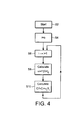
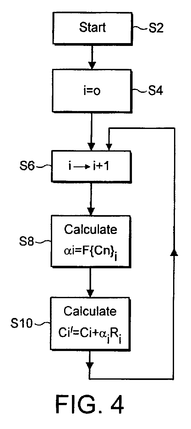
- ⁇ Cn ⁇ i a set of unmodified wavelet coefficients excluding Ci, which set may vary with i, that is respective values of ⁇ i are functions F of respective sets ⁇ Cn ⁇ i . This is shown as step S8 in Figure 4.
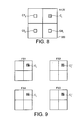
- the coefficients ⁇ Cn ⁇ i of the set may be in the same wavelet band as Ci or may be in different bands from Ci and from each other as described below with reference to Figure 8.
- the coefficients are in the same band as Ci, they are preferably in a window adjacent Ci.
- the set comprises N coefficients Ci-1 to Ci-N as shown in Figure 3 and the embodiment will be described in the following with reference to that.
- N of coefficients may vary with Ci; thus for generality N is denoted as Ni.
- the function F may be any suitable function.
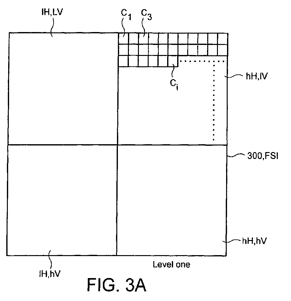
- Figure 3A is a map of wavelet coefficients in a frame store 300, the coefficients being in level 1 of a wavelet transform.
- the coefficients Ci are modified only in the upper horizontal hH, IV and upper vertical 1H, hV bands to embed the watermark.
- coefficients in other bands and/or in other levels may be modified to embed a watermark. In the following only band hH, IV is considered.
- the wavelet coefficients are stored in the frame store 300 (also denoted FS1 in Figure 2) and in this example are stored as shown in Figure 3A grouped in the bands.
- the coefficients are serially ordered. For example they may be serially ordered by a raster scan thereof. Other scanning patterns are known.
- the set ⁇ Cn ⁇ i consists of the Ni coefficients Ci-1 to Ci-Ni preceding coefficient Ci on the same line, up to a maximum of for example M most recent coefficients.
- ⁇ i is defined individually for each coefficient Ci to be modified. In the example above it is defined by the set of Ni unmodified coefficients preceding Ci.
- ⁇ i is adapted to the image such that image degradation can be minimised.
- this allows ⁇ i to be recalculated from the watermarked image coefficients, after those have been restored to their original values. This improves the accuracy of restoring the original image.
- the illustrative procedure for calculating Ci' is as follows:- The calculation procedure starts at step S2. At step S4, i is initialised with value 0. At step S6, i is incremented by 1 to calculate ⁇ 1 at step S8 for coefficient C1'. At step S10 the value of modified coefficient C1' is calculated. The procedure then reverts to step S6 and i is incremented. The procedure continues until all coefficients have been modified.
- the watermark decoder 140 receives the watermarked image I' and outputs the restored UMID.
- the watermark decoder 140 comprises a wavelet transformer 310, a reference pseudo-random sequence (PRBS) generator 320, a correlator 330, a selector 340 and a error correction coding decoder 350.
- PRBS generated by the generator 320 is identical to that generated by the PRBS generator 220 of Figure 2 and converted by a data converter (not shown ) to values +1 and -1 as described above.
- the wavelet transformer 310 receives the watermarked image I' and, in known manner, outputs the modified wavelet coefficients Ci'.
- the correlator 330 receives the reference pseudo-random sequence PRBS having symbols Pi of values +1 and -1 from the pseudo-random sequence generator 320, and the wavelet coefficients Ci' and outputs a watermark image bit correlation sequence 335.
- the watermarked image bit correlation sequence is determined in the following way.
- the modified wavelet coefficients Ci' Ci+ ⁇ i R i where R i are bits of PRBS modulated by error-correction encoded bits Wj of UMID. In the example given above there are 511 bits Wj. Each bit Wj modulates L bits of PRBS. There are JL bits in the modulated PRBS.
- the correlation sequence 335 is received by the selector 340 which outputs an uncorrected UMID 345.
- the selector 340 outputs a bit value "1" for a value of S' greater than 0 and a bit value "0" for S' less than or equal to 0.
- the error correction code decoder 350 receives the uncorrected UMID 345 and in known manner outputs the restored UMID 145.
- the reference PRBS Pi is synchronised with the modulated PRBS in the watermarked image.
- a synchroniser (not shown) is used. Such synchronisation is known in the art.
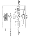
- the watermark remover 130 receives the restored UMID 145, and the watermarked image I' and outputs a restored image I".
- the watermark remover 130 comprises a pseudo-random sequence generator 420 for generating a reference pseudo-random sequence Pi identical to that produced by generators 220 and 320, a spread spectrum signal generator 430 which produces, via a data converter 425, a restored watermark Ri' having bit values +1 and -1 from the restored UMID 145 and the pseudo-random sequence Pi.
- the reference sequence Pi is synchronised with the modulated sequence in the watermarked image in known manner.
- the restored wavelet coefficients C are fed to an inverse wavelet transformer 450 which outputs the restored image I".
- ⁇ i is calculated in the embedder as described above in the section Calculating ⁇
- the estimator 460 of the remover of Figure 6 recalculates ⁇ in analogous manner from coefficients Ci which have been restored to their original values.
- the calculation procedure starts at step S5.
- i is initialised to 0.
- i is incremented by 1 to calculate ⁇ 1 at step S11 for coefficient C1'.
- the original value C1 is calculated from coefficients C1'.
- the procedure then reverts to step S9 and i is incremented. The procedure continues until all coefficients Ci' have been restored to their original values Ci.
- the coefficients from which the value of ⁇ i is calculated may be in different bands to the related coefficient Ci which is to be modified or restored to its original value.
- the set of coefficients ⁇ Cn ⁇ i used to calculate ⁇ i of band hH, IV may be in the other bands.
- the set ⁇ Cn ⁇ i is shown as including coefficients C1i, C2i and C3i which are at positions related to the position of coefficient Ci. In this way, image properties in other bands are taken into account in calculating ⁇ i to ensure that the watermark is imperceptible.
- the coefficients C1i, C2i and C3i used to modify or restore Ci may be coefficient which are never modified. That can be done by modifying only coefficients in one or more bands such as hH, IV and leaving the coefficients in other bands unmodified. Alternatively at least some of the coefficients C1i, C2i and C3i used to modify or restore Ci may be modified. That can be done by storing the coefficients in a frame store 300 as shown in Figure 3 or 8 and by reading out coefficients in an order which allows the procedures of Figures 4 and 7 to be followed.
- the PRBS has a length of L J where J is the number of bits in a UMID.
- each bit Wj of the UMID modulates a section of length L of the PRBS. Instead, it may have a length of L bits and be repeated for each bit j of the UMID.
- the foregoing embodiment calculates ⁇ i using unmodified coefficients.
- ⁇ is calculated using modified coefficients or a combination of modified and unmodified coefficients.
- the coefficients Ci are serially ordered.
- the coefficients used to calculate ⁇ i for coefficient Ci are coefficients preceding i on the serial order.
- frames stores FS1, FS2, FS3 and FS4 are provided in the wavelet transformer 210, the inverse wavelet transformer 250, the wavelet transformer 410 and the inverse wavelet transformer 450.
- Frame stores FS1 and FS4 store unmodified coefficients.
- Frame stores FS2 and FS3 store modified coefficients C'i.
- coefficients Ci in store FS1 are modified, they are stored in FS2 as coefficients Ci '.
- modified coefficients C i ' are available to calculate ⁇ i.
- the set ⁇ Cn ⁇ i used to calculate ⁇ i for modifying coefficient C i may comprise modified coefficients C' preceding C i optionally together with unmodified coefficients C preceding C i .
- a set ⁇ Cn ⁇ i may have any convenient shape. Where ⁇ i is calculated only from coefficients preceding C i , the set may consist of coefficients immediately preceding C i . Where the coefficients are raster scanned to serially order them, the set may consist of coefficients on the same scanning line as C i . Alternatively, it may consist of coefficients on that line and a preceding line. Other shapes are possible.
- FIG 10 illustrates a system, in this example a watermarking system, for embedding a watermark onto an image I and for recovering and removing it from the image.
- the watermarking system comprises: a source 110 of the image I;. a sub-system A for applying the watermark; a sub-system B for detecting and removing the watermark; a channel C linking the sub-systems A and B; and a database D.
- the subsystem A applies the watermark to the image.
- the watermarked image is transmitted via the channel C to the subsystem B where the watermark is detected and removed. It is desired to restore the original image in the subsystem B with no degradation.
- the watermark is removed from the image by a remover 130 and the thus restored image is compared with the original image I to detect differences and the locations within the image of the differences.
- the database D stores the locations of differences and correction data which may be values of the original image at those locations or the differences.
- the subsystem B detects and removes the watermark to produce a substantially restored image. The removal process is the same as at the subsystem A.
- the locations of corrections and the corrections are read from the database and the corrections applied to the restored image to correct it.
- each image is identified by an identifier which is used to access the relevant data in the database.
- the identifier is a UMID.
- UMIDs are described in the section UMIDs below.
- the watermark comprises the UMID.
- the image is transformed by a wavelet transform. Wavelet transforms are discussed in the section Wavelets below. In the example of Figure 1 wavelet coefficients are compared to determine the said differences.
- the source 110 produces a spatial domain image I.
- a comparator 125 compares the restored coefficients Ci" with the original coefficients Ci to determine any differences and the locations thereof.
- the differences and locations i are stored in the database D as correction data together with the UMID generated by generator 115.
- the coefficients Ci' produced by the embedder 120 are inverse transformed (T -1 ) and applied to the channel C.
- the subsystem B receives the watermarked image from the channel C.
- a transformer T recreates the coefficients Ci'.
- the UMID is detected and removed by a detector and remover 127.
- the detected UMID is used to access the correction data in the data base and the correction data is applied to the image coefficients Ci" in a corrector 129 to restore the original coefficients Ci which may be inverse transformed (T -1 )to restore the original image I.
- ⁇ is a fixed predetermined value. Using a fixed predetermined value of ⁇ facilitates removal of the watermark.
- the channel C is preferably "lossless":
- the second example is identical to the first except that a channel emulator 121 is provided between the embedder 120 and remover 130.
- the emulator applies, to the output of the embedder, a channel emulator function emulating the effect of channel C on the output of the embedder.
- the channel emulation 121 emulates the channel C. Thus errors introduced by the channel C can be detected and corrections stored in the database D.
- Figure 11 is identical to Figure 2 described above except that it has a connection supplying the wavelet coefficients Ci to the comparator 125 of Figure 10.
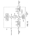
- Figure 12 is identical to Figure 6 above except it has a connection supplying the restored coefficients to the comparator 125 of Figure 10. Thus no further description is needed of Figures 11 and 12.
- Wavelets are well known and are described in for example " A Really Friendly Guide to Wavelets " by C Valens, 1999 and available at http://perso.wanadoo.fr/polyvalens/clemens/wavelets/wavelets.html.
- Valens shows that the discrete wavelet transform can be implemented as an iterated filter bank as used in sub-band coding, with scaling of the image by a factor of 2 at each iteration.
- a spatial domain image is applied to a set of high pass HP and low pass LP filters.
- the image is filtered horizontally and vertically and, in each direction, scaled down by a factor of 2.
- the low pass image from level 1 is filtered and scaled in the same way as in level 1.
- the filtering and scaling may be repeated in subsequent levels 3 onwards.
- Figure 10 is a representation normal in the art. At level one the image is spatially filtered into four bands: the lower horizontal and vertical band. lH 1 , lV 1 ; the upper horizontal band hH 1 , lV 1 ; the upper vertical band lH 1 , hV 1 ; and the upper horizontal and vertical band, hH 1 , hV 1 .
- the lower horizontal and vertical band, lH 1 , lV 1 is filtered and scaled into the lower horizontal and vertical band, lH 2 , lV 2 ; the upper horizontal band hH 2 , lV 2 ; the upper vertical band lH 2 , hV 2 ; and the upper horizontal and vertical band, hH 2 , hV 2
- the lower horizontal and vertical band, lH 2 , lV 2 is further filtered and scaled.
- the UMID or Unique Material Identifier is described in SMPTE Journal March 2000. Referring to Figure 15 an extended UMID is shown. It comprises a first set of 32 bytes of basic UMID and a second set of 32 bytes of signature metadata.
- the first set of 32 bytes is the basic UMID.
- the components are:
- the second set of 32 bytes of the signature metadata as a set of packed metadata items used to create an extended UMID comprises the basic UMID followed immediately by signature metadata which comprises:
- the first 12 bytes of the UMID provide identification of the UMID by the registered string value defined in table 1.
- Specification of the UMID Universal Label Byte No. Description Value (hex) 1 Object Identifier 06h 2 Label size 0Ch 3
- Class Identification and location 01h 10
- Sub-class Globally Unique Identifiers 01h 11
- Type UMID (Picture, Audio, Data, Group) 01, 02, 03, 04h 12
- Type Number creation method XXh
- table 1 may be changed: the values given are examples. Also the bytes 1-12 may have designations other than those shown by way of example in the table. Referring to the Table 1, in the example shown byte 4 indicates that bytes 5-12 relate to a data format agreed by SMPTE. Byte 5 indicates that bytes 6 to 10 relate to "dictionary" data. Byte 6 indicates that such data is "metadata" defined by bytes 7 to 10. Byte 7 indicates the part of the dictionary containing metadata defined by bytes 9 and 10. Byte 10 indicates the version of the dictionary. Byte 9 indicates the class of data and Byte 10 indicates a particular item in the class.
- bytes 1 to 10 have fixed preassigned values. Byte 11 is variable.
- the bytes 1 to 10 of the label of the UMID are fixed. Therefore as shown in Figure 16 they may be replaced by a 1 byte 'Type' code T representing the bytes 1 to 10.
- the type code T is followed by a length code L. That is followed by 2 bytes, one of which is byte 11 of Table 1 and the other of which is byte 12 of Table 1, an instance number (3 bytes) and a material number (16 bytes).
- the material number may be followed by the signature metadata of the extended UMID and/or other metadata.
- the last (12th) byte of the 12 byte label identifies the methods by which the material and instance numbers are created. This byte is divided into top and bottom nibbles where the top nibble defines the method of Material number creation and the bottom nibble defines the method of Instance number creation.
- the Length is a 1-byte number with the value '13h' for basic UMIDs and '33h' for extended UMIDs.
- the Instance number is a unique 3-byte number which is created by one of several means defined by the standard. It provides the link between a particular 'instance' of a clip and externally associated metadata. Without this instance number, all material could be linked to any instance of the material and its associated metadata.
- An Instance number is primarily used to identify associated metadata related to any particular instance of a clip.
- the 16-byte Material number is a non-zero number created by one of several means identified in the standard. The number is dependent on a 6-byte registered port ID number, time and a random number generator.
- Any component from the signature metadata may be null-filled where no meaningful value can be entered. Any null-filled component is wholly null-filled to clearly indicate a downstream decoder that the component is not valid.
- the date-time format is 8 bytes where the first 4 bytes are a UTC (Universal Time Code) based time component.
- the time is defined either by an AES3 32-bit audio sample clock or SMPTE 12M depending on the essence type.
- the second 4 bytes define the date based on the Modified Julian Data (MJD) as defined in SMPTE 309M. This counts up to 999,999 days after midnight on the 17th November 1858 and allows dates to the year 4597.
- JD Modified Julian Data
- the spatial co-ordinate value consists of three components defined as follows:
- the Altitude value is expressed as a value in metres from the centre of the earth thus allowing altitudes below the sea level.
- the Country code is an abbreviated 4-byte alpha-numeric string according to the set defined in ISO 3166. countries which are not registered can obtain a registered alpha-numeric string from the SMPTE Registration Authority.
- the Organisation code is an abbreviated 4-byte alpha-numeric string registered with SMPTE.
- Organisation codes have meaning only in relation to their registered Country code so that Organisation codes can have the same value in different countries.
- the User code is a 4-byte alpha-numeric string assigned locally by each organisation and is not globally registered. User codes are defined in relation to their registered Organisation and Country codes so that User codes may have the same value in different organisations and countries.
Landscapes
- Engineering & Computer Science (AREA)
- Multimedia (AREA)
- Signal Processing (AREA)
- Physics & Mathematics (AREA)
- General Physics & Mathematics (AREA)
- Theoretical Computer Science (AREA)
- Editing Of Facsimile Originals (AREA)
- Image Processing (AREA)
- Television Systems (AREA)
- Storage Device Security (AREA)
Abstract

Description
The calculation procedure starts at step S2. At step S4, i is initialised with
if αi> αTH it is reduced to αTH, where αTH is an upper threshold.
If |Cn|>CTH then Cn is not included in the calculation of αi,; or
if |Cn| >CTH, then Cn is clipped to (Cn/|Cn|)CTH

if αi> αTH it is reduced to αTH, where αTH is an upper threshold.
If |Cn|>CTH then Cn is not included in the calculation of αi; or
if |Cn|>CTH, then Cn is clipped to (Cn/|Cn|)CTH.
- A 12-byte Universal Label to identify this as a SMPTE UMID. It defines the type of material which the UMID identifies and also defines the methods by which the globally unique Material and locally unique Instance numbers are created.
- A 1-byte length value to define the length of the remaining part of the UMID.
- A 3-byte Instance number which is used to distinguish between different 'instances' of material with the same Material number.
- A 16-byte Material number which is used to identify each clip. Each Material number is the same for related instances of the same material.
- An 8-byte time/date code identifying the time and date of the Content Unit creation.
- A 12-byte value which defines the spatial co-ordinates at the time of Content Unit creation.
- 3 groups of 4-byte codes which register the country, organisation and user codes
| Specification of the UMID Universal Label | |||
| Byte No. | Description | Value (hex) | |
| 1 | | 06h | |
| 2 | | 0Ch | |
| 3 | Designation: | 2Bh | |
| 4 | Designation: SMPTE | 34h | |
| 5 | Registry: Dictionaries | 01h | |
| 6 | Registry: Metadata Dictionaries | 01h | |
| 7 | Standard: | 01h | |
| 8 | Version number | 01h | |
| 9 | Class: Identification and | 01h | |
| 10 | Sub-class: Globally Unique Identifiers | 01h | |
| 11 | Type: UMID (Picture, Audio, Data, Group) | 01, 02, 03, 04h | |
| 12 | Type: Number creation method | XXh |
- Altitude: 8 decimal numbers specifying up to 99,999,999 metres.
- Longitude: 8 decimal numbers specifying East/West 180.00000 degrees (5 decimal places active).
- Latitude: 8 decimal numbers specifying North/South 90.00000 degrees (5 decimal places active).
Claims (62)
- A method of embedding data in material, the method comprising the steps of:producing transform coefficients Ci representing a transform of the material, andcombining the coefficients Ci with data symbols Ri to produce modified coefficients Ci' wherethe method further comprising determining αi for each unmodified coefficient Ci as a function F{Cn}i of a predetermined set {Cn}i of transform coefficients Cn which set excludes the coefficient Ci wherein the coefficients are serially ordered and the coefficients Cn are coefficients preceding coefficient Ci.
- A method according to claim 1 wherein the coefficients of the set {Cn}i vary with i.
- A method according to claim 1 or 2, wherein the number Ni of coefficients in the set {Cn}i varies with i.
- A method according to claim 1, 2 or 3, wherein the coefficients of the set {Cn}i have a predetermined positional relationship with the coefficient Ci to be modified.
- A method according to claim 1, 2, 3 or 4, wherein the coefficients represent a spatial frequency transform of the material.
- A method according to claim 1, 2, 3 or 4, wherein the coefficients represent a wavelet transform of the material.
- A method according to claim 6, wherein the transform produces coefficients Ci in a plurality of bands.
- A method according to claim 7, wherein the transform coefficients forming the set {Cn}i are all in the same band.
- A method according to claim 7, wherein the transform coefficients forming the set {Cn}i are in a plurality of bands.
- A method according to any preceding claim wherein the said function F{Cn}i is such that
where Ni is the number of coefficients Cn in set i. - A method according to any preceding claim, wherein the said data symbols Ri are of a pseudo random symbol sequence having symbols Pi modulated by data Wj to be embedded.
- Apparatus for embedding data in material, comprisinga transformer for producing transform coefficients Ci representing a transform of the material, anda combiner for combining the coefficients Ci with data symbols Ri to produce modified coefficients Ci' wherethe apparatus further comprisinga calculator for calculating αi for each unmodified coefficient Ci as a function F{Cn}i of a predetermined set {Cn}i of transform coefficients Cn which set excludes the coefficient Ci, wherein the coefficients are serially ordered and the coefficients Cn are coefficients preceding coefficient Ci.
- Apparatus according to claim 12, wherein the coefficients of the set {Cn}i vary with i.
- Apparatus according to claim 12, or 13, wherein the unmodified coefficients of the set {Cn}i have a predetermined positional relationship with the coefficient Ci to be modified.
- Apparatus according to claim 12, 13 or 14, wherein the coefficients represent a spatial frequency transform of the material.
- Apparatus according to claim 12, 13, or 14, wherein the coefficients represent a wavelet transform of the material
- Apparatus according to claim 16, wherein the transformer produces coefficients Ci in a plurality of frequency bands.
- Apparatus according to claim 17, wherein the transform coefficients forming the set {Cn}i are all in the same band.
- Apparatus according to claim 18, wherein the transform coefficients forming the set {Cn}i are in a plurality of bands.
- Apparatus according to any one of claims 12 to 19, wherein the said function F{Cn}i is such that
where Ni is the number of coefficients Cn in set i. - A method or apparatus according to any preceding claim, wherein the data is imperceptibly embedded in the other material.
- A method or apparatus according to any preceding claim, wherein the set {Cn}i consists of unmodified coefficients.
- A method or apparatus according to any one of claims 1 to 21, wherein the set {Cn}i consists of modified coefficients preceding Ci where the coefficients are serially ordered.
- A method or apparatus according to any one of claims 1 to 21, wherein the set {Cn}i comprises at least one modified coefficient and at least one unmodified coefficient.
- A method of removing data embedded in material according to the method of any one of claims 1 to 12, the detecting method comprising:determining the values of the data symbols Ri;calculating, for each modified coefficient Ci', the value of the said function F{Cn}i of the corresponding set {Cn}i of coefficients Cn to determine αi; andfor each modified coefficient Ci', subtracting therefrom αi.Ri to restore the unmodified coefficient value Ci, wherein the coefficients are serially ordered and the said set {Cn}i consists of modified coefficients preceding coefficient Ci.
- A method according to claim 25, wherein the said set {Cn}i consists of restored coefficients Ci and comprising the further step of using a restored coefficient Ci as a coefficient of another set {Cn}j of coefficients for restoring another coefficient Cj.
- Apparatus according to claim 25 or 26, wherein the said set {Cn}i comprises at least one modified coefficient and at least one restored coefficient, the coefficients preceding C'i.
- A method according to any one of claims 25 to 27, wherein the step of determining the values of the data bits Wj embedded in material according to the method of claim 11, comprises correlating a reference pseudo random symbol sequence with the modified coefficients Ci' and decoding the correlation values to determine the data Wj modulating the pseudo random sequence and remodulating the reference sequence with the said data to restore Ri.
- Apparatus for removing data embedded in material according to the method of any one of claims 1 to 11, the apparatus comprising:a processor for determining the values of the symbols Ri;a calculator for calculating, for each modified coefficient Ci', the value of the said function F{Cn}i of the corresponding set {Cn}i of coefficients Cn to determine αi; anda subtractor which, for each modified coefficient Ci', subtracts therefrom αi.Ri to restore the unmodified coefficient value Ci, which thereby becomes available for use as an unmodified coefficient of another set {Cn}i of unmodified coefficients Cn for restoring another coefficient Ci', wherein the coefficients are serially ordered and the said set {Cn}i consists of coefficients preceding coefficient Ci.
- Apparatus according to claim 29, wherein the said set {Cn}i consists of restored coefficients Ci and comprising the further step of using a restored coefficient Ci as a coefficient of another set {Cn}i+1 of coefficients for restoring another coefficient Ci+1.
- Apparatus according to claim 30, wherein the said set {Cn}i consists of modified coefficients preceding coefficient Ci.
- Apparatus according to claim 30, wherein the said set {Cn}i comprises at least one modified coefficient and at least one restored coefficient, the coefficients preceding C'i.
- Apparatus according to claim 29, 30, 31 or 32, wherein the means for determining the values of the data bits Wj embedded in the material according to the method of claim 12, comprises a correlator for correlating a reference pseudo random symbol sequence with the modified coefficients Ci', a decoder for decoding the correlations to determine the data Wj modulating the modulated sequence and a modulator for remodulating the reference sequence with the said data to restore Ri.
- A computer program product arranged to carry out the method of any one of claims 1 to 11 when run on a computer.
- A computer program product arranged to carry out the method of any one of claims 25 to 30 when run on a computer.
- A method or apparatus according to any preceding claim, wherein the material is video material.
- A method or apparatus according to any one of claims 1 to 35, wherein the material is audio material.
- A method or apparatus according to any one of claims 1 to 35, wherein the material is audio/visual material.
- A method of removing data embedded in material comprising the steps of:receiving material in which data is embedded;accessing an information store storing information enabling the data to be removed; andremoving the said data using the enabling data accessed from the store.
- A method comprising the steps of:embedding data in material; andstoring, in an information store, information for enabling the data to be removed from the material.
- Apparatus for removing data embedded in material comprising:an input for receiving material in which data is embedded;an information store for storing information enabling the data to be removed; anda remover arranged to remove the said data using the enabling data accessed from the store.
- Apparatus comprising:an embedder for embedding data in material;a store for storing information for enabling the data to be removed from the material; anda generator for generating the enabling information when the said data is embedded in the material.
- A method comprising the steps of:embedding data in first material to produce second material in which the data is embedded;removing the data from the second material to produce recovered material;comparing the first and recovered material to determine any differences and locations of differences therebetween; andstoring corrections which correct the said differences and data identifying the said locations in the first material at which the differences occur.
- A method according to claim 43, further comprising applying a channel emulation to the second material, wherein the removing step produces recovered material from the second material to which the emulation function has been applied.
- A method according to claim 43 or 44, wherein the storing step comprises storing, as the said corrections, the values of the first material which values occur at the said locations in the first material.
- A method according to claim 44 or 45, wherein the storing step comprises storing the said differences.
- A method according to claim 43, 44, 45 or 46, further comprising storing identification data which identifies the said material.
- A method according to claim 43, 44, 45, 46 or 47, wherein the said identification data comprises an identifier which identifies the second material.
- A method of removing data embedded in material, the data being embedded in the material according to the method of any one of claims 5 to 10, the removing method comprising the steps of:removing the data from the said second material to produce recovered material;retrieving the said corrections and locations from a store storing the said corrections which correct the said differences and the said data identifying the said locations in the first material at which the differences occur; andusing the said retrieved corrections to correct the recovered material at the said locations identified by the identifying data.
- A method according to claim 49, wherein the using step comprises replacing the values of the recovered material at the said locations identified by the identifying data by the stored values of the first material at the said locations.
- A method according to claim 49, wherein the using step comprises correcting the values of the recovered material at the said locations using the said stored differences.
- A method according to claim 49, 50 or 51, further comprising the step of determining the identifier of the second material and retrieving from the said store the corrections and locations associated with the identified material.
- Apparatus comprising:an embedder for embedding data in first material to produce second material in which data is embedded;a remover for removing the data from the second material to produce recovered material;a comparator for comparing the first and recovered material to determine the differences, and locations of differences, therebetween; anda store for storing data identifying the said locations and corrections which correct the said differences.
- Apparatus according to claim 35, further comprising a channel emulator between the embedder and remover.
- Apparatus for removing data from material the removing apparatus comprising:a remover for removing the data from the said second material to produce recovered material;a deriver for deriving the said corrections and identifying data from the said store; anda corrector arranged to use the stored corrections to correct the recovered material at the said locations identified by the identifying data.
- A system comprising embedding apparatus according to claim 53 or 54, and removing apparatus according to claim 55 linked by a channel.
- An apparatus or method according to any one of claims 39 to 56, wherein the said material is video material.
- An apparatus or method according to any one of claims 39 to 56, wherein the said material is audio material.
- An apparatus or method according to any one of claims 39 to 56, wherein the said material is audio-visual material
- An apparatus or method according to anyone of claims 39 to 59, wherein the said data includes a UMID.
- A computer program product arranged to carry out the method of any one of claims 39 to 47 and 57 to 60 when run on a computer.
- A computer program product arranged to carry out the method of any one of claims 49 to 52 and 57 to 60 when run on a computer.
Applications Claiming Priority (4)
| Application Number | Priority Date | Filing Date | Title |
|---|---|---|---|
| GB0029855 | 2000-12-07 | ||
| GBGB0029855.4A GB0029855D0 (en) | 2000-04-05 | 2000-12-07 | Embedding data in material and removing the embedded data |
| GB0029860 | 2000-12-07 | ||
| GB0029860A GB0029860D0 (en) | 2000-12-07 | 2000-12-07 | Embedding data in material |
Publications (2)
| Publication Number | Publication Date |
|---|---|
| EP1215880A2 true EP1215880A2 (en) | 2002-06-19 |
| EP1215880A3 EP1215880A3 (en) | 2003-08-13 |
Family
ID=26245397
Family Applications (1)
| Application Number | Title | Priority Date | Filing Date |
|---|---|---|---|
| EP01310099A Withdrawn EP1215880A3 (en) | 2000-12-07 | 2001-12-03 | Embedding data in material |
Country Status (3)
| Country | Link |
|---|---|
| US (2) | US7088843B2 (en) |
| EP (1) | EP1215880A3 (en) |
| JP (1) | JP4094284B2 (en) |
Cited By (3)
| Publication number | Priority date | Publication date | Assignee | Title |
|---|---|---|---|---|
| GB2390503A (en) * | 2002-07-04 | 2004-01-07 | Sony Uk Ltd | Detecting data using a reduced-bandwidth version of suspect material |
| EP1471722A3 (en) * | 2003-04-25 | 2005-07-06 | Kabushiki Kaisha Toshiba | Image processing system |
| CN108492238A (en) * | 2018-03-07 | 2018-09-04 | 小明太极(湖北)国漫文化有限公司 | Blind watermatking embedding grammar and extracting method |
Families Citing this family (21)
| Publication number | Priority date | Publication date | Assignee | Title |
|---|---|---|---|---|
| GB2369949B (en) * | 2000-12-07 | 2005-03-16 | Sony Uk Ltd | Embedding data in material |
| US7254249B2 (en) * | 2001-03-05 | 2007-08-07 | Digimarc Corporation | Embedding location data in video |
| US7061510B2 (en) | 2001-03-05 | 2006-06-13 | Digimarc Corporation | Geo-referencing of aerial imagery using embedded image identifiers and cross-referenced data sets |
| US7249257B2 (en) * | 2001-03-05 | 2007-07-24 | Digimarc Corporation | Digitally watermarked maps and signs and related navigational tools |
| US7006662B2 (en) | 2001-12-13 | 2006-02-28 | Digimarc Corporation | Reversible watermarking using expansion, rate control and iterative embedding |
| US7187780B2 (en) * | 2001-12-13 | 2007-03-06 | Digimarc Corporation | Image processing methods using reversible watermarking |
| US8059815B2 (en) * | 2001-12-13 | 2011-11-15 | Digimarc Corporation | Transforming data files into logical storage units for auxiliary data through reversible watermarks |
| US7515730B2 (en) * | 2001-12-13 | 2009-04-07 | Digimarc Corporation | Progressive image quality control using watermarking |
| AU2002357259A1 (en) * | 2001-12-13 | 2003-07-09 | Digimarc Corporation | Reversible watermarking |
| US7190805B2 (en) * | 2002-04-30 | 2007-03-13 | Hewlett-Packard Development Company, L.P. | Method of and system for edge watermarking of an image |
| FR2849980B1 (en) * | 2003-01-15 | 2005-04-08 | Medialive | METHOD FOR THE DISTRIBUTION OF VIDEO SEQUENCES, DECODER AND SYSTEM FOR THE IMPLEMENTATION OF THIS PRODUCT |
| FR2850515B1 (en) * | 2003-01-23 | 2005-07-01 | Medialive | ADAPTIVE AND PROGRESSIVE METHOD AND SYSTEM FOR SECURELY DISTRIBUTING FIXED IMAGES CODED IN WAVELET |
| FR2853786B1 (en) * | 2003-04-11 | 2005-08-05 | Medialive | METHOD AND EQUIPMENT FOR DISTRIBUTING DIGITAL VIDEO PRODUCTS WITH A RESTRICTION OF CERTAIN AT LEAST REPRESENTATION AND REPRODUCTION RIGHTS |
| TWI228376B (en) * | 2003-12-23 | 2005-02-21 | Ind Tech Res Inst | Watermark encoding method and recording medium thereof |
| US7668334B2 (en) * | 2004-07-02 | 2010-02-23 | Digimarc Corp | Conditioning imagery to better receive steganographic encoding |
| GB2421136A (en) * | 2004-12-09 | 2006-06-14 | Sony Uk Ltd | Detection of code word coefficients in a watermarked image |
| US8249350B2 (en) | 2006-06-30 | 2012-08-21 | University Of Geneva | Brand protection and product autentication using portable devices |
| US8055708B2 (en) * | 2007-06-01 | 2011-11-08 | Microsoft Corporation | Multimedia spaces |
| US10943030B2 (en) | 2008-12-15 | 2021-03-09 | Ibailbonding.Com | Securable independent electronic document |
| US9538040B2 (en) * | 2011-12-16 | 2017-01-03 | University Of Maryland, College Park | Active sensing for dynamic spectrum access |
| FR2990783B1 (en) * | 2012-05-21 | 2014-05-02 | St Microelectronics Rousset | METHOD FOR PROCESSING A NON-VOLATILE MEMORY, ESPECIALLY A MEMORY OF THE EEPROM TYPE, FOR STORING AND EXTRACTING INFORMATION, AND CORRESPONDING MEMORY DEVICE |
Family Cites Families (26)
| Publication number | Priority date | Publication date | Assignee | Title |
|---|---|---|---|---|
| US5721788A (en) * | 1992-07-31 | 1998-02-24 | Corbis Corporation | Method and system for digital image signatures |
| JPH07212712A (en) | 1993-10-29 | 1995-08-11 | Eastman Kodak Co | Method and equipment for adding and deleting digital watermark in hierarchical picture memory and fetch system |
| US5530759A (en) * | 1995-02-01 | 1996-06-25 | International Business Machines Corporation | Color correct digital watermarking of images |
| CA2184949C (en) * | 1995-09-28 | 2000-05-30 | Ingemar J. Cox | Secure spread spectrum watermarking for multimedia data |
| US5689587A (en) * | 1996-02-09 | 1997-11-18 | Massachusetts Institute Of Technology | Method and apparatus for data hiding in images |
| IL118643A (en) | 1996-06-12 | 1999-12-22 | Aliroo Ltd | System for protecting digital images provided to a recipient |
| US5889868A (en) * | 1996-07-02 | 1999-03-30 | The Dice Company | Optimization methods for the insertion, protection, and detection of digital watermarks in digitized data |
| US6037984A (en) | 1997-12-24 | 2000-03-14 | Sarnoff Corporation | Method and apparatus for embedding a watermark into a digital image or image sequence |
| US6332030B1 (en) * | 1998-01-15 | 2001-12-18 | The Regents Of The University Of California | Method for embedding and extracting digital data in images and video |
| JP4313873B2 (en) * | 1998-01-30 | 2009-08-12 | キヤノン株式会社 | Electronic device and data processing method |
| US6064764A (en) | 1998-03-30 | 2000-05-16 | Seiko Epson Corporation | Fragile watermarks for detecting tampering in images |
| US6154571A (en) | 1998-06-24 | 2000-11-28 | Nec Research Institute, Inc. | Robust digital watermarking |
| US6694040B2 (en) * | 1998-07-28 | 2004-02-17 | Canon Kabushiki Kaisha | Data processing apparatus and method, and memory medium |
| US6704431B1 (en) | 1998-09-04 | 2004-03-09 | Nippon Telegraph And Telephone Corporation | Method and apparatus for digital watermarking |
| EP2219152B1 (en) | 1999-01-25 | 2018-07-04 | Nippon Telegraph And Telephone Corporation | Digital watermark embedding and detecting method |
| US7031491B1 (en) * | 1999-04-09 | 2006-04-18 | Canon Kabushiki Kaisha | Method for determining a partition in order to insert a watermark, and associated insertion and decoding methods |
| US6785815B1 (en) * | 1999-06-08 | 2004-08-31 | Intertrust Technologies Corp. | Methods and systems for encoding and protecting data using digital signature and watermarking techniques |
| EP1098522A1 (en) | 1999-11-05 | 2001-05-09 | Sony United Kingdom Limited | Method and apparatus for identifying a digital signal with a watermark |
| GB0029855D0 (en) * | 2000-04-05 | 2001-01-24 | Sony Uk Ltd | Embedding data in material and removing the embedded data |
| JP2002062888A (en) * | 2000-08-21 | 2002-02-28 | Matsushita Electric Ind Co Ltd | Electronic music processing device, electronic music playback device, and electronic music distribution system |
| WO2002017214A2 (en) * | 2000-08-24 | 2002-02-28 | Digimarc Corporation | Watermarking recursive hashes into frequency domain regions and wavelet based feature modulation watermarks |
| US6714683B1 (en) * | 2000-08-24 | 2004-03-30 | Digimarc Corporation | Wavelet based feature modulation watermarks and related applications |
| US6512837B1 (en) * | 2000-10-11 | 2003-01-28 | Digimarc Corporation | Watermarks carrying content dependent signal metrics for detecting and characterizing signal alteration |
| WO2002039714A2 (en) * | 2000-11-08 | 2002-05-16 | Digimarc Corporation | Content authentication and recovery using digital watermarks |
| JP3576993B2 (en) * | 2001-04-24 | 2004-10-13 | 株式会社東芝 | Digital watermark embedding method and apparatus |
| KR100624751B1 (en) * | 2003-04-25 | 2006-09-19 | (주)마크텍 | A method of embedding a watermark in an image and a digital video storage device using the method |
-
2001
- 2001-12-03 EP EP01310099A patent/EP1215880A3/en not_active Withdrawn
- 2001-12-06 US US10/006,294 patent/US7088843B2/en not_active Expired - Fee Related
- 2001-12-07 JP JP2001375050A patent/JP4094284B2/en not_active Expired - Fee Related
-
2005
- 2005-04-11 US US11/103,005 patent/US7203336B2/en not_active Expired - Fee Related
Cited By (4)
| Publication number | Priority date | Publication date | Assignee | Title |
|---|---|---|---|---|
| GB2390503A (en) * | 2002-07-04 | 2004-01-07 | Sony Uk Ltd | Detecting data using a reduced-bandwidth version of suspect material |
| US7194108B2 (en) | 2002-07-04 | 2007-03-20 | Sony United Kingdom Limited | Data processing apparatus and method |
| EP1471722A3 (en) * | 2003-04-25 | 2005-07-06 | Kabushiki Kaisha Toshiba | Image processing system |
| CN108492238A (en) * | 2018-03-07 | 2018-09-04 | 小明太极(湖北)国漫文化有限公司 | Blind watermatking embedding grammar and extracting method |
Also Published As
| Publication number | Publication date |
|---|---|
| JP4094284B2 (en) | 2008-06-04 |
| US7088843B2 (en) | 2006-08-08 |
| US7203336B2 (en) | 2007-04-10 |
| US20050180598A1 (en) | 2005-08-18 |
| US20020118859A1 (en) | 2002-08-29 |
| JP2002314798A (en) | 2002-10-25 |
| EP1215880A3 (en) | 2003-08-13 |
Similar Documents
| Publication | Publication Date | Title |
|---|---|---|
| US7088843B2 (en) | Embedding data in material | |
| US7085396B2 (en) | Embedding data in material | |
| US7181042B2 (en) | Digital authentication with digital and analog documents | |
| US6683966B1 (en) | Watermarking recursive hashes into frequency domain regions | |
| US6771797B2 (en) | Watermarks carrying content dependent signal metrics for detecting and characterizing signal alteration | |
| EP0981903B1 (en) | Watermark detection | |
| US8032758B2 (en) | Content authentication and recovery using digital watermarks | |
| US5835639A (en) | Method for detecting rotation and magnification in images | |
| EP1043687B1 (en) | Method for inserting a watermark and associated decoding method | |
| EP1098522A1 (en) | Method and apparatus for identifying a digital signal with a watermark | |
| Barni et al. | Copyright protection of digital images by embedded unperceivable marks | |
| Bas et al. | Using the fractal code to watermark images | |
| WO2001076253A1 (en) | Watermarked material processing | |
| EP1750426A1 (en) | Methods and apparatus for embedding data and for detecting and recovering embedded data | |
| WO2002019269A2 (en) | A method for encoding and decoding image dependent watermarks | |
| US7127079B2 (en) | Image processing apparatus | |
| US7085395B2 (en) | Apparatus for detecting and recovering data | |
| US7856119B2 (en) | Embedding data in material | |
| US20050144456A1 (en) | Robust digital image watermarking utilizing a Walsh transform algorithm | |
| Liu et al. | DWT-based video data hiding robust to MPEG compression and frame loss | |
| US20020122565A1 (en) | Image processing apparatus | |
| Burdescu et al. | A spatial watermarking algorithm for digital images | |
| GB2369948A (en) | Apparatus for recovering embedded watermark data via correlation sequences |
Legal Events
| Date | Code | Title | Description |
|---|---|---|---|
| PUAI | Public reference made under article 153(3) epc to a published international application that has entered the european phase |
Free format text: ORIGINAL CODE: 0009012 |
|
| AK | Designated contracting states |
Kind code of ref document: A2 Designated state(s): AT BE CH CY DE DK ES FI FR GB GR IE IT LI LU MC NL PT SE TR |
|
| AX | Request for extension of the european patent |
Free format text: AL;LT;LV;MK;RO;SI |
|
| PUAL | Search report despatched |
Free format text: ORIGINAL CODE: 0009013 |
|
| AK | Designated contracting states |
Designated state(s): AT BE CH CY DE DK ES FI FR GB GR IE IT LI LU MC NL PT SE TR |
|
| AX | Request for extension of the european patent |
Extension state: AL LT LV MK RO SI |
|
| 17P | Request for examination filed |
Effective date: 20040128 |
|
| AKX | Designation fees paid |
Designated state(s): DE FR GB |
|
| 17Q | First examination report despatched |
Effective date: 20040325 |
|
| STAA | Information on the status of an ep patent application or granted ep patent |
Free format text: STATUS: THE APPLICATION IS DEEMED TO BE WITHDRAWN |
|
| 18D | Application deemed to be withdrawn |
Effective date: 20100413 |