EP1215875A2 - Thermal scan line bow adjustment in an optical scanning system - Google Patents
Thermal scan line bow adjustment in an optical scanning system Download PDFInfo
- Publication number
- EP1215875A2 EP1215875A2 EP01129127A EP01129127A EP1215875A2 EP 1215875 A2 EP1215875 A2 EP 1215875A2 EP 01129127 A EP01129127 A EP 01129127A EP 01129127 A EP01129127 A EP 01129127A EP 1215875 A2 EP1215875 A2 EP 1215875A2
- Authority
- EP
- European Patent Office
- Prior art keywords
- scan line
- mirror
- bow
- heating element
- optical scanning
- Prior art date
- Legal status (The legal status is an assumption and is not a legal conclusion. Google has not performed a legal analysis and makes no representation as to the accuracy of the status listed.)
- Granted
Links
Images



Classifications
-
- G—PHYSICS
- G02—OPTICS
- G02B—OPTICAL ELEMENTS, SYSTEMS OR APPARATUS
- G02B26/00—Optical devices or arrangements for the control of light using movable or deformable optical elements
- G02B26/08—Optical devices or arrangements for the control of light using movable or deformable optical elements for controlling the direction of light
- G02B26/10—Scanning systems
- G02B26/12—Scanning systems using multifaceted mirrors
- G02B26/125—Details of the optical system between the polygonal mirror and the image plane
- G02B26/126—Details of the optical system between the polygonal mirror and the image plane including curved mirrors
-
- G—PHYSICS
- G02—OPTICS
- G02B—OPTICAL ELEMENTS, SYSTEMS OR APPARATUS
- G02B26/00—Optical devices or arrangements for the control of light using movable or deformable optical elements
- G02B26/08—Optical devices or arrangements for the control of light using movable or deformable optical elements for controlling the direction of light
- G02B26/0816—Optical devices or arrangements for the control of light using movable or deformable optical elements for controlling the direction of light by means of one or more reflecting elements
- G02B26/0825—Optical devices or arrangements for the control of light using movable or deformable optical elements for controlling the direction of light by means of one or more reflecting elements the reflecting element being a flexible sheet or membrane, e.g. for varying the focus
-
- G—PHYSICS
- G02—OPTICS
- G02B—OPTICAL ELEMENTS, SYSTEMS OR APPARATUS
- G02B7/00—Mountings, adjusting means, or light-tight connections, for optical elements
- G02B7/18—Mountings, adjusting means, or light-tight connections, for optical elements for prisms; for mirrors
- G02B7/181—Mountings, adjusting means, or light-tight connections, for optical elements for prisms; for mirrors with means for compensating for changes in temperature or for controlling the temperature; thermal stabilisation
- G02B7/1815—Mountings, adjusting means, or light-tight connections, for optical elements for prisms; for mirrors with means for compensating for changes in temperature or for controlling the temperature; thermal stabilisation with cooling or heating systems
-
- H—ELECTRICITY
- H04—ELECTRIC COMMUNICATION TECHNIQUE
- H04N—PICTORIAL COMMUNICATION, e.g. TELEVISION
- H04N1/00—Scanning, transmission or reproduction of documents or the like, e.g. facsimile transmission; Details thereof
- H04N1/04—Scanning arrangements, i.e. arrangements for the displacement of active reading or reproducing elements relative to the original or reproducing medium, or vice versa
- H04N1/047—Detection, control or error compensation of scanning velocity or position
- H04N1/0473—Detection, control or error compensation of scanning velocity or position in subscanning direction, e.g. picture start or line-to-line synchronisation
-
- H—ELECTRICITY
- H04—ELECTRIC COMMUNICATION TECHNIQUE
- H04N—PICTORIAL COMMUNICATION, e.g. TELEVISION
- H04N1/00—Scanning, transmission or reproduction of documents or the like, e.g. facsimile transmission; Details thereof
- H04N1/04—Scanning arrangements, i.e. arrangements for the displacement of active reading or reproducing elements relative to the original or reproducing medium, or vice versa
- H04N1/113—Scanning arrangements, i.e. arrangements for the displacement of active reading or reproducing elements relative to the original or reproducing medium, or vice versa using oscillating or rotating mirrors
- H04N1/1135—Scanning arrangements, i.e. arrangements for the displacement of active reading or reproducing elements relative to the original or reproducing medium, or vice versa using oscillating or rotating mirrors for the main-scan only
-
- H—ELECTRICITY
- H04—ELECTRIC COMMUNICATION TECHNIQUE
- H04N—PICTORIAL COMMUNICATION, e.g. TELEVISION
- H04N1/00—Scanning, transmission or reproduction of documents or the like, e.g. facsimile transmission; Details thereof
- H04N1/04—Scanning arrangements, i.e. arrangements for the displacement of active reading or reproducing elements relative to the original or reproducing medium, or vice versa
- H04N1/12—Scanning arrangements, i.e. arrangements for the displacement of active reading or reproducing elements relative to the original or reproducing medium, or vice versa using the sheet-feed movement or the medium-advance or the drum-rotation movement as the slow scanning component, e.g. arrangements for the main-scanning
-
- H—ELECTRICITY
- H04—ELECTRIC COMMUNICATION TECHNIQUE
- H04N—PICTORIAL COMMUNICATION, e.g. TELEVISION
- H04N2201/00—Indexing scheme relating to scanning, transmission or reproduction of documents or the like, and to details thereof
- H04N2201/024—Indexing scheme relating to scanning, transmission or reproduction of documents or the like, and to details thereof deleted
- H04N2201/02406—Arrangements for positioning elements within a head
- H04N2201/02439—Positioning method
- H04N2201/02441—Positioning method using screws
-
- H—ELECTRICITY
- H04—ELECTRIC COMMUNICATION TECHNIQUE
- H04N—PICTORIAL COMMUNICATION, e.g. TELEVISION
- H04N2201/00—Indexing scheme relating to scanning, transmission or reproduction of documents or the like, and to details thereof
- H04N2201/04—Scanning arrangements
- H04N2201/047—Detection, control or error compensation of scanning velocity or position
- H04N2201/04753—Control or error compensation of scanning position or velocity
- H04N2201/04758—Control or error compensation of scanning position or velocity by controlling the position of the scanned image area
- H04N2201/0476—Control or error compensation of scanning position or velocity by controlling the position of the scanned image area using an optical, electro-optical or acousto-optical element
- H04N2201/04762—Control or error compensation of scanning position or velocity by controlling the position of the scanned image area using an optical, electro-optical or acousto-optical element using a reflecting element
-
- H—ELECTRICITY
- H04—ELECTRIC COMMUNICATION TECHNIQUE
- H04N—PICTORIAL COMMUNICATION, e.g. TELEVISION
- H04N2201/00—Indexing scheme relating to scanning, transmission or reproduction of documents or the like, and to details thereof
- H04N2201/04—Scanning arrangements
- H04N2201/047—Detection, control or error compensation of scanning velocity or position
- H04N2201/04753—Control or error compensation of scanning position or velocity
- H04N2201/04794—Varying the control or compensation during the scan, e.g. using continuous feedback or from line to line
- H04N2201/04796—Varying the sub-scan control during the main-scan, e.g. for correcting skew, tilt or bow of a scanning beam
Definitions
- This invention relates to the scan line bow in an optical scanning system and, more particularly, to a heating element for adjusting the curvature of a cylindrical mirror, typically the wobble correction mirror, to compensate and correct the scan line bow in an optical scanner or to approximately equalize the scan line bows in a multiple beam optical scanning system.
- a raster output scanner conventionally has a multi-faceted polygon mirror that is rotated about its central axis while an intensity-modulated beam is directed to the rotating polygon at a predetermined angle.
- the light beam is reflected by a facet and thereafter focussed to a "spot" on a photosensitive recording medium.
- the rotation of the polygon causes the spot to scan linearly across the photosensitive medium in a scan direction.
- the photosensitive medium is advanced relatively more slowly than the rate of the scan in a slow scan direction which is orthogonal to the scan direction. In this way, the beam scans the photosensitive medium in a raster scanning pattern.
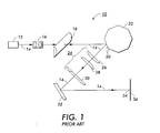
- FIG. 1 wherein there is disclosed a conventional prior art raster scanning system 10.
- a laser diode light source 12 emits a modulated coherent light beam 14 which is collimated by a multi-element optical collimator 16.
- the resulting collimated beam 14 passes through a cross-scan cylindrical lens 18.
- the cylindrical lens 18 focuses the light beam 14 in the sagittal or cross scan plane onto a facet 20 of the rotating multi-faceted polygon mirror 22 while maintaining the collimation of the scan portion of the beam.
- the light beam 14 thus forms a line on the facet 20.
- the light beam 14 is reflected from the facet 20 and the reflected light beam is still collimated in the scan plane and is now diverging in the cross-scan plane.
- the reflected beam 14 then passes through an f-theta scan lens 24 consisting of a negative plano-spherical lens 26, a positive plano-spherical lens 28 and a cross-scan cylindrical lens 30.
- This f-theta scan lens configuration converges the beam 14 in the scan axis.
- the light beam 14 After passing through the f-theta scan lens 24, the light beam 14 is then reflected off a cylindrical wobble correction mirror 32.
- the mirror 32 is positive and cylindrical in the cross-scan plane and flat in the scan plane.
- the wobble mirror converges the previously diverging cross-scan portion of the light beam 14 but allows the converging cross-scan portion of the light beam 14 focused by the f-theta lens 24 to pass through unaffected.
- the reflected beam 14 is focussed onto a scan line 34 on a photosensitive medium 36 such as a photoreceptor.
- a raster scanner typically includes a number of lenses and mirrors to accommodate a specific design. Unavoidable imprecision in the shape and/or mounting of these optical elements will inevitably introduce certain anomalies in the quality of the scan line on the photoreceptor. Also, different errors can be introduced to the light beam by different optical elements of the raster scanner in which case the error is cumulative. One such anomaly is bow.
- Bow is an undesirable character of a scan line when the light beam is offset in the cross-scan direction from the ideal horizontal straight line in the scan direction of the scan line on the recording medium.
- the scan line bow occurs because the magnification of the optical system of the ROS varies across the cross-scan direction as the beam propagates through the optical system.
- FIG. 1 An example of a bow is shown by scan line 50 in Figure 2.
- scan line 50 in Figure 2.
- the two end points of the bowed scan line will bend in an opposite direction relative to the mid-point of the bowed scan line with the scan line deviating relative to a straight, bow free line 52.
- a bow 50 (Figure 2) with the end points of the scan line situated downward is called a frown and a bow 54 ( Figure 3) with the end points of the scan line situated upward is called a smile.
- the scan lines from multiple raster scanners are registered or positioned in parallel lines on the photosensitive medium.
- Another undesirable character with multi-beam scanners is called differential bow. Differential bow happens in multi-beam raster scanners in which the multiple light beams are nominally off-axis relative to each other and relative to the straight bow free scan line.
- Scan line bow arises from multiple beams from a single ROS.
- Scan line bow is a different problem.
- Scan line bow arises in both single and multiple beam ROS's and is the overall curvature of the scan line relative to the ideal of a straight scan line.
- a heating element adjusts the curvature of a cylindrical wobble correction mirror to compensate and correct the scan line bow for an optical scanner.
- a current applied through the heating element along one side of the mirror will cause the mirror to bend vertically for a horizontal beam to adjust the scan line bow for a single beam and approximately equalize the scan line bow for multiple beams.
- a rheostat will vary the current to vary the applied heat to control the amount of bend in the mirror.
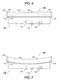
- FIG. 6 wherein there is illustrated a first embodiment of a heating element 100 for adjusting the curvature of a cylindrical mirror 102 in accordance with this invention.
- the cylindrical mirror 102 is typically the wobble correction mirror in the ROS.
- the mirror is fabricated from plastic with a reflective dielectric coating. Alternately, the mirror could be fabricated from glass or metal. Also alternately, the mirror can have a reflective metallic coating.
- the wobble correction mirror is the last optical element in the raster output scanning system before the light beam is focused to a spot on the scan line of the photosensitive medium. Since scan line bow arise from imperfections in the previous optical ROS elements and since the optical effects of the imperfections are cumulative, then the wobble correction mirror is the last, best opportunity to correct for bow of the ROS.
- the mirror is flexibly secured at the horizontal ends 104, 106 by mirror mounts 108, 110.
- the mirror is secured at the horizontal ends to avoid twisting along the long horizontal axis of the mirror but the mirror is capable of bending along its vertical axis, the amount of the bending being adjusted by the heating element 100.
- the heating element 100 has a thin, electrically conductive, nichrome wire 112 along the horizontal length of the mirror 102 along the bottom side 114 of the mirror 102.
- the wire 112 is connected to an electrical potential source 116 through a switch 118 and a rheostat 120.
- the heating element 100 is not on and the switch 118 is open.
- a light beam 122 is incident upon the surface of the mirror 102.
- the beam 122 has bow, a frown bow.
- the switch 118 is closed, current from the electrical potential source 116 is variably adjusted by the rheostat 120 and flows through the wire 112 of the heating element 100.
- the heat generated by the wire 112 causing the mirror 102 to bend vertically towards the wire and towards the bottom surface 114 of the mirror. Both the bottom surface 114 and the top surface 124 of the mirror 102 will bend downward.
- the light beam 122 now is a straight bow-free line on the mirror 102. Bending the mirror by heat applied by the heating element corrects the bow in the scan line at the mirror.
- Typical mirrors 102 are capable of being displaced vertically by up to 2 millimeters, depending on the width and the length of the mirror. However, movements of only a fraction of a millimeter are sufficient to correct for scan line bow problems.
- the rheostat 120 allows for the current from the electrical potential source 116 to be variably adjusted to the wire 112 of the heating element. Varying the current to the wire varies the amount of heat produced by the wire applied at the surface of the mirror. And varying the amount of heat applied to the mirror varies the amount of vertical displacement of the mirror.
- the heating element 100 of the mirror 102 preferably adjusts the curvature of the last mirror in the optical path of a light beam 122, i.e., the wobble correction mirror in a raster output scanning system, before the light beam impinges on a photoreceptor.
- a light beam 122 i.e., the wobble correction mirror in a raster output scanning system
- the present invention can be used with any mirror in the optical system.
- the heating element is preferably adjusted after determining the amount of scan line bow in an optical system. This can be done by first allowing a light beam to reflect from the mirror and scan onto a measuring system in place of the photoreceptor in the actual ROS system. The scan line bow can then be determined and measured, as is well-known in the art. The heating element is then appropriately adjusted using the above described method and apparatus to compensate and correct for the scan line bow. The light beam is then reflected from the mirror and scanned across the photoreceptor with the compensated scan line bow introduced into the mirror. Again, the scan line bow is determined and measured. If necessary, the heating element is again adjusted until the scan line bow is substantially eliminated.
- This process can be repeated for each of the beams in a multiple beam raster output scanning system to correct for differential bow.
- Other methods of determining the scan line bow are also within the scope of this invention.
- scan line bow can be corrected by introducing a compensating scan line bow within the mirror 102 of the raster output scanning system using the above-described apparatus and method.
- the invention of the present application can approximately equalize scan line bow for multiple beams from multiple ROS's with each individual ROS producing a single beam.
- FIG. 8 there is illustrated a second embodiment of a heating element 200 for adjusting the curvature of the cylindrical mirror 102 in accordance with this invention.
- the scan line 202 has bow, a smile bow, on the cylindrical mirror 102.
- the heating element 200 has a thin, electrically conductive, nichrome wire 204 extending along the length of the mirror 102 along the upper surface 124 of the mirror.
- the wire 204 is connected to an electrical potential source 206 through a switch 208 and a rheostat 210. In figure 8, the heating element 200 is not on and the switch 208 is open.
- the switch 208 is closed, current from the electrical potential source 206 is variably adjusted by the rheostat 210 and flows through the wire 204 of the heating element.
- the heat generated by the wire 204 causing the mirror 102 to bend vertically towards the wire and towards the upper surface 124 of the mirror.
- the mirror is flexibly secured at the horizontal ends 104, 106 by mirror mounts 108, 110. Both the bottom surface 114 and the top surface 124 of the mirror 102 will bend upward.
- the light beam 202 now is a straight bow-free line on the mirror 102.
- FIG. 10 wherein there is a third embodiment of the heating element 100 along the bottom surface 114 of the mirror 102 and the heating element 200 along the top surface 124 of the mirror 102.
- This embodiment of the invention can adjust the mirror for any kind of scan line bow.
- the heating element of the present invention can be constantly adjusted to provide a dynamic solution to scan line bow.
- a scan line sensor can monitor the bow of a scan line at either the cylindrical wobble correction mirror or at the photosensitive medium of the ROS.
- the sensor can be connected to a controller which controls the switch and the rheostat of the heating element to provide constant adjustment to the heating element and to the scan line.
- the heat producing wire of the heating element can alternatively be a thin or thick film resistor or a plurality of resistive heat-producing elements.
Landscapes
- Physics & Mathematics (AREA)
- General Physics & Mathematics (AREA)
- Optics & Photonics (AREA)
- Engineering & Computer Science (AREA)
- Multimedia (AREA)
- Signal Processing (AREA)
- Laser Beam Printer (AREA)
- Mechanical Optical Scanning Systems (AREA)
- Optical Elements Other Than Lenses (AREA)
- Mechanical Light Control Or Optical Switches (AREA)
- Facsimile Heads (AREA)
- Facsimile Scanning Arrangements (AREA)
Abstract
Description
Claims (6)
- An apparatus for compensating for scan line bow in an optical scanning system comprising
a wobble correction mirror for reflecting a light beam to the photosensitive medium of said optical scanning system, and
a heating element extending along one side of said wobble correction mirror, wherein heat from said heating element adjustably controlling the curvature of said wobble correction mirror to compensate for the scan line bow of said light beam. - The apparatus for compensating for scan line bow in an optical scanning system of claim 1 wherein said heat causes said wobble correction mirror to bend towards said heating element.
- The apparatus for compensating for scan line bow in an optical scanning system of claim 2 further comprising a rheostat and an electrical potential source connected to said heating element to vary the current to said heating element and vary the heat applied to said wobble correction mirror.
- The apparatus for compensating for scan line bow in an optical scanning system of claim 3 further comprising a scan line sensor to monitor said scan line bow of said light beam and a controller to controls the switch and the rheostat of the heating element to provide constant adjustment to the heating element and to the scan line.
- The apparatus for compensating for scan line bow in an optical scanning system of claim 1 further comprising mirror mounts to secure the horizontal ends of said wobble correction mirror.
- The apparatus for compensating for scan line bow in an optical scanning system of claim 1 wherein the scan line bows of multiple beams from multiple optical scanning systems are adjusted to approximately equalize said scan line bows.
Applications Claiming Priority (2)
| Application Number | Priority Date | Filing Date | Title |
|---|---|---|---|
| US739558 | 1991-08-02 | ||
| US09/739,558 US6496215B2 (en) | 2000-12-15 | 2000-12-15 | Thermal scan line bow adjustment in an optical scanning system |
Publications (3)
| Publication Number | Publication Date |
|---|---|
| EP1215875A2 true EP1215875A2 (en) | 2002-06-19 |
| EP1215875A3 EP1215875A3 (en) | 2004-09-08 |
| EP1215875B1 EP1215875B1 (en) | 2008-02-27 |
Family
ID=24972851
Family Applications (1)
| Application Number | Title | Priority Date | Filing Date |
|---|---|---|---|
| EP01129127A Expired - Lifetime EP1215875B1 (en) | 2000-12-15 | 2001-12-07 | Thermal scan line bow adjustment in an optical scanning system |
Country Status (4)
| Country | Link |
|---|---|
| US (1) | US6496215B2 (en) |
| EP (1) | EP1215875B1 (en) |
| JP (1) | JP3874656B2 (en) |
| DE (1) | DE60132968T2 (en) |
Cited By (1)
| Publication number | Priority date | Publication date | Assignee | Title |
|---|---|---|---|---|
| EP2573580A3 (en) * | 2011-09-22 | 2013-05-01 | Ricoh Company, Ltd. | Optical beam scanner and laser radar unit |
Families Citing this family (3)
| Publication number | Priority date | Publication date | Assignee | Title |
|---|---|---|---|---|
| JP5377406B2 (en) * | 2010-05-14 | 2013-12-25 | シャープ株式会社 | Optical scanning apparatus and image forming apparatus |
| JP5437162B2 (en) * | 2010-05-14 | 2014-03-12 | シャープ株式会社 | Optical scanning apparatus and image forming apparatus |
| JP2013125078A (en) * | 2011-12-13 | 2013-06-24 | Nippon Telegr & Teleph Corp <Ntt> | Wavelength selective switch |
Family Cites Families (4)
| Publication number | Priority date | Publication date | Assignee | Title |
|---|---|---|---|---|
| JPH07199109A (en) * | 1993-10-14 | 1995-08-04 | Xerox Corp | Raster scanning system |
| US5543829A (en) | 1994-10-19 | 1996-08-06 | Xerox Corporation | Method and apparatus for adjusting the curvature of a folding mirror in a raster scanning system |
| US6069723A (en) * | 1996-08-26 | 2000-05-30 | Ricoh Company, Ltd. | Multi-beam scanning apparatus with controlled scan line bow |
| US6246504B1 (en) * | 1999-06-30 | 2001-06-12 | The Regents Of The University Of Caifornia | Apparatus and method for optical raster-scanning in a micromechanical system |
-
2000
- 2000-12-15 US US09/739,558 patent/US6496215B2/en not_active Expired - Lifetime
-
2001
- 2001-12-07 DE DE60132968T patent/DE60132968T2/en not_active Expired - Lifetime
- 2001-12-07 EP EP01129127A patent/EP1215875B1/en not_active Expired - Lifetime
- 2001-12-11 JP JP2001376786A patent/JP3874656B2/en not_active Expired - Fee Related
Cited By (2)
| Publication number | Priority date | Publication date | Assignee | Title |
|---|---|---|---|---|
| EP2573580A3 (en) * | 2011-09-22 | 2013-05-01 | Ricoh Company, Ltd. | Optical beam scanner and laser radar unit |
| US8773644B2 (en) | 2011-09-22 | 2014-07-08 | Ricoh Company, Ltd. | Optical beam scanner and laser radar unit |
Also Published As
| Publication number | Publication date |
|---|---|
| EP1215875A3 (en) | 2004-09-08 |
| DE60132968D1 (en) | 2008-04-10 |
| JP3874656B2 (en) | 2007-01-31 |
| US6496215B2 (en) | 2002-12-17 |
| US20020075381A1 (en) | 2002-06-20 |
| DE60132968T2 (en) | 2008-06-12 |
| EP1215875B1 (en) | 2008-02-27 |
| JP2002228961A (en) | 2002-08-14 |
Similar Documents
| Publication | Publication Date | Title |
|---|---|---|
| EP0660578B1 (en) | Method and apparatus for wobble correction using an agile beam polygon ros and all-spherical optics | |
| JPS61185716A (en) | Optical beam scanner | |
| US5550668A (en) | Multispot polygon ROS with maximized line separation depth of focus | |
| JP3745420B2 (en) | Raster scanning device | |
| WO1990003589A1 (en) | Optical scanner | |
| US4583816A (en) | Preobjective hologon scanner system | |
| US6489982B2 (en) | Error reduction in a multi-beam scanning optical system, and image-forming apparatus using the same | |
| US6496215B2 (en) | Thermal scan line bow adjustment in an optical scanning system | |
| JP2002062499A (en) | Scanning optical device | |
| US6819461B2 (en) | Multibeam light source and multibeam scanner | |
| EP0973055A2 (en) | Scanline bow adjustment | |
| JPH0980332A (en) | Image forming device | |
| EP0713118B1 (en) | Optical scanning device and method of adjusting same | |
| JP3455350B2 (en) | Optical scanning device magnification error correction device | |
| JPH0980331A (en) | Multiple beam scanner | |
| JP2008164991A (en) | Optical beam scanning device | |
| JP3455485B2 (en) | Optical scanning light source device and optical scanning device using the same | |
| JP3387805B2 (en) | Scanning optical system and image forming apparatus using the same | |
| JPH10246860A (en) | Multi-beam scanning optical device | |
| JPH04199021A (en) | Light scanning optical system | |
| JPH08327934A (en) | Facet inaccuracy compensator | |
| JPH09197319A (en) | Magnification error correction method for optical scanning device | |
| JP2006035535A (en) | Image forming apparatus | |
| JP2003322813A (en) | Optical scanning device | |
| JPH0343708A (en) | optical scanning device |
Legal Events
| Date | Code | Title | Description |
|---|---|---|---|
| PUAI | Public reference made under article 153(3) epc to a published international application that has entered the european phase |
Free format text: ORIGINAL CODE: 0009012 |
|
| AK | Designated contracting states |
Kind code of ref document: A2 Designated state(s): AT BE CH CY DE DK ES FI FR GB GR IE IT LI LU MC NL PT SE TR |
|
| AX | Request for extension of the european patent |
Free format text: AL;LT;LV;MK;RO;SI |
|
| PUAL | Search report despatched |
Free format text: ORIGINAL CODE: 0009013 |
|
| AK | Designated contracting states |
Kind code of ref document: A3 Designated state(s): AT BE CH CY DE DK ES FI FR GB GR IE IT LI LU MC NL PT SE TR |
|
| AX | Request for extension of the european patent |
Extension state: AL LT LV MK RO SI |
|
| 17P | Request for examination filed |
Effective date: 20050113 |
|
| AKX | Designation fees paid |
Designated state(s): DE FR GB |
|
| GRAP | Despatch of communication of intention to grant a patent |
Free format text: ORIGINAL CODE: EPIDOSNIGR1 |
|
| GRAS | Grant fee paid |
Free format text: ORIGINAL CODE: EPIDOSNIGR3 |
|
| GRAA | (expected) grant |
Free format text: ORIGINAL CODE: 0009210 |
|
| AK | Designated contracting states |
Kind code of ref document: B1 Designated state(s): DE FR GB |
|
| REG | Reference to a national code |
Ref country code: GB Ref legal event code: FG4D |
|
| REF | Corresponds to: |
Ref document number: 60132968 Country of ref document: DE Date of ref document: 20080410 Kind code of ref document: P |
|
| ET | Fr: translation filed | ||
| PLBE | No opposition filed within time limit |
Free format text: ORIGINAL CODE: 0009261 |
|
| STAA | Information on the status of an ep patent application or granted ep patent |
Free format text: STATUS: NO OPPOSITION FILED WITHIN TIME LIMIT |
|
| 26N | No opposition filed |
Effective date: 20081128 |
|
| REG | Reference to a national code |
Ref country code: FR Ref legal event code: PLFP Year of fee payment: 15 |
|
| REG | Reference to a national code |
Ref country code: FR Ref legal event code: PLFP Year of fee payment: 16 |
|
| PGFP | Annual fee paid to national office [announced via postgrant information from national office to epo] |
Ref country code: DE Payment date: 20161121 Year of fee payment: 16 Ref country code: GB Payment date: 20161128 Year of fee payment: 16 Ref country code: FR Payment date: 20161121 Year of fee payment: 16 |
|
| REG | Reference to a national code |
Ref country code: DE Ref legal event code: R119 Ref document number: 60132968 Country of ref document: DE |
|
| GBPC | Gb: european patent ceased through non-payment of renewal fee |
Effective date: 20171207 |
|
| REG | Reference to a national code |
Ref country code: FR Ref legal event code: ST Effective date: 20180831 |
|
| PG25 | Lapsed in a contracting state [announced via postgrant information from national office to epo] |
Ref country code: FR Free format text: LAPSE BECAUSE OF NON-PAYMENT OF DUE FEES Effective date: 20180102 Ref country code: DE Free format text: LAPSE BECAUSE OF NON-PAYMENT OF DUE FEES Effective date: 20180703 |
|
| PG25 | Lapsed in a contracting state [announced via postgrant information from national office to epo] |
Ref country code: GB Free format text: LAPSE BECAUSE OF NON-PAYMENT OF DUE FEES Effective date: 20171207 |