EP1215802A2 - Composite material motor housing - Google Patents
Composite material motor housing Download PDFInfo
- Publication number
- EP1215802A2 EP1215802A2 EP01309392A EP01309392A EP1215802A2 EP 1215802 A2 EP1215802 A2 EP 1215802A2 EP 01309392 A EP01309392 A EP 01309392A EP 01309392 A EP01309392 A EP 01309392A EP 1215802 A2 EP1215802 A2 EP 1215802A2
- Authority
- EP
- European Patent Office
- Prior art keywords
- housing
- motor housing
- motor
- bearing
- top portion
- Prior art date
- Legal status (The legal status is an assumption and is not a legal conclusion. Google has not performed a legal analysis and makes no representation as to the accuracy of the status listed.)
- Withdrawn
Links
Images

Classifications
-
- H—ELECTRICITY
- H02—GENERATION; CONVERSION OR DISTRIBUTION OF ELECTRIC POWER
- H02K—DYNAMO-ELECTRIC MACHINES
- H02K1/00—Details of the magnetic circuit
- H02K1/06—Details of the magnetic circuit characterised by the shape, form or construction
- H02K1/12—Stationary parts of the magnetic circuit
- H02K1/17—Stator cores with permanent magnets
-
- E—FIXED CONSTRUCTIONS
- E05—LOCKS; KEYS; WINDOW OR DOOR FITTINGS; SAFES
- E05F—DEVICES FOR MOVING WINGS INTO OPEN OR CLOSED POSITION; CHECKS FOR WINGS; WING FITTINGS NOT OTHERWISE PROVIDED FOR, CONCERNED WITH THE FUNCTIONING OF THE WING
- E05F15/00—Power-operated mechanisms for wings
- E05F15/60—Power-operated mechanisms for wings using electrical actuators
- E05F15/603—Power-operated mechanisms for wings using electrical actuators using rotary electromotors
- E05F15/665—Power-operated mechanisms for wings using electrical actuators using rotary electromotors for vertically-sliding wings
- E05F15/689—Power-operated mechanisms for wings using electrical actuators using rotary electromotors for vertically-sliding wings specially adapted for vehicle windows
- E05F15/697—Motor units therefor, e.g. geared motors
-
- H—ELECTRICITY
- H02—GENERATION; CONVERSION OR DISTRIBUTION OF ELECTRIC POWER
- H02K—DYNAMO-ELECTRIC MACHINES
- H02K11/00—Structural association of dynamo-electric machines with electric components or with devices for shielding, monitoring or protection
- H02K11/01—Structural association of dynamo-electric machines with electric components or with devices for shielding, monitoring or protection for shielding from electromagnetic fields, i.e. structural association with shields
- H02K11/014—Shields associated with stationary parts, e.g. stator cores
- H02K11/0141—Shields associated with casings, enclosures or brackets
-
- H—ELECTRICITY
- H02—GENERATION; CONVERSION OR DISTRIBUTION OF ELECTRIC POWER
- H02K—DYNAMO-ELECTRIC MACHINES
- H02K5/00—Casings; Enclosures; Supports
- H02K5/02—Casings or enclosures characterised by the material thereof
-
- H—ELECTRICITY
- H02—GENERATION; CONVERSION OR DISTRIBUTION OF ELECTRIC POWER
- H02K—DYNAMO-ELECTRIC MACHINES
- H02K5/00—Casings; Enclosures; Supports
- H02K5/04—Casings or enclosures characterised by the shape, form or construction thereof
- H02K5/08—Insulating casings
-
- H—ELECTRICITY
- H02—GENERATION; CONVERSION OR DISTRIBUTION OF ELECTRIC POWER
- H02K—DYNAMO-ELECTRIC MACHINES
- H02K5/00—Casings; Enclosures; Supports
- H02K5/04—Casings or enclosures characterised by the shape, form or construction thereof
- H02K5/16—Means for supporting bearings, e.g. insulating supports or means for fitting bearings in the bearing-shields
- H02K5/167—Means for supporting bearings, e.g. insulating supports or means for fitting bearings in the bearing-shields using sliding-contact or spherical cap bearings
- H02K5/1672—Means for supporting bearings, e.g. insulating supports or means for fitting bearings in the bearing-shields using sliding-contact or spherical cap bearings radially supporting the rotary shaft at both ends of the rotor
-
- E—FIXED CONSTRUCTIONS
- E05—LOCKS; KEYS; WINDOW OR DOOR FITTINGS; SAFES
- E05F—DEVICES FOR MOVING WINGS INTO OPEN OR CLOSED POSITION; CHECKS FOR WINGS; WING FITTINGS NOT OTHERWISE PROVIDED FOR, CONCERNED WITH THE FUNCTIONING OF THE WING
- E05F11/00—Man-operated mechanisms for operating wings, including those which also operate the fastening
- E05F11/38—Man-operated mechanisms for operating wings, including those which also operate the fastening for sliding windows, e.g. vehicle windows, to be opened or closed by vertical movement
- E05F11/44—Man-operated mechanisms for operating wings, including those which also operate the fastening for sliding windows, e.g. vehicle windows, to be opened or closed by vertical movement operated by one or more lifting arms
- E05F11/445—Man-operated mechanisms for operating wings, including those which also operate the fastening for sliding windows, e.g. vehicle windows, to be opened or closed by vertical movement operated by one or more lifting arms for vehicle windows
-
- E—FIXED CONSTRUCTIONS
- E05—LOCKS; KEYS; WINDOW OR DOOR FITTINGS; SAFES
- E05F—DEVICES FOR MOVING WINGS INTO OPEN OR CLOSED POSITION; CHECKS FOR WINGS; WING FITTINGS NOT OTHERWISE PROVIDED FOR, CONCERNED WITH THE FUNCTIONING OF THE WING
- E05F15/00—Power-operated mechanisms for wings
- E05F15/60—Power-operated mechanisms for wings using electrical actuators
- E05F15/603—Power-operated mechanisms for wings using electrical actuators using rotary electromotors
- E05F15/665—Power-operated mechanisms for wings using electrical actuators using rotary electromotors for vertically-sliding wings
- E05F15/689—Power-operated mechanisms for wings using electrical actuators using rotary electromotors for vertically-sliding wings specially adapted for vehicle windows
-
- E—FIXED CONSTRUCTIONS
- E05—LOCKS; KEYS; WINDOW OR DOOR FITTINGS; SAFES
- E05Y—INDEXING SCHEME ASSOCIATED WITH SUBCLASSES E05D AND E05F, RELATING TO CONSTRUCTION ELEMENTS, ELECTRIC CONTROL, POWER SUPPLY, POWER SIGNAL OR TRANSMISSION, USER INTERFACES, MOUNTING OR COUPLING, DETAILS, ACCESSORIES, AUXILIARY OPERATIONS NOT OTHERWISE PROVIDED FOR, APPLICATION THEREOF
- E05Y2900/00—Application of doors, windows, wings or fittings thereof
- E05Y2900/50—Application of doors, windows, wings or fittings thereof for vehicles
- E05Y2900/53—Type of wing
- E05Y2900/55—Windows
Definitions
- the present invention relates generally to a motor housing and to a vehicle closure drive. More particularly, the present invention relates to an overmoulded composite motor housing for use with a window regulator of a vehicle door and a vehicle closure drive.
- a power window in a vehicle door opens and closes by the actuation of a motor. While this invention specifically illustrates a door window, the invention extends to other closures such as sunroofs, seat adjusting systems, etc. Thus, the invention extends to all closures for vehicle openings.
- Prior art motors are housed within a motor housing formed from coated sheet steel by a progressive stamping operation. The progressive stamping operation minimizes the formation of cracks, but is expensive and requires a series of steps.
- a magnet is inserted into the housing to generate a magnetic field which assists in rotation of the motor. As the motor drives within the magnet, the window of the vehicle door moves upwardly and downwardly.
- the motor housing is made of sheet steel which is typically coated to prevent corrosion.
- the coating is usually a zinc-aluminum alloy. However, this coating is complex and not readily available. Paint or other organic materials can also be utilized as coatings, but are expensive.
- the present invention relates generally to an over molded composite motor housing for use with a window regulator of a vehicle door.
- a motor housing for use with a motor of a window regulator is formed of a composite material by injection molding.
- the hollow motor housing includes a substantially cylindrical body portion and a tapered top portion.
- a ferrous magnet housing lines the interior surface of the body portion of the motor housing.
- a pair of magnets are inserted into the motor housing and generate a magnetic field which drives the motor to raise and lower the window.
- the composite housing material is molded over a ferrous magnet housing, which prevents the magnetic field of the magnet from escaping out of the motor housing and interfering with other components.
- a bearing is molded into the top portion of the motor housing.
- the motor housing is formed of a ferrous metal matrix composite material.
- the ferrous magnet housing is eliminated because the ferrous metal matrix prevents the magnetic field of the magnet from escaping.
- the bearing is integrated into the top portion of the motor housing.
- the molded in bearing is eliminated, reducing the number of components.
- the present invention provides an over molded composite motor housing for use with a window regulator of a vehicle door.
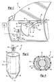
- Fig. 1 illustrates a front view of a vehicle door 10 utilizing an "arm and sector" window regulator 12.
- the window regulator 12 is powered by a motor 16 housed within a motor housing 18.
- the window regulator 12 is controlled by a window controller 20, which allows a window 14 to move upwardly and downwardly.
- the window regulator 12 includes a pair of pivotally attached arms 22, 24 and a sector 26.
- the sector 26 is substantially curved and includes a plurality of teeth 44.
- the size of the several components are not to scale and are only shown to exhibit one type of window drive mechanism.
- the pair of arms 22, 24 are connected at a pivot point 28 and include a first arm 22 and a second arm 24.
- Each arm 22, 24 has a first end, 30, 32, respectively, which is slidingly engaged to a first rail 34.
- the lower edge 36 of the window 14 is attached to the first rail 34, the window 14 moving upwardly and downwardly with the first rail 34.
- the first arm 22 further includes a second end 38 connected to the sector 26.
- the second arm 24 further includes a second end 40 which slidingly engages the second rail 42, the second rail 42 being substantially parallel to the first rail 34.
- the second rail 42 is stationary and attached to the vehicle door 10.
- the motor rotor 16 rotates within the motor housing 18, driving the window 14 upwardly and downwardly.
- the motor rotor 16 includes a bearing end 46 and an oppositely positioned gear end 48.
- the bearing end 46 is inserted within a bearing 50 on the top portion 58 of motor housing 18.
- the gear end 48 rotates and threads 52 on the gear end 48 engage a gear 54. As known, this moves the window.
- FIGS 3 and 4 illustrate a first embodiment of the motor housing 18 of the present invention.
- the motor housing 18 is formed of a composite material by injection molding.
- the hollow motor housing 18 is shaped to receive a motor 16 and includes a substantially cylindrical body portion 56 and a tapered top portion 58.
- a substantially cylindrical ferrous magnet housing 60 lines the interior surface 62 of the body portion 56 of the composite motor housing 18.
- the composite motor housing 18 is molded over the ferrous magnet housing 60.
- the two oppositely positioned magnet stators 64 are inserted within the motor housing 18.
- the magnet stators 64 generate magnetic field and assist the inserted motor rotor 16 to drive the window 14.
- the magnets 64 have a curvature substantially equal to the curvature of the motor rotor 16. As the motor 16 drives, the window 14 is operatively raised and lowered.
- the ferrous magnet housing 60 controls the magnetic field produced by the magnets 64 by preventing the magnetic field from escaping from the motor housing 18 and disrupting other components in the vehicle door 10.
- the motor housing 18 is formed of a ferrous metal matrix composite material.
- the ferrous magnet housing 60 can be eliminated.
- the ferrous matrix mixed within the composite material prevents the magnetic field of a magnet stators 64 from escaping from the motor housing 18.
- a sufficient amount of ferrous material is mixed within the composite material to sufficiently prevent the magnetic field from escaping.
- a bearing 50 is molded in the top portion 58 of the motor housing 18.
- the bearing end 46 of the motor rotor 16 is inserted into an aperture 68 located substantially in the center of the bearing 50.
- the bearing 50 can also be integrated into the top portion 58 of the motor housing 18, eliminating the need for a molded in bearing 50.
Landscapes
- Engineering & Computer Science (AREA)
- Power Engineering (AREA)
- Physics & Mathematics (AREA)
- Electromagnetism (AREA)
- Window Of Vehicle (AREA)
- Motor Or Generator Frames (AREA)
- Power-Operated Mechanisms For Wings (AREA)
- Iron Core Of Rotating Electric Machines (AREA)
Abstract
Description
Claims (10)
- An housing (18) for a motor (16) comprising:a relatively large hollow body portion (56) formed of a composite material having an interior surface;a relatively small top portion (58); anda material (66) to prevent magnetic forces generated by an inserted magnetic material from escaping from said housing.
- A vehicle closure drive comprising:a closure (14);a regulator (12) to move said closure between an open position and a closed positiona motor (16) to drive said regulator; anda housing (18) to house said motor formed of a composite material including a hollow body (56) having an interior surface and a top portion (58), and a material (66) to prevent magnetic forces generated by a magnetic material from escaping from said housing.
- The vehicle closure drive or housing as recited in any preceding claim wherein said body portion and said top portion of said housing are both substantially cylindrical in shape.
- The vehicle closure drive or housing as recited in any preceding claim wherein said material covers said interior surface of said hollow body portion.
- The vehicle closure drive or housing as recited in any one of claims 1 to 3 wherein said material is mixed within said composite material.
- The vehicle closure drive or housing as recited in claim 4 or claim 5 wherein said material is ferrous.
- The vehicle closure drive or housing as recited in any preceding claim wherein said housing further includes a bearing positioned in said top portion of said housing.
- The vehicle closure drive or housing as recited in claim 7 wherein said bearing is molded in said top portion of said motor housing.
- The vehicle closure drive or housing as recited in claim 7 wherein said bearing is integrated in said top portion of said motor housing.
- The vehicle closure drive or housing as recited in any preceding claim wherein said magnetic material is a magnet positioned within said body portion of said housing.
Applications Claiming Priority (2)
| Application Number | Priority Date | Filing Date | Title |
|---|---|---|---|
| US09/740,228 US20020073621A1 (en) | 2000-12-18 | 2000-12-18 | Over molded motor housing |
| US740228P | 2000-12-18 |
Publications (2)
| Publication Number | Publication Date |
|---|---|
| EP1215802A2 true EP1215802A2 (en) | 2002-06-19 |
| EP1215802A3 EP1215802A3 (en) | 2004-03-17 |
Family
ID=24975582
Family Applications (1)
| Application Number | Title | Priority Date | Filing Date |
|---|---|---|---|
| EP01309392A Withdrawn EP1215802A3 (en) | 2000-12-18 | 2001-11-06 | Composite material motor housing |
Country Status (4)
| Country | Link |
|---|---|
| US (1) | US20020073621A1 (en) |
| EP (1) | EP1215802A3 (en) |
| JP (1) | JP2002247795A (en) |
| BR (1) | BR0105743A (en) |
Cited By (1)
| Publication number | Priority date | Publication date | Assignee | Title |
|---|---|---|---|---|
| DE102006002628A1 (en) * | 2006-01-19 | 2007-08-02 | Zf Friedrichshafen Ag | Housing for gearing, plant or vehicle has its own material and further material integrated as at least one form element into housing for noise reduction or transmission of force and/or torque |
Families Citing this family (4)
| Publication number | Priority date | Publication date | Assignee | Title |
|---|---|---|---|---|
| DE102013110466A1 (en) | 2013-09-23 | 2015-03-26 | Dr. Ing. H.C. F. Porsche Aktiengesellschaft | Electric machine for use in the automotive sector |
| DE102014217434A1 (en) * | 2014-09-01 | 2016-03-03 | Volkswagen Aktiengesellschaft | Electric machine and vehicle with such an electric machine |
| US11387723B2 (en) * | 2019-10-31 | 2022-07-12 | Deere & Company | Hot drop fastening of coated machine components |
| DE102021131945A1 (en) * | 2021-12-03 | 2023-06-07 | Brose Fahrzeugteile Se & Co. Kommanditgesellschaft, Bamberg | Drive unit for motorized adjustment of a closure element of a motor vehicle |
Family Cites Families (9)
| Publication number | Priority date | Publication date | Assignee | Title |
|---|---|---|---|---|
| US2324145A (en) * | 1940-12-24 | 1943-07-13 | Detroit Harvester Co | Regulator mechanism for vehicle windows or the like |
| JPS59135087U (en) * | 1983-02-26 | 1984-09-10 | シナノケンシ株式会社 | Permanent magnet step motor |
| JPS62181639A (en) * | 1986-02-04 | 1987-08-10 | Kanebo Ltd | Stepping motor with resin bracket |
| JPH0744818B2 (en) * | 1986-05-19 | 1995-05-15 | 三菱マテリアル株式会社 | Stepping motor |
| US4857812A (en) * | 1986-07-07 | 1989-08-15 | Mitsuba Electric Mfg. Co., Ltd. | Electric motor system for automobiles |
| JPH01286749A (en) * | 1988-05-10 | 1989-11-17 | Kanebo Ltd | Stepping motor with resin bracket |
| US5268607A (en) * | 1992-09-09 | 1993-12-07 | Webster Plastics | Molded resin motor housing |
| DE4439799C1 (en) * | 1994-11-08 | 1996-05-02 | Wolf Gmbh Richard | Electric drive unit for surgical tool |
| DE19524953A1 (en) * | 1995-07-08 | 1997-01-09 | Teves Gmbh Alfred | Electric motor esp. for driving pump of vehicle braking system - has stator with axial extension for fastening electric motor to unit housing |
-
2000
- 2000-12-18 US US09/740,228 patent/US20020073621A1/en not_active Abandoned
-
2001
- 2001-11-06 EP EP01309392A patent/EP1215802A3/en not_active Withdrawn
- 2001-11-29 BR BR0105743-0A patent/BR0105743A/en not_active Application Discontinuation
- 2001-12-10 JP JP2001375850A patent/JP2002247795A/en active Pending
Cited By (1)
| Publication number | Priority date | Publication date | Assignee | Title |
|---|---|---|---|---|
| DE102006002628A1 (en) * | 2006-01-19 | 2007-08-02 | Zf Friedrichshafen Ag | Housing for gearing, plant or vehicle has its own material and further material integrated as at least one form element into housing for noise reduction or transmission of force and/or torque |
Also Published As
| Publication number | Publication date |
|---|---|
| BR0105743A (en) | 2002-09-17 |
| US20020073621A1 (en) | 2002-06-20 |
| JP2002247795A (en) | 2002-08-30 |
| EP1215802A3 (en) | 2004-03-17 |
Similar Documents
| Publication | Publication Date | Title |
|---|---|---|
| US6550839B2 (en) | Vehicle pivoting closure power operating assembly | |
| US6055776A (en) | Power liftgate arm assist assembly | |
| US6202350B1 (en) | Power liftgate device | |
| EP0979746A3 (en) | Tailgate assembly | |
| EP0985581A3 (en) | Coat hook for vehicles | |
| DE10350452A1 (en) | Electronically controlled throttle device | |
| DE102006040232A1 (en) | Door drive for an automatic door | |
| US20020073621A1 (en) | Over molded motor housing | |
| EP0768442A3 (en) | Continuous motor vehicle door check operated by auxiliary force | |
| FR2740571A1 (en) | METHOD FOR CONTROLLING THE MOVEMENT OF A WORKPIECE | |
| US6283534B1 (en) | Active door upper | |
| EP1576251B1 (en) | Drive mechanism for swiveling a vehicle door or vehicle hood | |
| US20020020115A1 (en) | Device for opening and closing a vehicle slide door window | |
| CN211918344U (en) | Automobile built-in skylight mechanical group | |
| US8172299B2 (en) | Compartment door with force and effort control | |
| DE19838660A1 (en) | Drive device | |
| EP1227208A3 (en) | Cover for flexible signal connection for a transit vehicle door | |
| EP1149969A3 (en) | Vehicle aperture closure drive system | |
| DE3723679A1 (en) | VEHICLE DOOR, ESPECIALLY FRAMELESS VEHICLE DOOR FOR PERSONAL VEHICLES | |
| EP1276950B1 (en) | Coreless motor door closure system | |
| US20080313966A1 (en) | Door Module for a Vehicle Door | |
| US20010023556A1 (en) | Actuating drive for a motor vehicle | |
| JP2003525161A (en) | Vehicle wind load compensating tilted roof system and method of operation | |
| GB2315517B (en) | Pivot means for a removeable vehicle window | |
| JPH06135247A (en) | Vehicle fuel filler structure |
Legal Events
| Date | Code | Title | Description |
|---|---|---|---|
| PUAI | Public reference made under article 153(3) epc to a published international application that has entered the european phase |
Free format text: ORIGINAL CODE: 0009012 |
|
| AK | Designated contracting states |
Kind code of ref document: A2 Designated state(s): AT BE CH CY DE DK ES FI FR GB GR IE IT LI LU MC NL PT SE TR |
|
| AX | Request for extension of the european patent |
Free format text: AL;LT;LV;MK;RO;SI |
|
| RAP1 | Party data changed (applicant data changed or rights of an application transferred) |
Owner name: ARVINMERITOR TECHNOLOGY, LLC |
|
| PUAL | Search report despatched |
Free format text: ORIGINAL CODE: 0009013 |
|
| AK | Designated contracting states |
Kind code of ref document: A3 Designated state(s): AT BE CH CY DE DK ES FI FR GB GR IE IT LI LU MC NL PT SE TR |
|
| AX | Request for extension of the european patent |
Extension state: AL LT LV MK RO SI |
|
| RIC1 | Information provided on ipc code assigned before grant |
Ipc: 7H 02K 5/02 A |
|
| AKX | Designation fees paid | ||
| REG | Reference to a national code |
Ref country code: DE Ref legal event code: 8566 |
|
| STAA | Information on the status of an ep patent application or granted ep patent |
Free format text: STATUS: THE APPLICATION IS DEEMED TO BE WITHDRAWN |
|
| 18D | Application deemed to be withdrawn |
Effective date: 20040920 |