The present invention concerns a duplex relay or
system reliability module to be used as a component in
high integrity, control system applications, such as
electrical, low-voltage, switchboards to improve the
reliability of switchboard operation.
Most control systems fail due to damage or faults
in the interconnecting wiring between the initiating
contacts in one device and the receiving devices, e.g.
relay coils, closing releases, shunt trip coils, undervoltage
coils etc., giving rise to open circuits or
short circuits.
The aim of the present invention is to provide an
intermediate module, which provides redundancy and fault
tolerance of control signals, whilst still maintaining
the primary function of receiving initiating contacts
and providing an output contact to go forward to the
receiving device in the next phase of the process.
The module is connected between the input to the
system and the receiving device and is preferably
arranged as close as possible to the receiving device to
minimise the risk of failures between them.
Thus, in accordance with the present invention,
there is provided a system reliability module comprising
control signal input means; contacts responsive to input
control signals; output means providing signals in
response to the state of said contacts; a main power
supply and an internal back-up battery power supply;
characterised by means for monitoring said main power
supply and for automatically connecting said back-up
power supply when said main power supply falls below a
predetermined level; and means for monitoring said input
means, said contacts and said output means and for
indicating faults or failures.
Although the faults or failures are communicated in
any known way, the preferred means is a plurality of
LEDs located on the front of said module, arranged to
indicate the nature of the fault and/or failure
detected.
Preferably, LEDs also indicate the state of the
main power supply and/or the internal battery.
There is preferably an indicator (LED) for each of
a number of alarm functions, with each alarm function
being separately connected to the various parts of the
system.
The module preferably operates in a standard non-latching
mode and a latching mode. Selection of
operating mode is by connections.
The module preferably provides some redundancy in
the contacts, by means of relays adapted to be energised
to prevent false operation if associated contacts are
welded. The preferred module contains monitoring
circuits for the auxiliary DC supply, an internal
rechargeable battery backed power supply and volt-free
relay output alarm contacts for every function, which
can be monitored by a BMS or an overall supervisory
system.
In summary, in the preferred embodiment, the
'initiating' contacts connect to local 'Loop Limit'
circuits, which encode the contact operation into 5mA
for 'open' and 16mA for 'closed'. These current loops
provide signal integrity over long distances (in excess
of 100 metres) to the monitoring SRM200 System
Reliability Module whose output contacts connect to the
next stage of the control system. By monitoring the
Loop currents the SRM200 can distinguish between valid
open and closed contacts and short-circuit or open-circuit
Loop Fault conditions.
Preferably, four 'Loop Limit' circuits are included
and electronically isolated from the rest of the module.
Thus, the 'Loop Limit circuits' inside one module can be
used for the sensing circuitry of a different module.
Preferred embodiments of this invention will now be
described, by way of example only and with reference to
the accompanying drawings.
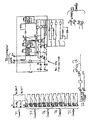
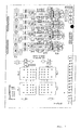
Referring to Fig. 1, the system comprises a front
panel (1) and a rear panel (2) housed in a DIN standard
case. The case is through panel mounted and secured
using quick release panel mounting clips. The rear
panel (2) is preferably
a glass fibre panel with silk screen terminal
identification.
Such system reliability modules are typically used
within switch boards to verify correct operation and to
provide a volt-free contact for the next stage of a
control system. A typical mains failure stand-by system
might employ five of these units.
Ten LEDs (3) on the front panel indicate
operational status and an on-board lamp test button (4),
preferably a touch sensitive button, is also provided to
check the functioning of the LEDs.
Certain of the alarm functions (indicated by the
LEDs) have three separate volt-free contact sets which
allow connections to the various system components,
namely the building management system (BMS), the alarm
system (annunciator) and the process controller (PLC).
The auxiliary DC voltage is continually monitored.
If the external supply fails, this is indicated by an
LED and an internal battery provides back-up power. The
internal batteries (preferably two PP3 rechargeable NIMH
or NICAD batteries) are automatically recharged from the
auxiliary DC supply. If required, these internal back-up
batteries can be inspected or replaced during routine
maintenance via access draw (5) in the rear of the
module. Removing either battery, with a healthy
auxiliary DC supply, does not affect operation of the
module.
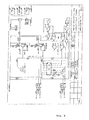
Referring to the circuit diagram of Fig. 4, once
connected to the control panel and a valid DC supply
voltage is applied, the internal batteries are 'charged'
by the auxiliary DC supply. If the auxiliary DC supply
falls, the internal batteries will automatically power
the unit.
The internal battery is switched out of the circuit
if either the battery voltage falls below a
predetermined charge threshold e.g. 0.9V per cell (where
1.0V per cell is fully discharged), or if the unit is
removed from the panel, indicated in Fig. 4 by 7 and 8
of connector J1 being open circuit.
The module operates automatically and can operate
in either non-latching (standard) mode or latching
(latch) mode operation. The operating mode is
determined via connector J5 terminal 46,47 and the
connections to J2 terminals 17, 18, 19, 20, 21, 22, 23
and 24.
In the standard or non-latching mode, four
connections (two auxiliary, two-wire, volt-free normally
open 'field contacts') are required from the 'switch
function' being monitored. The two-wire volt-free
normally open 'Relay Module Output' closes to verify
correct operation of this 'switch function'.
In the latched mode, the field contacts latch on
momentary operation and therefore require four further
contacts (two auxiliary, two-wire, volt-free, normally
closed 'de-latch field contacts') from the 'switch
function' being monitored.
Various fault conditions can be indicated by
respective LEDs on the front panel. In particular, the
LEDs indicate when the auxiliary DC voltage is out of
limits; the auxiliary DC voltage is lost; on-board
battery is out of limits; or there is an input fault.
For any of these conditions, separate volt-free
relay contacts are provided for the different system
parts, i.e. the building management system (BMS), the
alarm system and the process controller (PLC).
In the preferred embodiment, the front panel LEDs
indicate the following status information:
The different status indicator combinations may be
as follows:
With all parameters correct and both Input 1 and 2
received for:
- Auxiliary DC Voltage in Limits
- On Board Battery in Limits
- Input 1 Received
- Input 2 Received
- Output Available
If Input-1 is received without Input-2 for five
seconds:
- Input 1 Received
- Input Fault
If Input-2 is received without Input-1 for five
seconds:
- Input 2 Received
- Input Fault
- Output Available
If Input-1 is received but Input-2 Loop is 'out of
limits' for five seconds:
- Input 1 Received
- Input Fault
- Loop Fault
- Output Available
If Input-2 is received but Input-1 Loop is 'out of
limits' for five seconds:
- Input 2 Received
- Input Fault
- Loop Fault
- Output Available
If at least one Current Loop per channel is 'out of
limits' for one second (Double Loop Fault):
The following rear panel indicators may also be
provided:
- F1
- Field Contact-1 current Loop 'valid'
- D1
- De-Latch Contact-1 current Loop 'valid'
- D2
- De-Latch Contact-2 current Loop 'valid'
- F2
- Field Contact-2 current Loop 'valid'
These rear panel indicators assist in fault finding
as they indicate correct operation of the Current Loops
that are sensed by this module.
In Normal mode (mode link made) Loop-3 and Loop-4
de-latch circuits will not be required and their
respective status LED's D1 and D2, on the rear of the
unit, will not be lit.
For any of the following conditions:
- Auxiliary DC Voltage out of Limits
- Loss of Auxiliary DC Voltage
- On Board Battery Voltage out of Limits
- Input Fault (including Loop Faults)
Separate volt-free relay contacts are provided for:
- Building Management System (BMS)
- Central Alarm System
- Process Controller (PLC)
Preferably, the module should be calibrated in the
factory and no user access should be provided. It is
envisaged that various different versions may be made
available, having different supply voltages. For
example, it is expected that modules would be available
in a 30V DC auxiliary supply version and a 24V DC supply
version. The thresholds determining when a low or high
auxiliary DC voltage condition exists will depend on the
voltage supply for the particular version.
Similarly, the threshold for determining that the
internal battery is not being charged may be set
according to the supply voltage or may be common to all
versions, the same applies for the on-board battery in
limits and the on-board battery drop-out thresholds.
The following tables give preferred specifications
for parts of the system.
| AUXILIARY DC SUPPLY |
| | Level | Tolerance | Comments |
| Nominal Aux.DC Supply | 24V | | External 12cell sealed L.A Battery |
| Absolute Max. Aux. DC | 36V | | Transient Protected |
| Minimum Aux. DC | 18V |
| Aux. DC Volts in Limits | < 33.0V | +/- 0.1V |
| | > 22.0V | +/- 0.1V |
| Low Aux. DC Volts | < 22.0V | +/- 0.1V | 0.1 - 10s delay, Set to mid-scale |
| Loss of Aux. Dc Voltage | ≤16.0V | Approx. | (dependant on dc-dc converter) |
| | > + 0.5V | Approx. | Recovery from Loss of Aux. Dc |
| Quiescent Current | 470mA | | Nominal 24Vdc supply (see note 1) |
| Maximum Current | 800mA | | Minimum 16Vdc supply (see note 2) |
| INTERNAL BATTERY |
| | Level | Tolerance | Comments |
| High Volts | ≥10.5 | 1.5 V/cell |
| In Limits | 10.5 < > 7.0 |
| Low Volts | ≤7.0 | 1.0 V/cell | 0.1 - 10s delay, Set to mid-scale |
| Drop-out | < 6.3 | 0.9 V/cell | to protect the internal batteries |
| Number of Batteries | 2 | Connected in parallel |
| Type | NIMH PP3 | NICAD can be used |
| Capacity | 300 mAhr | 150mAhr each |
| Trickle Charge Rate | 6 mA | Approx. 3mA each (C / 50) |
| Back-up duration | 10 min | Approx. duration from fully charged state |
| Life expectancy |
| | 5 years | Under optimum conditions |
| INPUT SENSING |
| Condition | Value | Comments |
| Input valid - Open Contact | 5.0 +/ - 1.0 mA | Current out of limits = Loop fault |
| Input valid - Closed Contact | 16.0 +/ - 2.0 mA | Current out of limits = Loop fault |
| Input Response | ≥40 mSec | Latch / De-Latch Time |
| Input Fault delay | 5 sec approx. |
| Loop Fault - Loop open-circuit | 13V approx. | Open-circuit Loop voltage |
| Loop Fault - Loop short-circuit | 22 mA approx. | Maximum current per Loop |
| Loop Fault Delay | 1 sec approx. |
| RELAY CONTACTS |
| | Rating | Comments |
| Relay Module Output N/C | 5A 230VAC | Term. 26 & 27 Resistive Load |
| Relay Module Output N/O | 5A 230VAC | Term. 14 & 15 Resistive Load |
| Input Fault | 1A 30VDC | Term. 28 & 33 Resistive Load |
| Aux. DC Volts out of Limits | 1A 30VDC | Term. 34 & 39 Resistive Load |
| Loss of Aux. DC volts | 1A 30VDC | Term. 40 & 45 Resistive Load |
| On-Board Batt. out of Limits | 1A 30VDC | Term. 1 to 6 Resistive Load |
For Inductive Loads, the currents above MUST be derated
to 14% (x 0.14).
| ENVIRONMENT |
| | | Comments |
| Storage Temperature | - 25 to + 70 deg.C |
| Operating Temperature | -10 to + 40 deg.C |
| Note |
| 1. Correct operation, 'Normal (non-latching) mode', both field contacts closed. |
| Note 2. Fault condition, 'Latching mode', all (4) Loop circuits individually shorted. |
The following tables give some indication of the
likely parameters for different versions of the module.
| 24VDC AUX. SUPPLY VERSION |
| | Threshold | Delay | Comments |
| Aux. DC Volts in Limits | > 23.5 V | no delay | RL4 energised |
| < 32.0 V |
| Aux. DC Voltage out of limits | > 32.0 V | no delay | RL4 de-energised |
| < 23.5 V | 0.1 - 10s |
| Quiescent Current | | At 24V DC | All conditions normal |
| Maximum Current | | At 24V DC | Worst case conditions + Lamp Test |
| AUX DC | RL5 de-energised |
| Operating Range: 18 -33 V |
| Operating Limits: 9 - 36V |
| Loss of AUX DC: <8V |
| COMMON FEATURES |
| | | | Comments |
| On-board battery | 2xPP3 | in Parallel | 7 cells/240mAH |
| On-board battery float charging | 9.8V | @2.4mA | 1.4V/cell |
| | Threshold | Delay | Comments |
| On-Board Battery in Limits | > 1.7V | no delay | RL6 energised |
| > 11.2V |
| On-Board Battery out of limits | > 11.2V | delay | RL6 de-energised |
| < 7.7V | 0.1 - 10s |
| On-Board Battery drop-out | < 6.3V | no delay | 0.9V / cell RLB de-energised |
The module preferably has two internal batteries of
the PP3 NIMH type but NICAD batteries could also be
used. The batteries preferably have a capacity of
150mAH with a trickle charge rate of 6mA and an
approximate back-up duration of 10 minutes from a fully
charged condition. The life expectancy of such
batteries is around five years (under optimum
conditions).
The use of NIMH batteries minimises the 'memory
effect'. The batteries are easily replaceable without
needing to open the module and can be replaced with the
module in service, provided a healthy DC auxiliary
supply is present.
The voltage of the internal batteries (typically
1.4V per cell) is monitored and indicated by means of an
LED on the front panel and connected with an alarm
output.
The batteries preferably have an automatic drop-out
(typically at 0.9V per cell) to protect the batteries.
The batteries are disabled when the module is removed
from the control panel, i.e. when connector J1 in Fig. 4
is removed.
The module itself is preferably constructed to
allow through-panel mounting and to be built into a DIN
standard case. The connectors are preferably two-piece
screw clamp industry standard connectors. The
electronics are incorporated in a quadruple PCB assembly
which plugs together to simplify production. The PCBs
themselves will be described in more detail below.
The module is suitable for latching and non-latching
modes of operation.
The main power supply is preferably of a switch
mode (SMPS) design for maximum efficiency and minimal
heat dissipation and the internal battery supports the
SMPS if the DC supply fails.
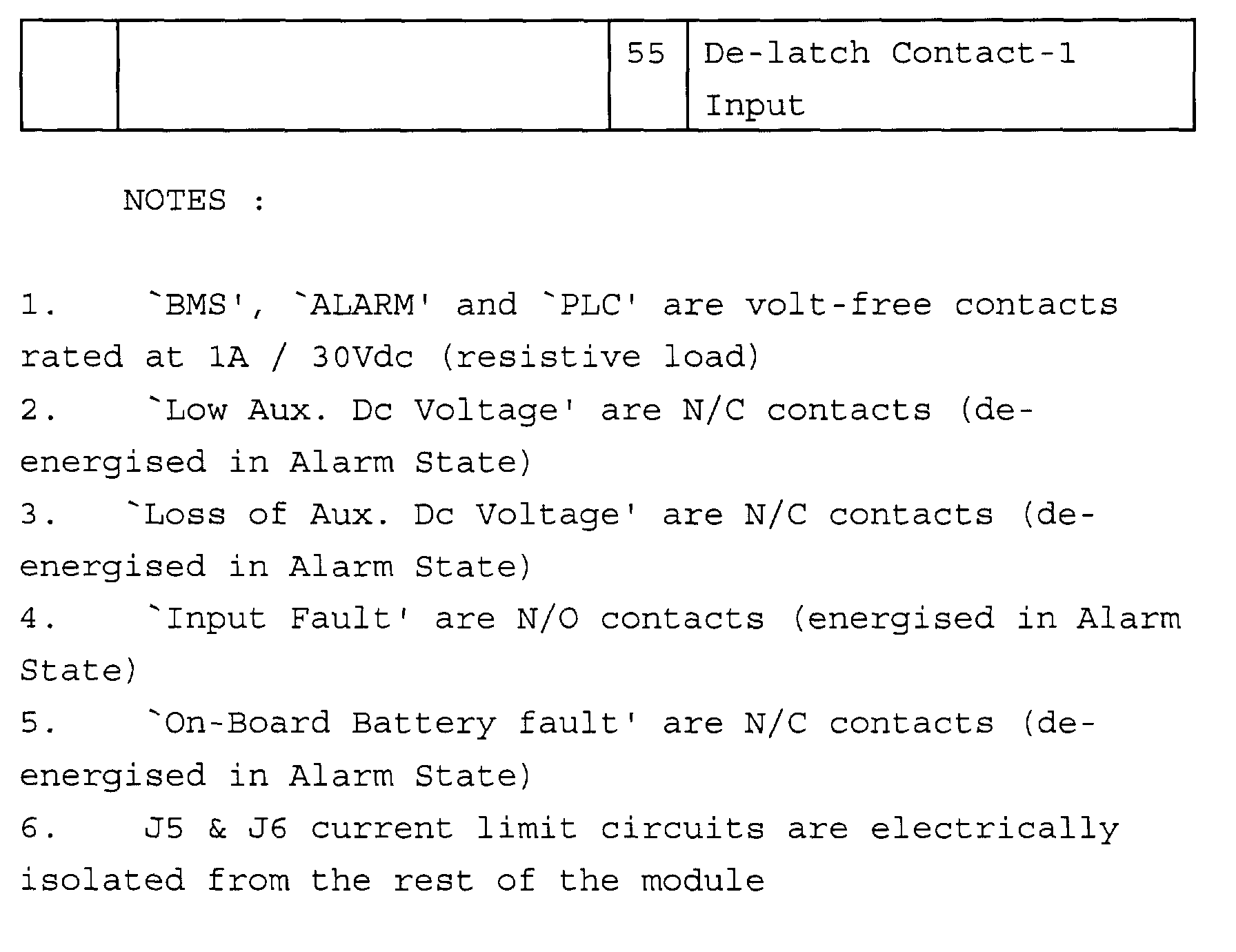
The various terminal connections are summarised in
the following table:
As mentioned above, the module preferably has a
quadruple PCB construction. Ten sections of circuitry
are divided between the four PCBs.
The first PCB is the 'display PCB'. This PCB is
located directly behind the front panel and carries the
LEDs, the driver circuits, the lamp test circuitry and
push-switch and the inter-board connections.
The second PCB is the 'power PCB' which carries
three sections of circuitry:
The third PCB is the "sensing PCB" which carries
three sections of circuitry:
The fourth PCB is the 'monitoring PCB' which also
carries three sections of circuitry:
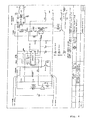
Fig. 3 shows a circuit diagram of the display PCB.
A transistor driver is used to switch the LEDs from
logic signals. A feature of this IC is the internal
pull-down diodes connected to each output with their
common cathodes connected to pin 9. Thus, momentarily
connecting pin 9 to the common negative terminal will
test all of the relevant LEDs.
Momentary activation of the lamp test button (4),
which is mounted behind the front label, connects the
+12V power line through the blocking diode and current
limiting resistor into two drivers. These are connected
in parallel to sink sufficient current for the ten LEDs.
Seven of the LEDs are switched directly via open
collector transistors in other circuit, and, therefore
steering diodes are included to complete the lamp test
feature.
The other three PCBs plug in via single in-line
(SIL) headers.
This modular construction has the advantages of
allowing quick assembly, reduced labour costs, and fault
finding in that individual PCBs can be inspected, recalibrated
or replaced as required. The costs of
updates and re-designs are also minimised.
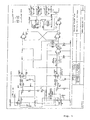
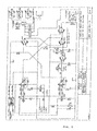
Fig. 4 is a schematic circuit diagram of the power
supply PCB. Fig. 5 is a schematic circuit diagram of
the power PCB battery in limits circuitry. Fig. 6a is a
schematic circuit diagram of the power PCB field contact
circuitry for normal operation, while Fig. 6b is for
latching operation.
The module is powered from an Auxiliary Dc Supply
(term. 11 & 12 J1) via a 15W DC-DC converter to provide
a constant 15Vdc over a wide supply range (i.e. 16V to
36Vdc).
The 15Vdc is wire or'ed via steering diodes with
the internal 8.4V rechargeable battery to feed a purpose
designed 'step-up' switch mode power supply (SMPS),
designed around the proven LM78S40. This device has an
accessible 1.2V Band-gap reference and universal op-amp.
The battery relay RLB switches the batteries into
circuit (provided that terminals 7 and 8 of connector J1
are connected) whenever the supply is connected for the
first time, i.e. if the module is re-fitted into the
control panel.
While the DC-DC converter outputs I5V, the step-up
SMPS is not running and approximately 13Vdc powers the
module. However, if the 15Vdc collapses, the on-board
battery via the step-up SMPS will maintain 11.5V at the
output.
The on-board battery voltage is buffered and fed
back to minimise battery drain by the monitoring
circuitry. An op-amp is used to compare the battery
voltage, via a potential divider, with a 1.2V reference.
If, during a supply failure, the battery voltage falls
below 6.3V (7 cells at 0.9V per cell), the battery relay
(RLB) will de-energise, switching the battery out of
circuit and powering down the module in a 'guillotine'
action.
A 'Transorb' device provides transient protection
of the auxiliary DC supply. A Common-Mode suppression
choke minimises noise from being reflected back into the
DC supply.
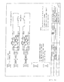
Referring to Figure 5, on initial power-up the
latch is reset and relay RL6 de-energised, indicating
that the internal battery voltage is out of limits.
If the battery voltage rises above the LOW
threshold, e.g. 7.0V (1.0V per cell) and below the HIGH
threshold, e.g. 10.5V (1.5V per cell) the latch is set
and RL6 energises, indicating that the battery is within
limits.
If the battery voltage is above the HIGH threshold
or falls below the LOW threshold for a DELAY time (0.1
to 10 seconds), the latch is reset and RL6 de-energised,
to indicate the "out of limits" fault condition.
Front panel status LEDs are switched via a spare
contact set on RL6 and thus confirm that the relay is
functioning correctly.
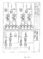
Referring now to Fig. 6a, in the standard non-latching
mode, closing field contact 1, i. e. terminals
50 and 51 of connector J5 energises relay RLX which, in
turn, energises relay RL1. This redundancy prevents
false operation if the RL1/1 contacts are fused or
welded.
Closing field contact 2 (terminals 54 and 55 of J6)
energises relay RLY which, in turn, energises relay RL2.
This redundancy prevents false operation if RL2/4
contacts are welded.
Referring now to Fig. 6b, in the latching mode,
closing field contact 1 (terminals 50 and 51 of J5)
operates as in the standard mode described above, except
that only momentary operation is required since relays
RLX and RL1 are latched via the decoding logic. They
are unlatched by momentary operation of the de-latching
field contact (terminals 58 and 59 of J6).
Similarly, field contact 2 operates as in the
standard mode except only momentary operation is
required since relays RLY and RL2 are latched via the
decoding logic. They are, again, unlatched by the de-latching
field contact (terminals 62 and 63 of J6).
Timer T1 input is energised if relay RL1 is energised
without RL2. Timer T1 input is energised if relay RL2
is energised without RL1.
Relay module output (terminals 14 and 15 of J2)
closes if either RL1 and RLX or RL2 and RLY operate.
Relay module output (terminals 26 and 27 of J2) open if
RLX or RLY or RL2 operate.
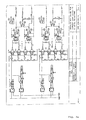
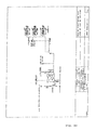
Fig. 7 shows a circuit diagram of the sensing PCB.
Fig. 7a shows the channel-1 current loop circuitry of
the sensing PCB. Fig. 7b shows the channel-2 current
loop circuitry of the sensing PCB. Fig. 7c shows the
decoding logic circuitry of the sensing PCB. Fig. 7d
shows the power relays of the sensing PCB.
Fig. 8 shows a schematic circuit diagram of the
circuit fault timer circuitry of the monitoring PCB.
Fig. 9 shows a schematic circuit diagram of the
auxiliary DC voltage in limits circuitry of the
monitoring PCB and Fig. 10 shows a schematic circuit
diagram of the loss of auxiliary DC voltage circuitry of
the monitoring PCB.
Relay RL3 energises to indicate a 'circuit failure'
if either:
However, RL3 is non-latching and will de-energise
if there is no longer a fault condition.
The on-board LEDs provide indications to aid
testing during manufacture.
On initial power-up the latch is reset, de-energising
relay RL4, indicating that the auxiliary DC
supply voltage is out of limits. If the auxiliary DC
voltage rises above the LOW threshold, e. g. 22V and
below the HIGH threshold, e. g. 33V, the latch is set
and RL4 energises to indicate that the auxiliary DC
voltage is within limits.
If the auxiliary voltage rises above the HIGH
threshold (no delay) or falls below the LOW threshold
for a DELAY time (0.1 to 10 seconds) the latch is reset
and RL4 de-energises, to indicate the "out of limits"
fault condition.
Front Panel status LEDs are switched via the spare
contact set on RL4 and thus confirm that thte relay is
functioning correctly.
As this circuitry is directly sensing the Auxiliary
DC Supply, a 1W DC-DC converter is employed to isolate
the supply rails. Likewise, an opto-isolator is
required to connect the logic output to the relay driver
circuitry.
If "Loss of Auxiliary DC Supply" is sensed, QQ is
pulled low to reset the latch (bypassing the Delay) and
de-energising RL4 to indicate an "out of limits" fault
condition.
A feature of the 15W DC-DC Converter is that the
15V output collapses, if the Auxiliary DC Supply voltage
falls below a nominal threshold. Thus, RL5 is connected
directly to the 15V output, de-energising to indicate
'Loss of Auxiliary DC Supply'.
The Front Panel status LED is switched via the
spare contact set on RL5 as is the opto-isolator to
drive QQ via the 2N7000. This ensures that the
Auxiliary DC Supply is also indicating 'out of limits'.
The opto-isolator is required because the
'Auxiliary DC Supply monitoring circuitry' is
electrically isolated from the other circuitry.
On initial power-up with the auxiliary DC supply
18V, the DC-DC convertor (Fig. 4) outputs 15V,
energising relay RL5 to indicate that the supply voltage
is not lost. If the auxiliary DC supply falls below
approx 16V, the 15V collapses and RL5 de-energises to
indicate loss of Auxiliary DC supply.
Further J1 terminals (9 and 10) together with
terminal 8 are used to externally check 'internal-battery'
voltage and/or internal-battery charge current.
Briefly, the system is operated as follows:
Once connected to the control panel and a valid
auxiliary DC supply voltage is applied, the internal
battery is switched into circuit and continually
'Trickle' charged. Whenever the supply is interrupted
(or falls sufficiently low) the internal batteries will
power the unit.
However, the internal battery can only be switched
out of circuit if
The SRM200 operates automatically and requires no
user adjustment with the operating mode selected by
connection.
Standard Mode (non-latching):
Mode Link fitted and de-latch circuits not required.
Contact closure (16mA) sensed in either (Field Contact)
current loop will energise the module output. Contact
open must be sensed (5mA) in both (Field Contact)
current-loops to de-energise the module output.
Latched Mode:
Mode link omitted and de-latch circuits required.
Momentary contact closure sensed (16mA pulse > 40mSec)
in either (Field Contact) Current Loop to latch the
relevant input circuit and energise the module output.
Momentary contact opening sensed (5mA >40mSec) in either
(de-latched contacts) current loops will unlatch the
relevant input circuit. Both circuits must unlatch in
order to de-energise the module output.
If a 'Loop Fault' condition occurs on either
current loop of one channel, the module output will be
driven from the remaining working channel. In the event
of a 'double loop fault' where at least one current loop
per channel is 'out of limits' the module output will
de-energise. However, if the 'Loop Fault' condition is
removed, the module output will not change state.
A 'Loop Fault' condition means that the respective
Loop Current is 'out of limits'.
In a modified version, the module operates in the
same way as described above, except that it cannot power
the current loops, only monitor those of another module.
The table below shows the preferred specification
for such a module.
| AUXILIARY DC SUPPLY |
| | Level | Tolerance | Comments |
| Nominal Aux.DC Supply | 24V | | External 12cell sealed L.A Battery |
| Absolute Max. Aux. DC | 36V | | Transient Protected |
| Minimum Aux. DC | 18V |
| Aux. DC Volts in Limits | < 33.0V | +/- 0.1V |
| | > 22.0V | +/- 0.1V |
| Low Aux. DC Volts | < 22.0V | +/- 0.1V | 0.1 - 10s delay, Set to mid-scale |
| Loss of Aux. Dc Voltage | ≤16.0 | Approx. | (dependant on dc-dc converter) |
| | > +0.5V | Approx. | Recovery from Loss of Aux. Dc |
| Quiescent Current | ≤470mA | | Nominal 24Vdc supply (see note 1) |
| Maximum Current | ≤600mA | | Approx.16Vdc supply (see note 1) |
| INTERNAL BATTERY |
| | Level | Tolerance | Comments |
| High Volts | ≥10.5 | 1.5 V/cell |
| In Limits | 10.5 < > 7.0 |
| Low Volts | ≤7.0 | 1.0 V/cell | 0.1 - 10s delay, Set to mid-scale |
| Drop-out | ≤6.3 | 0.9 V/cell | to protect the internal batteries |
| Number of Batteries | 2 | Connected in parallel |
| Type | NIMH PP3 | NICAD can be used |
| Capacity | 300 mAhr | 150mAhr each |
| Trickle Charge Rate | 6 mA | Approx. 3mA each (C / 50) |
| Back-up duration | 10 min | Approx. duration from fully charged state |
| Life expectancy |
| | 5 years | Under optimum conditions |
| INPUT SENSING |
| Condition | Value | Comments |
| Input valid - Open Contact | 5.0 +/ - 1.0 mA | Current out of limits = Loop fault |
| Input valid - Closed Contact | 16.0 +/ - 2.0 mA | Current out of limits = Loop fault |
| Input Response | ≥40 mSec | Latch / De-Latch Time |
| Input Fault delay | 5 sec approx. |
| Loop Fault - Loop open-circuit | 13V approx. | Open-circuit Loop voltage |
| Loop Fault - Loop short-circuit | 22 mA approx. | Maximum current per Loop |
| Loop Fault Delay | 1 sec approx. |
| RELAY CONTACTS |
| | | Comments |
| Relay Module Output N/C | 5A 230VAC | Term. 26 & 27 Resistive Load |
| Relay Module Output N/O | 5A 230VAC | Term. 14 & 15 Resistive Load |
| Input Fault | 1A 30VDC | Term. 28 & 33 Resistive Load |
| Aux. DC Volts out of Limits | 1A 30VDC | Term. 34 & 39 Resistive Load |
| Loss of Aux. DC volts | 1A 30VDC | Term. 40 & 45 Resistive Load |
| On-Board Batt. out of Limits | 1A 30VDC | Term. 1 to 6 Resistive Load |
For Inductive Loads, the currents above MUST be derated
to 14% (x 0.14).
| ENVIRONMENT |
| | | Comments |
| Storage Temperature | - 25 to + 70 deg.C |
| Operating Temperature | -10 to + 40 deg.C |
| Note |
| 1. Correct operation, 'Normal (non-latching) mode', both field contacts closed. |
The following tables show the preferred terminal
connections for such a module.