EP1215692A2 - Push-Push switch for switching heavy-current - Google Patents
Push-Push switch for switching heavy-current Download PDFInfo
- Publication number
- EP1215692A2 EP1215692A2 EP01129866A EP01129866A EP1215692A2 EP 1215692 A2 EP1215692 A2 EP 1215692A2 EP 01129866 A EP01129866 A EP 01129866A EP 01129866 A EP01129866 A EP 01129866A EP 1215692 A2 EP1215692 A2 EP 1215692A2
- Authority
- EP
- European Patent Office
- Prior art keywords
- contact
- moving contact
- operating shaft
- coil spring
- fixed
- Prior art date
- Legal status (The legal status is an assumption and is not a legal conclusion. Google has not performed a legal analysis and makes no representation as to the accuracy of the status listed.)
- Granted
Links
Images



Classifications
-
- H—ELECTRICITY
- H01—ELECTRIC ELEMENTS
- H01H—ELECTRIC SWITCHES; RELAYS; SELECTORS; EMERGENCY PROTECTIVE DEVICES
- H01H1/00—Contacts
- H01H1/12—Contacts characterised by the manner in which co-operating contacts engage
- H01H1/14—Contacts characterised by the manner in which co-operating contacts engage by abutting
- H01H1/20—Bridging contacts
- H01H1/2016—Bridging contacts in which the two contact pairs commutate at substantially different moments
-
- H—ELECTRICITY
- H01—ELECTRIC ELEMENTS
- H01H—ELECTRIC SWITCHES; RELAYS; SELECTORS; EMERGENCY PROTECTIVE DEVICES
- H01H13/00—Switches having rectilinearly-movable operating part or parts adapted for pushing or pulling in one direction only, e.g. push-button switch
- H01H13/02—Details
- H01H13/12—Movable parts; Contacts mounted thereon
-
- H—ELECTRICITY
- H01—ELECTRIC ELEMENTS
- H01H—ELECTRIC SWITCHES; RELAYS; SELECTORS; EMERGENCY PROTECTIVE DEVICES
- H01H13/00—Switches having rectilinearly-movable operating part or parts adapted for pushing or pulling in one direction only, e.g. push-button switch
- H01H13/50—Switches having rectilinearly-movable operating part or parts adapted for pushing or pulling in one direction only, e.g. push-button switch having a single operating member
- H01H13/56—Switches having rectilinearly-movable operating part or parts adapted for pushing or pulling in one direction only, e.g. push-button switch having a single operating member the contact returning to its original state upon the next application of operating force
- H01H13/562—Switches having rectilinearly-movable operating part or parts adapted for pushing or pulling in one direction only, e.g. push-button switch having a single operating member the contact returning to its original state upon the next application of operating force making use of a heart shaped cam
Definitions
- the present invention relates to a switch, particularly relates to a push-push switch for switching heavy-current.
- variable and fixed contacts of a conventional type switch particularly a push-push switch for switching heavy-current are deformed or worn by arc discharge by switching (turning on or off) heavy-current of each contact.
- variable and fixed contacts have been variously configured to prevent deformation or abrasion, however, in any case, they have complex structures or high-priced contact material to prevent deformation and abrasion is used.
- the conventional type switch is formed by a body in which a mechanism having complex structure of the variable and fixed contacts is housed, the body is large-sized.
- the structure of the variable and fixed contacts is complex and each contact is formed by a member using high-priced contact material which endures switching heavy-current.
- the body housing the variable and fixed contacts is large-sized and as they are formed by a contact member using high-priced contact material, the cost of the switch is increased and a small-sized and low-priced switch is desired.
- a switch according to the invention is made to solve the above-mentioned problems and the object is to provide a small-sized and low-priced switch. This object is solved by a switch in accordance with claim 1 or 5, respectively.
- the switch can be provided with a body, an operating shaft housed in the body, a moving contact arranged in the body so that it is moved in an axial direction of the operating shaft, a pair of fixed terminals arranged in the body so that they are located over the moving contact and a first coil spring housed on the side of a bottom wall of the body so that it presses the moving contact upward in the axial direction of the operating shaft and is characterized in that the moving contact is provided with first and second contacts provided at both ends, the first contact is made of noble metal, a pair of fixed terminals are respectively provided with a fixed contact, the first and second contacts are touched to each fixed contact by pressure on the moving contact by the first coil spring, touching an end of the operating shaft to the moving contact by moving the operating shaft downward in the axial direction, and the first contact of the moving contact is separated from the fixed contact of the fixed terminal earlier than the second contact by further pushing down the operating shaft against the pressure of the first coil spring and the first contact of the moving contact is touched to the fixed contact of the fixed terminal later than the second contact
- the switch may also be characterized in that the moving contact is formed by a flat plate and is composed of a base substantially in a center and first and second arms at both ends, the first arm in which the first contact is provided is bent downward in a bent part in relation to the base and the first and second contacts are touched to each of the fixed contacts by inclining the base in relation to the fixed contact and most approaching the bent part to an end of the operating shaft by the pressure of the first coil spring on the base of the moving contact.
- the configuration is simple and the low-priced moving contact is acquired.
- the switch may also be characterized in that a hole is formed in a center of the moving contact, the second coil spring pierces the hole of the moving contact, the second coil spring is arranged coaxially with the first coil spring inside the first coil spring and the second coil spring presses the operating shaft upward in the axial direction of the operating shaft.
- the switch may also be characterized in that a strut perpendicularly extended from the bottom wall is provided on the bottom wall of the body, the first and second coil springs are provided along the strut and the operating shaft is arranged at an end of the strut so that the operating shaft can be moved upward or downward in the axial direction.
- the first and second coil springs and the operating shaft can be easily positioned by the strut.
- the switch may also be with a body, an operating shaft housed in the body, a moving contact arranged in the body so that the moving contact is moved in an axial direction of the operating shaft, a pair of fixed terminals arranged in the body so that they are positioned over the moving contact and a first coil spring housed on the side of a bottom wall of the body so that it presses the moving contact upward in the axial direction of the operating shaft and is also characterized in that the body is composed of an upper case and a lower case, the lower case has opposite side walls, a pair of opposite convexes are formed on sides of each open end of the side walls, the moving contact pressed by the first coil spring is temporarily tacked in the lower case by fitting both ends of the moving contact to a pair of convexes, the fixed terminal is attached to the lower case from the upside of the moving contact, fitting between one of a pair of convexes and the moving contact is released by elastically pressing the fixed terminal on the moving contact against the pressure of the first coil spring, the upper case covers the lower case
- the first coil spring and the moving contact are temporarily tacked in the lower case and the efficiency of assembly can be enhanced.
- Fig. 1 is an exploded perspective view showing an embodiment of the switch according to the invention and Fig. 2 is a sectional view showing the embodiment of the switch according to the invention.
- the switch according to the invention is substantially composed of a body 3 including an upper case 1 and a lower case 2, an operating shaft 4, a pair of fixed terminals 5, a moving contact 6, a first coil spring 7 and a second coil spring 8.
- the upper case 1 is made of synthetic resin for example, is formed substantially in the shape of a box by fabrication and is provided with a substantially rectangular upper wall 1a, side walls 1b and 1c perpendicularly extended from the four peripheral edges of the upper wall 1a and a rectangular sleeve 1d extended from the substantially the center of the upper wall 1a to the outside.
- a fitting piece 1e extended in parallel with the side walls 1b and 1b is respectively provided to one pair of opposite side walls 1b and 1b.
- a pair of holes 1j are respectively formed on both other pair of side walls 1c and two pairs of four L-type protrusions 1f and a fitting part 1g provided substantially in the center are formed on one side.
- a long hole 1h is formed on the side of the sleeve 1d.
- the lower case 2 is made of synthetic resin for example, is formed substantially in the shape of a box by fabrication and is provided with a bottom wall 2a, side walls 2b and 2c perpendicularly extended from the four peripheral edges of the bottom wall 2a and a cylindrical strut 2d protruded from the substantial center of the bottom wall 2a to the inside of the lower case 2.
- the end of the strut 2d is protruded outside from the open ends of the side walls 2b and 2c.
- a circular convex 2g is provided to the base of the strut 2d so that the circular convex surrounds the strut 2d.
- tongues 2e and 2e provided in parallel with the side walls 2b and 2b and extended on the sides of the open ends of the side walls 2b and 2b and fitting parts 2f and 2f as a convex respectively protruded from the tongues 2e and 2e to the inside of the lower case 2 are formed on one pair of opposite side walls 2b and 2b.
- a pair of convexes 2h are respectively formed on the other pair of opposite side walls 2c.
- the lower case 2 is fitted to the upper case 1 by respectively snap-in fitting a pair of convexes 2h of the lower case 2 into a pair of holes 1j of the upper case 1, the upper case 1 and the lower case 2 are integrated and the body 3 is formed.
- the operating shaft 4 as a slider is made of synthetic resin for example, is formed substantially in the shape of a box by fabrication and is provided with a rectangular base 4a and a control 4b protruded from the upper surface of the base 4a to the outside.
- a cylindrical first hole 4c having a predetermined diameter and a second hole 4d having a larger diameter than that of the first hole 4c and communicating with the first hole 4c are formed in the center of the base 4a and the control 4b.
- a cam concave 4e forming a so-called heart cam is formed on one side of the base 4a.
- the operating shaft 4 is housed in the sleeve 1d of the upper case 1 and at this time, the control 4b is protruded from the upper surface of the sleeve 1d to the outside. Also, at this time, the strut 2d of the lower case 2 is inserted into the first hole 4c of the operating shaft 4.
- the fixed terminal 5 is made of metallic material such as copper, phosphor bronze and a copper alloy, is formed by press working, the whole is C-letter shaped and is provided with a flat fixed contact 5a and a pair of terminal parts 5b and 5b perpendicularly extended from the fixed contact 5a.
- This fixed terminal 5 is fixed to the bottom wall 2a of the lower case 2 by press fitting for example.
- a pair of (two) fixed terminals 5 are arranged on the bottom wall 2a and each end of a pair of terminal parts 5b and 5b of the fixed terminal 5 is protruded from the bottom wall 2a to the outside. At this time, the fixed contact 5a of the fixed terminal 5 and the bottom wall 2a are parallel.
- the moving contact 6 is made of metallic material such as copper, phosphor bronze and a copper alloy, is formed by a flat plate by press working and is provided with a base 6a substantially in the center, a hole 6m provided substantially in the center of the base 6a, a first arm 6b extended from a part of the peripheral edge of the base 6a to the outside and a second arm 6c located in a position symmetrical with the first arm 6b and extended from a part of the peripheral edge of the base 6a to the outside.
- metallic material such as copper, phosphor bronze and a copper alloy
- the first arm 6b is composed of a first inclined part 6d at a predetermined first angle with the base 6a and a second inclined part 6e at a second angle and a circular hole 6f is provided in the center of the second inclined part 6e. That is, a bent part 6k is provided between the base 6a and the first inclined part 6d and the first arm 6b is bent downward for the base 6a at the bent part 6k.
- a first contact 6g having a tip, made of noble metal such as gold, silver and a silver alloy and formed by press working is arranged in the hole 6f.
- the first contact 6g is fixed and integrated to/with the hole 6f by caulked joint for example.
- the second arm 6c is formed on the same plane with the base 6a and substantially in the center, a second contact 6h protruded hemispherically is formed.
- the moving contact 6 is arranged so that the first contact 6g is touched to the inside of the fixed contact 5a of one out of a pair of (two) fixed terminals 5 and the second contact 6h is touched to the inside of the other fixed contact 5a. That is, at this time, the switch is in an ON state.
- the angle of inclination between the base 6a and the second inclined part 6e is set to an angle at which the second inclined part 6e and the terminal part 5b of the fixed terminal 5 are substantially parallel in a state in which the switch is turned on.
- a protruded circular convex 6j is provided to the inner edge of the base 6a.
- the base 6a and the second arm 6c of the moving contact 6 are inclined at a predetermined angle with the bottom wall 2a of the lower case 2 and the second inclined part 6e of the first arm 6b is arranged substantially in parallel with the bottom wall 2a.
- the first coil spring 7 is made of linear metallic material, is helically formed by winding and has a predetermined diameter.
- the first coil spring 7 is pierced by the strut 2d on the bottom wall 2a of the lower case 2, surrounds the circular convex 2g, is positioned by the convex 2g, the upper end surrounds the circular convex 6j provided on the back of the base 6a of the moving contact 6, is positioned by the convex 2g and is elastically touched to the convex 2g. That is, the first coil spring 7 is positioned between the convex 6j of the base 6a of the moving contact 6 and the circular convex 2g of the lower case 2.
- the first contact 6g and the second contact 6h of the moving contact 6 are elastically touched to each fixed contact 5a of a pair of fixed terminals 5 by the spring of the first coil spring 7.
- the base 6a of the moving contact 6 is inclined to each fixed contact 5a.
- the inclination of the base 6a of the moving contact 6 is formed by the spring of the first coil spring 7.
- the second coil spring 8 is made of linear metallic material, is helically formed by winding and has an outside diameter smaller than that of the first coil spring 7.
- the second coil spring 8 is pierced by the strut 2d of the lower case 2 and is arranged on the bottom wall 2a of the lower case 2 coaxially with the first coil spring 7 inside the first coil spring 7. In this state, the second coil spring 8 is positioned by the strut 2d.
- the upper end of the second coil spring 8 is elastically touched to the upper wall of the second hole 4d of the operating shaft 4 and pushes up the operating shaft 4 in the axial direction of the operating shaft 4.
- the second coil spring 8 is arranged between the bottom wall 2a of the lower case 2 and the second hole 4d of the operating shaft 4 and is elastically touched to them.
- a pin 9 is made of linear metallic material such as copper and stainless steel and is formed substantially in a C-letter shape. One end of the pin 9 is inserted into the long hole 1h of the upper case 1 and is fitted into the cam concave 4e of the operating shaft 4. The other end is fitted into the fitting part 1g of the upper case 1. In this state, as the pin 9 is fitted into the cam concave 4e of the operating shaft 4, so-called heart cam operation involved by the fluctuation in the axial direction of the operating shaft 4 is enabled.
- a leaf spring 10 is made of elastic linear metallic material such as stainless steel, is formed substantially in an O-letter shape and is composed of a pair of opposite fitting parts 10a and 10a and an elastically touching part 10b.
- the leaf spring 10 is fitted in a state that a pair of fitting parts 10a and 10a and both ends of the elastically touching part 10b are respectively hooked on two pairs of four L-letter shaped protrusions 1f of the upper case 1 and is arranged along the side wall 1c of the upper case 1.
- the first coil spring 7 is laid on the bottom wall 2a of the lower case 2 so that the cylindrical strut 2d of the lower case 2 pierces the first coil spring.
- the moving contact 6 is laid at the upper end of the first coil spring 7 and is housed in the lower case 2 against the spring of the first coil spring 7. At this time, the strut 2d pierces the circular base 6a of the moving contact 6.
- both ends of the first arm 6b and the second arm 6c of the moving contact 6 are fitted by the fitting parts (the convexes) 2f and 2f of the side walls 2b and 2b of the lower case 2 so that the moving contact 6 is prevented from being released outside the lower case 2. That is, the moving contact 6 and the first coil spring 7 are held in the lower case 2 in a state that they are temporarily tacked.
- a pair of fixed terminals 5 are press-fitted and fixed to the bottom wall 2a of the lower case 2 from the upside of the moving contact 6 and the fitting to the fitting parts (the convexes) 2f and 2f of the moving contact 6 temporarily tacked in the lower case 2 is released against the pressure of the first coil spring 7 by a pair of fixed terminals 5.
- the second coil spring 8 is pierced by the cylindrical strut 2d of the lower case 2. At this time, the second coil spring 8 is arranged in a state that it pierces the circular base 6a.
- the strut 2d is inserted into the cylindrical first hole 4c of the operating shaft 4.
- the end of the second coil spring 8 is elastically touched to the upper wall of the second hole 4d.
- the upper case 1 and the lower case 2 are snap-in integrated so that the upper case 1 covers the lower case 2.
- the body 3 is formed, the operating shaft 4 and others are housed in the body 3 and in this state, the control 4b of the operating shaft 4 is protruded outside from the upper end of the sleeve 1d of the upper case 1.
- the pin 9 is inserted into the long hole 1h of the upper case 1 from the outside of the body 3 and is fitted into the cam concave 4e forming the heart cam of the operating shaft 4.
- the pin 9 is latched on the upper case 1 by the leaf spring 10.
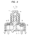
- Fig. 3 is a first explanatory drawing for explaining first operation of the switch according to the invention
- Fig. 4 is a second explanatory drawing for explaining second operation of the switch according to the invention
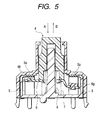
- Fig. 5 is a third explanatory drawing for explaining third operation of the switch according to the invention.
- the switch is turned on because the first contact 6g and the second contact 6h of the moving contact 6 are elastically touched to each fixed contact 5a of the fixed terminal 5.
- the operating shaft 4 of the switch is moved (pressed) by approximately 2 mm for example in a direction shown by an arrow A as shown in Fig. 3 from this state.
- the movement in the direction shown by the arrow A is made against the spring of the first coil spring 7 and the second coil spring 8.
- a part of the lower end face of the base 4a of the operating shaft 4 is touched to the bent part 6k between the base 6a of the moving contact 6 and the first arm 6b by the movement of the operating shaft 4, the base 6a of the moving contact 6 is moved (pushed down) and the first contact 6g made of noble metal of the moving contact 6 is earlier separated from the fixed contact 5a of one fixed terminal 5 by the movement of the base 6a.
- the switch is turned off by the separation from the fixed contact 5a of the first contact 6g.
- the separation from the fixed contact 5a of the first contact 6g causes so-called arc discharge when comparatively large direct current flows in the switch, however, as the first contact 6g is made of noble metal, the damage of the first contact 6g by arc discharge is small.
- the operating shaft 4 of the switch is further moved (pressed) by approximately 3 mm for example in the direction shown by the arrow A.
- the movement in the direction shown by the arrow A is made against the spring of the first coil spring 7 and the second coil spring 8.
- the base 6a of the moving contact 6 is further moved (pushed down) by the movement of the operating shaft 4 of the total approximately 5 mm (approximately 2 mm + approximately 3 mm) and the second contact 6h of the moving contact 6 is separated from the fixed contact 5a of the other fixed terminal 5 by the further parallel movement of the base 6a.
- the moving contact 6 of the switch is securely separated from a pair of fixed terminals 5 by the separation of the second contact 6h from the fixed contact 5a and is completely turned off.
- the base 6a of the moving contact 6 is arranged in a position parallel to each fixed contact 5a of the fixed terminals 5.
- the operating shaft 4 of the switch is moved (returned) by approximately 1.5 mm for example in a direction shown by an arrow B as shown in Fig. 5.
- the movement in the direction shown by the arrow B is made by the self-restitutive force of the first coil spring 7 and the second coil spring 8.
- One end of the pin 9 shown in Fig. 1 is fitted into a predetermined location of the cam concave 4e shown in Fig. 1 forming the heart cam by the movement and the operating shaft 4 remains in a location moved (returned) by approximately 1.5 mm.
- the second contact 6h is earlier touched to the fixed contact 5a.
- the switch is turned off, no arc discharge is caused between the fixed contact 5a and the second contact 6h.
- the operating shaft 4 is further moved in the direction shown by the arrow B from the state shown in Fig. 3 and is returned to the initial position shown in Fig. 2.
- the first contact 6g is touched to the fixed contact 5a and the switch is turned on.
- the invention provides the switch which can be formed using high-priced material for only the first contact on one side, which is low-priced and the stable long life of which can be also achieved by the switching operation of heavy-current by earlier separating the first contact made of noble metal of the moving contact from the fixed contact of the fixed terminal than the second contact by touching the end of the operating shaft to the moving contact and further pushing down the operating shaft against the pressure of the first coil spring and later touching the first contact of the moving contact to the fixed contact of the fixed terminal than the second contact by the pressure of the first coil spring by returning the operating shaft.
- the configuration of the switch according to the invention is simplified and the switch can be low-priced because the moving contact is formed of a flat plate, the first arm in which the first contact is provided is bent downward in the bent part for the base, the base is inclined in relation to the fixed contact, the bent part is the closest to the end of the operating shaft and the first and second contacts are elastically touched to each fixed contact respectively by the pressure of the first coil spring on the base of the moving contact.
- the invention can provide the switch the space of which can be effectively utilized and which is small-sized because the second coil spring pierces the hole of the moving contact, is arranged coaxially with the first coil spring inside the first coil spring and presses the operating shaft upward in the axial direction of the operating shaft.
- the invention can provide the switch in which the first and second coil springs and the operating shaft can be easily positioned because the strut perpendicularly extended from the bottom wall of the body is provided, the first and the second coil springs are provided along the strut and the operating shaft is arranged at the end of the strut so that it can be moved upward or downward in the axial direction.
- the body of the switch according to the invention is composed of the upper case and the lower case, the lower case has the opposite side walls, a pair of opposite convexes are formed on the sides of each open end of the side walls and the efficiency of the assembly operation is enhanced by temporarily tacking the moving contact pressed by the first coil spring in the lower case by fitting both ends of the moving contact to a pair of convexes.
Landscapes
- Push-Button Switches (AREA)
- Contacts (AREA)
Abstract
Description
a body, an operating shaft housed in the body, a moving contact arranged in the body so that it is moved in an axial direction of the operating shaft, a pair of fixed terminals arranged in the body so that they are located over the moving contact and a first coil spring housed on the side of a bottom wall of the body so that it presses the moving contact upward in the axial direction of the operating shaft and is characterized in that the moving contact is provided with first and second contacts provided at both ends, the first contact is made of noble metal, a pair of fixed terminals are respectively provided with a fixed contact, the first and second contacts are touched to each fixed contact by pressure on the moving contact by the first coil spring, touching an end of the operating shaft to the moving contact by moving the operating shaft downward in the axial direction, and the first contact of the moving contact is separated from the fixed contact of the fixed terminal earlier than the second contact by further pushing down the operating shaft against the pressure of the first coil spring and the first contact of the moving contact is touched to the fixed contact of the fixed terminal later than the second contact by the pressure of the first coil spring by returning the operating shaft.
characterized in that the moving contact is formed by a flat plate and is composed of a base substantially in a center and first and second arms at both ends, the first arm in which the first contact is provided is bent downward in a bent part in relation to the base and the first and second contacts are touched to each of the fixed contacts by inclining the base in relation to the fixed contact and most approaching the bent part to an end of the operating shaft by the pressure of the first coil spring on the base of the moving contact.
characterized in that a hole is formed in a center of the moving contact, the second coil spring pierces the hole of the moving contact, the second coil spring is arranged coaxially with the first coil spring inside the first coil spring and the second coil spring presses the operating shaft upward in the axial direction of the operating shaft.
characterized in that a strut perpendicularly extended from the bottom wall is provided on the bottom wall of the body, the first and second coil springs are provided along the strut and the operating shaft is arranged at an end of the strut so that the operating shaft can be moved upward or downward in the axial direction.
with a body, an operating shaft housed in the body, a moving contact arranged in the body so that the moving contact is moved in an axial direction of the operating shaft, a pair of fixed terminals arranged in the body so that they are positioned over the moving contact and a first coil spring housed on the side of a bottom wall of the body so that it presses the moving contact upward in the axial direction of the operating shaft and is also characterized in that the body is composed of an upper case and a lower case, the lower case has opposite side walls, a pair of opposite convexes are formed on sides of each open end of the side walls, the moving contact pressed by the first coil spring is temporarily tacked in the lower case by fitting both ends of the moving contact to a pair of convexes, the fixed terminal is attached to the lower case from the upside of the moving contact, fitting between one of a pair of convexes and the moving contact is released by elastically pressing the fixed terminal on the moving contact against the pressure of the first coil spring, the upper case covers the lower case from a side of the open end, an end of the operating shaft touches to the moving contact by moving the operating shaft downward in the axial direction, and the moving contact is separated from the fixed terminal by further pushing down the operating shaft against the pressure of the first coil spring and the moving contact is touched to the fixed terminal by the pressure of the first coil spring by returning the operating shaft.
Claims (5)
- A switch, comprising:a body;an operating shaft housed in the body;a moving contact arranged in the body so that the moving contact is moved in an axial direction of the operating shaft;a pair of fixed terminals arranged in the body so that they are positioned over the moving contact; anda first coil spring housed on the side of a bottom wall of the body so that it presses the moving contact upward in the axial direction of the operating shaft, whereinthe moving contact is provided with first and second contacts provided at both ends, andthe first contact is made of noble metal, anda pair of fixed terminals are respectively provided with a fixed contact,the first and second contacts are touched to each fixed contact by pressure of the first coil spring on the moving contact, andwhen the operating shaft moves downward in the axial direction an end of the operating shaft touches to the moving contact, and further when the operating shaft is pushed down against the pressure of the first coil spring, the first contact of the moving contact is separated from the fixed contact of the fixed terminal earlier than the second contact, and when the operating shaft returns the first contact of the moving contact is touched to the fixed contact of the fixed terminal later than the second contact by the pressure of the first coil spring.
- A switch according to Claim 1, wherein
the moving contact is formed by a flat plate and is composed of a base substantially in a center and first and second arms at both ends, and
the first arm in which the first contact is provided is bent downward in a bent part in relation to the base, and
the first and second contacts are touched to each of the fixed contacts by inclining the base in relation to the fixed contact and most approaching the bent part to an end of the operating shaft by the pressure of the first coil spring on the base of the moving contact. - A switch according to Claim 1 or 2, wherein
a hole is formed in a center of the moving contact, wherein
the second coil spring pierces the hole of the moving contact, and
the second coil spring is arranged coaxially with the first coil spring inside the first coil spring, and
the second coil spring presses the operating shaft upward in the axial direction of the operating shaft. - A switch according to Claim 3, wherein
a strut perpendicularly extended from the bottom wall is provided on the bottom wall of the body, and
the first and second coil springs are provided along the strut, and
the operating shaft is arranged at an end of the strut so that the operating shaft can be moved upward or downward in the axial direction. - A switch, comprising:a body;an operating shaft housed in the body;a moving contact arranged in the body so that the moving contact is moved in an axial direction of the operating shaft;a pair of fixed terminals arranged in the body so that they are positioned over the moving contact; anda first coil spring housed on the side of a bottom wall of the body so that it presses the moving contact upward in the axial direction of the operating shaft, whereinthe body is composed of an upper case and a lower case, andthe lower case has opposite side walls, anda pair of opposite convexes are formed on sides of each open end of the side walls, andthe moving contact pressed by the first coil spring is temporarily tacked in the lower case by fitting both ends of the moving contact to a pair of convexes, andthe fixed terminal is attached to the lower case from the upside of the moving contact, andfitting between one of a pair of convexes and the moving contact is released by pressing the fixed terminal on the moving contact against the pressure of the first coil spring, andthe upper case covers the lower case from a side of the open end, andan end of the operating shaft touches to the moving contact by moving the operating shaft downward in the axial direction, and the moving contact is separated from the fixed terminal by further pushing down the operating shaft against the pressure of the first coil spring, andthe moving contact is touched to the fixed terminal by the pressure of the first coil spring by returning the operating shaft.
Priority Applications (1)
| Application Number | Priority Date | Filing Date | Title |
|---|---|---|---|
| EP03020782A EP1372169B1 (en) | 2000-12-14 | 2001-12-14 | Push-button switch for switching heavy-current |
Applications Claiming Priority (2)
| Application Number | Priority Date | Filing Date | Title |
|---|---|---|---|
| JP2000384914 | 2000-12-14 | ||
| JP2000384914A JP3964132B2 (en) | 2000-12-14 | 2000-12-14 | Switch device |
Related Child Applications (1)
| Application Number | Title | Priority Date | Filing Date |
|---|---|---|---|
| EP03020782A Division EP1372169B1 (en) | 2000-12-14 | 2001-12-14 | Push-button switch for switching heavy-current |
Publications (3)
| Publication Number | Publication Date |
|---|---|
| EP1215692A2 true EP1215692A2 (en) | 2002-06-19 |
| EP1215692A3 EP1215692A3 (en) | 2002-07-10 |
| EP1215692B1 EP1215692B1 (en) | 2004-05-12 |
Family
ID=18852276
Family Applications (2)
| Application Number | Title | Priority Date | Filing Date |
|---|---|---|---|
| EP03020782A Expired - Lifetime EP1372169B1 (en) | 2000-12-14 | 2001-12-14 | Push-button switch for switching heavy-current |
| EP01129866A Expired - Lifetime EP1215692B1 (en) | 2000-12-14 | 2001-12-14 | Push-Push switch for switching heavy-current |
Family Applications Before (1)
| Application Number | Title | Priority Date | Filing Date |
|---|---|---|---|
| EP03020782A Expired - Lifetime EP1372169B1 (en) | 2000-12-14 | 2001-12-14 | Push-button switch for switching heavy-current |
Country Status (4)
| Country | Link |
|---|---|
| US (1) | US6605792B2 (en) |
| EP (2) | EP1372169B1 (en) |
| JP (1) | JP3964132B2 (en) |
| DE (2) | DE60103235T2 (en) |
Cited By (2)
| Publication number | Priority date | Publication date | Assignee | Title |
|---|---|---|---|---|
| CN101271792A (en) * | 2008-04-18 | 2008-09-24 | 方安林 | Push-button contact switch |
| CN106158479A (en) * | 2014-12-29 | 2016-11-23 | 余正明 | Keyboard switch |
Families Citing this family (11)
| Publication number | Priority date | Publication date | Assignee | Title |
|---|---|---|---|---|
| US6791038B1 (en) * | 2003-11-25 | 2004-09-14 | Defond Components Limited | Electrical switch |
| JP4456521B2 (en) * | 2005-04-28 | 2010-04-28 | 株式会社テーアンテー | Automotive push switch |
| JP4779705B2 (en) * | 2006-02-28 | 2011-09-28 | パナソニック株式会社 | Push switch for vehicle |
| JP4800231B2 (en) * | 2007-02-02 | 2011-10-26 | 東京パーツ工業株式会社 | Push switch mechanism |
| DE102007015793B4 (en) * | 2007-03-30 | 2009-02-05 | Siemens Ag | Contact slide unit for a switching unit, in particular a circuit breaker. |
| JP5802078B2 (en) * | 2011-08-10 | 2015-10-28 | 株式会社ヴァレオジャパン | Push switch |
| US9443670B2 (en) * | 2012-06-05 | 2016-09-13 | Illinois Tool Works, Inc. | Contamination resistant push button switch |
| CN103280358B (en) * | 2013-06-04 | 2015-09-09 | 科都电气有限公司 | Direct current speed adjustment switch |
| US20160071662A1 (en) * | 2014-09-05 | 2016-03-10 | Dongguan Zen-tech Electronic Technology Co., Ltd. | Keyboard switch |
| DE102017223250A1 (en) | 2017-12-19 | 2019-06-19 | Siemens Aktiengesellschaft | Motor starter, operating method, computer program product and motor starter arrangement |
| JP2019185957A (en) * | 2018-04-05 | 2019-10-24 | 株式会社東海理化電機製作所 | Contact device |
Family Cites Families (7)
| Publication number | Priority date | Publication date | Assignee | Title |
|---|---|---|---|---|
| US3040142A (en) | 1959-10-22 | 1962-06-19 | Arrow Hart & Hegeman Electric | Lighted push button starting switch |
| DE2737221A1 (en) * | 1977-08-18 | 1979-02-22 | Kirsten Elektrotech | Switch for motor vehicle brake light - has sliding contact bridge on plunger end strip with copper contact rivet for cooperation with terminal contact |
| JPS60147032U (en) * | 1984-03-08 | 1985-09-30 | アルプス電気株式会社 | switch |
| US4968860A (en) * | 1988-05-19 | 1990-11-06 | Omron Tateisi Electronics Co. | Light emitting type push button switch |
| JP3109635B2 (en) | 1993-09-17 | 2000-11-20 | アルプス電気株式会社 | Plunger switch |
| EP0851447A1 (en) * | 1996-12-30 | 1998-07-01 | TRW SIPEA S.p.A. | Automotive switching device with an antinoise filter, particulary for controlling stop lights |
| US6335500B1 (en) * | 2000-11-01 | 2002-01-01 | Ching-Yu Chi | Push button type of switch |
-
2000
- 2000-12-14 JP JP2000384914A patent/JP3964132B2/en not_active Expired - Fee Related
-
2001
- 2001-12-14 DE DE60103235T patent/DE60103235T2/en not_active Expired - Fee Related
- 2001-12-14 EP EP03020782A patent/EP1372169B1/en not_active Expired - Lifetime
- 2001-12-14 US US10/020,271 patent/US6605792B2/en not_active Expired - Lifetime
- 2001-12-14 EP EP01129866A patent/EP1215692B1/en not_active Expired - Lifetime
- 2001-12-14 DE DE60109068T patent/DE60109068T2/en not_active Expired - Lifetime
Cited By (6)
| Publication number | Priority date | Publication date | Assignee | Title |
|---|---|---|---|---|
| CN101271792A (en) * | 2008-04-18 | 2008-09-24 | 方安林 | Push-button contact switch |
| CN101271792B (en) * | 2008-04-18 | 2014-05-14 | 方安林 | Push-button contact switch |
| CN106158479A (en) * | 2014-12-29 | 2016-11-23 | 余正明 | Keyboard switch |
| CN106158481A (en) * | 2014-12-29 | 2016-11-23 | 余正明 | Keyboard switch |
| CN106158470A (en) * | 2014-12-29 | 2016-11-23 | 余正明 | Keyboard switch |
| CN106158478A (en) * | 2014-12-29 | 2016-11-23 | 余正明 | Keyboard switch |
Also Published As
| Publication number | Publication date |
|---|---|
| DE60103235T2 (en) | 2005-05-04 |
| EP1215692B1 (en) | 2004-05-12 |
| JP3964132B2 (en) | 2007-08-22 |
| DE60103235D1 (en) | 2004-06-17 |
| US20020092756A1 (en) | 2002-07-18 |
| EP1372169B1 (en) | 2005-02-23 |
| EP1215692A3 (en) | 2002-07-10 |
| JP2002184262A (en) | 2002-06-28 |
| EP1372169A1 (en) | 2003-12-17 |
| US6605792B2 (en) | 2003-08-12 |
| DE60109068T2 (en) | 2005-06-30 |
| DE60109068D1 (en) | 2005-03-31 |
Similar Documents
| Publication | Publication Date | Title |
|---|---|---|
| EP1215692B1 (en) | Push-Push switch for switching heavy-current | |
| US6222144B1 (en) | Pushbutton switch | |
| JP2003272474A (en) | Push switch | |
| JP2003297183A (en) | Slide switch and manufacturing method thereof | |
| US6861595B2 (en) | Contact block assembly and a method for assembling the same | |
| US5278370A (en) | Push switch | |
| CN110024070A (en) | push switch | |
| US6689967B2 (en) | Slide switch | |
| US4055736A (en) | Push switch | |
| EP1014405B1 (en) | Push switch | |
| US4280027A (en) | Switch blade mechanism and multi-arrangement | |
| US5973284A (en) | Push button switch assembly with snap action movable bridging contact | |
| JP4508957B2 (en) | Push button switch | |
| US20060037851A1 (en) | Side push switch | |
| JP4721874B2 (en) | Slide operation switch | |
| EP1918957A1 (en) | A surface-mounted switch | |
| JP2589914Y2 (en) | switch | |
| JPH0730428U (en) | switch | |
| JP2003068164A (en) | Switch | |
| JPH0313943Y2 (en) | ||
| JP4209222B2 (en) | Push button switch | |
| JP2001250450A (en) | Push button switch | |
| JP4153052B2 (en) | Push button switch | |
| JP2548307Y2 (en) | Push button switch | |
| JPH0310584Y2 (en) |
Legal Events
| Date | Code | Title | Description |
|---|---|---|---|
| PUAI | Public reference made under article 153(3) epc to a published international application that has entered the european phase |
Free format text: ORIGINAL CODE: 0009012 |
|
| PUAL | Search report despatched |
Free format text: ORIGINAL CODE: 0009013 |
|
| AK | Designated contracting states |
Kind code of ref document: A2 Designated state(s): AT BE CH CY DE DK ES FI FR GB GR IE IT LI LU MC NL PT SE TR |
|
| AX | Request for extension of the european patent |
Free format text: AL;LT;LV;MK;RO;SI |
|
| AK | Designated contracting states |
Kind code of ref document: A3 Designated state(s): AT BE CH CY DE DK ES FI FR GB GR IE IT LI LU MC NL PT SE TR |
|
| AX | Request for extension of the european patent |
Free format text: AL;LT;LV;MK;RO;SI |
|
| 17P | Request for examination filed |
Effective date: 20020813 |
|
| AKX | Designation fees paid |
Designated state(s): DE FR GB SE |
|
| 17Q | First examination report despatched |
Effective date: 20030422 |
|
| GRAP | Despatch of communication of intention to grant a patent |
Free format text: ORIGINAL CODE: EPIDOSNIGR1 |
|
| GRAA | (expected) grant |
Free format text: ORIGINAL CODE: 0009210 |
|
| GRAS | Grant fee paid |
Free format text: ORIGINAL CODE: EPIDOSNIGR3 |
|
| AK | Designated contracting states |
Kind code of ref document: B1 Designated state(s): DE FR GB SE |
|
| REG | Reference to a national code |
Ref country code: GB Ref legal event code: FG4D |
|
| REG | Reference to a national code |
Ref country code: IE Ref legal event code: FG4D |
|
| REF | Corresponds to: |
Ref document number: 60103235 Country of ref document: DE Date of ref document: 20040617 Kind code of ref document: P |
|
| REG | Reference to a national code |
Ref country code: SE Ref legal event code: TRGR |
|
| ET | Fr: translation filed | ||
| PGFP | Annual fee paid to national office [announced via postgrant information from national office to epo] |
Ref country code: SE Payment date: 20041206 Year of fee payment: 4 |
|
| PGFP | Annual fee paid to national office [announced via postgrant information from national office to epo] |
Ref country code: FR Payment date: 20041221 Year of fee payment: 4 |
|
| PGFP | Annual fee paid to national office [announced via postgrant information from national office to epo] |
Ref country code: DE Payment date: 20050222 Year of fee payment: 4 |
|
| PLBE | No opposition filed within time limit |
Free format text: ORIGINAL CODE: 0009261 |
|
| STAA | Information on the status of an ep patent application or granted ep patent |
Free format text: STATUS: NO OPPOSITION FILED WITHIN TIME LIMIT |
|
| 26N | No opposition filed |
Effective date: 20050215 |
|
| PG25 | Lapsed in a contracting state [announced via postgrant information from national office to epo] |
Ref country code: GB Free format text: LAPSE BECAUSE OF NON-PAYMENT OF DUE FEES Effective date: 20051214 |
|
| PG25 | Lapsed in a contracting state [announced via postgrant information from national office to epo] |
Ref country code: SE Free format text: LAPSE BECAUSE OF NON-PAYMENT OF DUE FEES Effective date: 20051215 |
|
| PG25 | Lapsed in a contracting state [announced via postgrant information from national office to epo] |
Ref country code: DE Free format text: LAPSE BECAUSE OF NON-PAYMENT OF DUE FEES Effective date: 20060701 |
|
| EUG | Se: european patent has lapsed | ||
| GBPC | Gb: european patent ceased through non-payment of renewal fee |
Effective date: 20051214 |
|
| PG25 | Lapsed in a contracting state [announced via postgrant information from national office to epo] |
Ref country code: FR Free format text: LAPSE BECAUSE OF NON-PAYMENT OF DUE FEES Effective date: 20060831 |
|
| REG | Reference to a national code |
Ref country code: FR Ref legal event code: ST Effective date: 20060831 |