Technical Field
The present invention relates to apparatus for
generating a radioisotope.
Background Art
The radioisotopes are utilized as radiation
sources and tracers in various fields. Particularly,
artificial radioisotopes are expected to be used as
medical tracers in positron CT (PET) and others.
The radioisotopes used as medical tracers are
selected from those with relatively short life in
consideration of effects on organisms and, for example,
biological constituent elements such as 11C, 13N, and 15O,
and 18F are used in practice. These radioisotopes are
able to be produced by accelerators, nuclear reactors,
and laser nuclear fusion systems and, for example, the
radioisotopes for PET are mainly produced by cyclotron
accelerators.
Disclosure of the Invention
However, since the conventional radioisotope
generators as described above had large instrumental
scale, they required a large space at an installation
site and thus posed the problem that they were unable
to be installed so as to suit facilities utilizing the
generated radioisotopes. Namely, it was difficult to
install a generator in a limited space in medical
facilities and the like and permit free use at
necessary occasions. Reasons for it are that these
generators require a large space for the reactor in
terms of the principle and that large shielding
facilities are necessary for radiations generated from
the whole of the large reactor.
In particular, on the occasion of generating and
utilizing a radioisotope with relatively short life,
the radioisotope should be ideally used at the same
time as the generation thereof. Accordingly, the
radioisotope cannot be effectively utilized unless the
generator is directly coupled to the utilizing
facilities because of its large scale. Even if the
generator can be directly coupled to the utilizing
facilities, the reactor occupying the large space will
make it difficult to collect the generated radioisotope
quickly and utilize it efficiently.
Further, since these generators had the large
scale and were normally operated under continuous
operating conditions, they involved the problem of
increase in construction cost, cost necessary for
maintenance, and needless running cost.
It is an object of the present invention, which
has been accomplished in view of the above problems, to
provide compact, low-cost radioisotope generating
apparatus that can be installed on-site at the
utilizing facilities.
A radioisotope generating apparatus according to
the present invention comprises a nuclear reaction
section an interior of which is retained in a vacuum; a
source supply section for supplying a source material
consisting of a nuclide necessary for generation of a
radioisotope, to the nuclear reaction section; an
optical system for irradiating the source material
supplied into the nuclear reaction section and thereby
brought into a dispersed state, with pulse laser light,
thereby inducing a nuclear reaction in the source
material to generate the radioisotope; a product
nucleus collecting section for collecting a molecule
having a nucleus of the radioisotope generated in the
nuclear reaction section; and a radiation shielding
system for preventing outside leakage of radiations
generated in the nuclear reaction section.
According to the present invention, the reaction
field where the source material supplied from the
source supply section experiences the desired nuclear
reaction is formed in a small irradiated region with
the pulse laser light of high peak power emitted from
the optical system. In addition, this reaction field
is fixed at a selected position in the nuclear reaction
section by determining the position of the supply port
of the source material and the irradiated position with
the pulse laser light. Accordingly, the spaces
necessary for the nuclear reaction section and for the
radiation shielding system can be much smaller than
those in the conventional apparatus and, in turn, the
scale of the entire generating apparatus can be made
compact. Further, since the radioisotope generating
apparatus according to the present invention is compact,
it can be readily used in a direct coupled state to the
utilizing facilities, and the radioisotope generated in
the nuclear reaction section can be quickly collected
by the product nucleus collecting section to be
utilized efficiently.
The term "vacuum" herein represents a degree of
vacuum in which the desired nuclear reaction can take
place with little influence of inhibition due to
impurities except for the foregoing source material.
Therefore, the vacuum is by no means limited, for
example, to scientific high vacuums (1 × 10⁻⁶ to 1 ×
10-2 Pa), but it can also be either one of so-called
ultra-high vacuums and extra-high vacuums.
Preferably, the radioisotope generating apparatus
of the present invention further comprises a nuclear
reaction monitor section for monitoring reaction
product particles in the nuclear reaction section; and
a nuclear reaction control section for controlling a
supply condition of the source material in the source
supply section, based on output of the nuclear reaction
monitor section. This permits the nuclear reaction to
be controlled more precisely, so that the radioisotope
can be generated more efficiently.
The "reaction product particles" herein indicate
all particles generated in the nuclear reaction in the
nuclear reaction section and are properly selected from
nuclei, protons, neutrons, electrons, positrons,
photons, and so on.
Brief Description of the Drawings
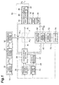
Fig. 1 is a block diagram of a radioisotope
generating apparatus according to an embodiment of the
present invention.
Fig. 2 is a block diagram to show a specific
configuration of the radioisotope generating apparatus
of Fig. 1.
Fig. 3 is a block diagram to show another
specific configuration of the radioisotope generating
apparatus.
Best Mode for Carrying out the Invention
Preferred embodiments of the present invention
will be described below in detail with reference to the
drawings. Throughout the drawings, identical or
equivalent portions will be denoted by the same
reference symbols.
Fig. 1 shows the block structure of a preferred
embodiment of the radioisotope generating apparatus
according to the present invention. Fig. 2 shows a
more specific configuration of the radioisotope
generating apparatus of Fig. 1.
As shown in Fig. 1, the radioisotope generating
apparatus of the present embodiment is comprised of a
nuclear reaction section 30 the interior of which is
retained in a vacuum; a source supply section 20 for
supplying a source material R consisting of a nuclide
necessary for generation of a radioisotope, to the
nuclear reaction section 30; an optical system 10 for
irradiating the source material R supplied into the
nuclear reaction section 30 and thereby brought into a
dispersed state, with pulse laser light, thereby
inducing a nuclear reaction in the source material R to
generate the radioisotope; a product nucleus collecting
section 40 for collecting molecules PI having nuclei of
the radioisotope generated in the nuclear reaction
section; a radiation shielding system 50 for preventing
outside leakage of radiations generated in the nuclear
reaction section 30; a nuclear reaction monitor section
60 for monitoring reaction product particles PX in the
nuclear reaction section 30; and a nuclear reaction
control section 70 for controlling a supply condition
of the source material R in the source supply section
20, based on output of the nuclear reaction monitor
section 60.
Each of the above components will be detailed
below on the basis of Fig. 1 showing the block
structure and Fig. 2 showing the more specific
configuration.
As shown in Fig. 1, the optical system 10 is
comprised of a light source section 12 for emitting the
pulse laser light L12 of high peak power; a lightguide
optical system 14 for guiding the output light L12 from
the light source section 12 to a desired position and
in a desired orientation without degradation of optical
characteristics thereof due to dispersion or the like
to emit output light L14; and an irradiating optical
system 16 for amplifying optical intensity and density
of the output light L14 from the lightguide optical
system 14 and emitting output light L10 toward the
interior of the nuclear reaction section 30. Since
this output light L10 is the pulse laser light of high
peak power, the field of nuclear reaction is limited to
only a small region irradiated with the output light
L10. Namely, thanks to the pulse laser light L10 of
high peak power, the reaction field of the desired
nuclear reaction can be formed in the small region that
is always spatially defined. This small region where
the desired nuclear reaction occurs will be referred to
hereinafter as "nucleus generating region F."
The light source section 12 is constructed using
a titanium-sapphire laser system to emit the pulse
laser light L12 of high peak power having the
wavelength of 800 nm, the pulse width of 30 fs, and the
energy per pulse of 200 mJ. The pulse laser light
having such properties can be generated by known pulse
amplification methods. This titanium-sapphire laser
system can be constructed even in the table top size.
As shown in Fig. 2, the lightguide optical system
14 is comprised of reflecting optical elements such as
plane reflectors, concave mirrors, off-axis parabolic
reflectors, or the like which are fully resistant to
the pulse laser light. By a combination of these
reflecting optical elements, the optical system can
propagate the output light L12 from the light source
section 12 without degradation of the optical
characteristics thereof due to dispersion or the like.
This is effective, particularly, in the case wherein
the irradiating optical system 16 is located at a
position where the output light L12 from the light
source section 12 cannot be directly guided to the
irradiating optical system 16, because of the structure
of the apparatus.
As shown in Fig. 2, the irradiating optical
system 16 is also comprised of reflecting optical
elements similar to the lightguide optical system 14.
By a combination of these reflecting optical elements,
the irradiating optical system 16 can implement
convergence and the like of the output light L14 from
the lightguide optical system 14, thereby amplifying
the optical intensity and density of the output light
L14 from the lightguide optical system 14. If the
influence of dispersion and others is negligible, the
light may be converged by transmitting optical elements
such as lenses and the like.
It is also possible to incorporate part or the
whole of the optical system 10 into the nuclear
reaction section 30 as occasion demands. This
configuration is effective in the case wherein the
output light L10 from the optical system 10 has the
peak power insufficient to be supplied as stable output
light in air and in the case wherein the output light
L10 is converged within a very short distance to
decrease the size of the converged spot, thereby
yielding a high power density.
As shown in Fig. 1, the source supply section 20
is comprised of a source reservoir 22 in which a fixed
amount of the source material R is reserved; a source
spray section 28 for supplying the source material R
from the source reservoir 22 by spraying it into the
nuclear reaction section 30; a temperature setting
section 24 for setting the temperature of the source
material R sprayed from the source spray section 28;
and a pressure setting section 26 for setting the
pressure of the source material R sprayed from the
source spray section 28, and has such structure as to
hermetically seal in the source completely except for
an outlet of the source spray section 28. By these,
the source material R is set at the temperature and
pressure suitable for induction of the desired nuclear
reaction and is accurately sprayed into the nucleus
generating region F being the small reaction field
formed in the nuclear reaction section 30.
The source material R is properly selected and
used from materials consisting of a nuclide necessary
for generation of a desired radioisotope. Particularly,
for obtaining the radioisotopes used as medical tracers,
it is effective to use water as a source material.
Reasons for it are that natural water fully contains
16O and 1H necessary for synthesis of 13N and that there
is no need for extra purification. A stainless steel
vessel or the like is used as the source reservoir 22
for reserving the source material R and the internal
wall surface of the vessel is properly treated by a
surface treatment such as a teflon coating or the like
in consideration of the chemical properties of the
source material R employed and an operation temperature
range. This source reservoir 22 is directly coupled to
the source spray section 28 by a stainless steel pipe.
As shown in Fig. 2, the temperature setting
section 24 is comprised of a heater 24a employing a
nichrome wire or the like, and a current source 24b for
supplying an electric current to the heater 24a to
generate heat. This heater 24a is wound, particularly,
over the source spray section 28 and generates heat
under the supply of the electric current from the
current source 24b to retain the source spray section
28 at a desired temperature. By this structure, the
source material R in the source spray section 28 is set
at the desired temperature and is sprayed as a gas jet
from the outlet. The heater is also wound around such
portions as the source reservoir 22 and the pressure
setting section 26 except for meters to control the
temperature in order to keep the temperature of the
source material R uniform as occasion demands.
Particularly, where the source material R before
sprayed needs to be completely vaporized, or the like,
the source supply section 20 is totally heated so as to
prevent the source material R from condensing in the
temperature setting section 24.
The pressure setting section 26 is provided with
a booster pump, and this booster pump is directly
coupled to the source spray section 28 by a stainless
steel pipe. This allows the source material R to be
sprayed under a desired pressure from the outlet of the
source spray section 28. Since the interior of the
source supply section 20 is hermetically sealed in, the
booster pump does not always have to be provided if the
sufficient pressurization effect is achieved by
expansion of the source material R heated by the
temperature setting section 24.
As shown in Fig. 2, the source spray section 28
is provided with a gas valve 28a having the diameter of
about 2 mm in the outlet part and is arranged to
project the outlet part into the nuclear reaction
section 30. This gas valve 28a is equipped with a
position adjusting mechanism 28b capable of moving the
spray position of the source material R. For
controlling this position adjusting mechanism 28b, a
spray position controller 28f is provided outside the
nuclear reaction section 30 and is electrically
connected to the position adjusting mechanism 28b. The
outlet port at the distal end of the gas valve 28a is
equipped with electromagnetic shutter 28c and gas jet
nozzle 28d. This electromagnetic shutter 28c is
constructed to open and close by an applied voltage
from the outside. For this purpose, an applied voltage
controller 28e for controlling the applied voltage to
the electromagnetic shutter 28c is disposed outside the
nuclear reaction section 30 and electrically connected
to the gas valve 28a.
By this position adjusting mechanism 28b, the
source material R is able to be readily introduced into
the nucleus generating region F where the nuclear
reaction occurs efficiently in the nuclear reaction
section 30. Since the provision of the electromagnetic
shutter 28c permits the source material R to be sprayed
in agreement with the irradiation timing of the output
light L10 from the optical system 10 guided into the
nuclear reaction section 30, it is feasible to bring
about the nuclear reaction efficiently and reduce the
load on a vacuum pump 34 provided in order to keep the
nuclear reaction section 30 in a vacuum.
Concerning the source supply section 20, it is
also possible to incorporate part or the whole of the
source supply section 20, as well as the source spray
section 28, into the nuclear reaction section 30.
As shown in Fig. 1, the nuclear reaction section
30 is comprised of a vacuum chamber 32, a vacuum pump
34 for keeping the interior of the vacuum chamber 32 in
a high vacuum, and a vacuum gage 36. These permit the
reaction field of nuclear reaction to be retained under
the high vacuum condition.
The vacuum chamber 32 is a stainless steel
chamber adapted for high vacuums. The vacuum chamber
32 is provided with an optical window W10 of quartz
coated with antireflection coatings on the both
surfaces thereof for incidence of the output light L10
from the optical means 10. This quartz optical window
W10 has a sufficient transmittance suitable for the
wavelength of the output light L10 from the optical
means 10 and is also fully resistant to the intensity
of the output light L10. The quartz optical window W10
is provided with the antireflection coatings on the
both surfaces and is arranged at the Brewster angle to
polarization of the output light L10. By this
arrangement, the output light L10 is converged more
efficiently in the vacuum chamber 32.
This quartz optical window W10 is set at a
determined position in the vacuum chamber 32, whereby
the irradiated region with the output light L10 from
the optical means 10 is almost fixed in the vacuum
chamber 32. Further, the outlet part of the source
spray section 28 in the source supply section 20 is
arranged to be inserted in the vacuum chamber 32, so
that the spray position of the source material R can be
adjusted so as to agree with the irradiated region with
the output light L10 from the optical means 10. By this
arrangement, the nucleus generating region F where the
nuclear reaction occurs efficiently is formed in the
small region that is always defined in the vacuum
chamber 32. This permits the size of the vacuum
chamber 32 to be set small within the range where the
meters set inside are not damaged by the nuclear
reaction, and, in turn, the scale of the entire reactor
can be largely decreased as compared with the
conventional reactors.
As shown in Fig. 2, the vacuum pump 34 is
comprised of a turbo-molecular pump 34a having the
exhaust rate of 600 l/s, and a rotary pump 34b. The
turbo-molecular pump 34a is directly coupled to the
vacuum chamber 32 by a pipe adapted for high vacuums
and the rotary pump 34b is directly coupled similarly
through a vacuum valve 34c to the exhaust side of the
turbo-molecular pump 34a. By this vacuum pump 34, the
interior of the vacuum chamber can also be maintained
in the high vacuum of about 1 × 10⁻³ Pa even during the
spraying of the source material R.
The vacuum gage 36 is an ionization gage. This
can directly measure the degree of vacuum inside the
vacuum chamber 32. This vacuum gage 36 is located at a
position where it can directly measure the degree of
vacuum inside the vacuum chamber 32 and where it is not
directly hit by the source material R sprayed from the
source spray section 28. In the present embodiment the
vacuum gage is set in a peripheral area of an intake
port of the vacuum pump 34 in the vacuum chamber 32.
As shown in Fig. 2, the product nucleus
collecting section 40 is comprised of a vacuum valve
42a directly coupled to the vacuum chamber 32; a
molecule reservoir 44 for collecting and temporarily
storing molecules PI having the nuclei of the
radioisotope generated in the vacuum chamber 32 via the
vacuum valve 42a; a vacuum valve 42b provided on the
exit side of the molecule reservoir 44; and a molecule
collecting pipe 46 for guiding the molecules PI having
the nuclei of the radioisotope, stored in the molecule
reservoir 44, to the external utilizing facilities.
This product nucleus collecting section 40 can be
disconnected independently from the nuclear reaction
section 30 by the vacuum valve 42a and can also be
disconnected independently from the radioisotope
utilizing facilities by the vacuum valve 42b. This
product nucleus collecting section 40 directly guides
the molecules PI of the radioisotope collected in the
molecule reservoir 44, through the molecule collecting
pipe 46 to equipment installed outside to make them
available in various applications.
The vacuum valves 42a and 42b are not limited to
specific valves as long as they are adaptable for high
vacuums; for example, they can be ultra-high vacuum
valves such as bellows valves, clapper valves, gate
valves, and so on for radiant light and accelerators.
The molecule reservoir 44 herein is a liquid
nitrogen trap consisting of a copper vessel or the like.
This is constructed to keep liquid nitrogen in the
copper vessel with a large external surface area to
form a large low-temperature surface, and by this trap,
the molecules PI having the nuclei of the radioisotope
to be collected come to adhere onto the copper surface
to be collected. For example, when 13N is produced from
the source material R of water, nitric oxide, ammonia,
and nitrogen molecules adhere onto the copper surface.
Since the boiling points of nitric oxide and ammonia
are high, they can be adequately collected by the trap.
On the other hand, the nitrogen molecules cannot be
collected at so high collection efficiency because of
the use of the liquid nitrogen trap, but it is not so
serious in this case, because the probability of the
produced nitrogen nuclei existing as nitrogen molecules
is low. Since the produced nuclei are bound to the
source material, the product nucleus atoms, other
suspended molecules, or the like to be collected as
stable gas molecules, a collecting means is selected
according to a purpose. Therefore, the method of
trapping the molecules PI having the nuclei of the
radioisotope does not have to be limited to the above
method, but an electromagnetic method may also be
employed, for example.
The molecule collecting pipe 46 is a stainless
steel pipe adapted for high vacuums. This molecule
collecting pipe is properly treated by a treatment such
as a teflon coating or the like on the internal wall
part according to the necessity depending upon the
chemical properties of the collected molecules PI.
For selectively collecting only the necessary
molecules PI having the nuclei of the radioisotope, the
apparatus may also be preliminarily provided with a
particle discriminator (not shown) capable of
discriminating physical and chemical properties such as
the energy, mass, charge amount, magnetic moment,
momentum, etc. of particles, before the vacuum valve
42a. A discriminator utilizing a grid electrode, a
quadrupole discriminating magnetic field, TOF, or the
like is used as the particle discriminator.
The radiation shielding system 50 is constructed
of a lead plate 5 cm thick. By covering the entire
shielded object by the lead plate, the emission amount
of radiations generated by the nuclear reaction can be
reduced to a level safe for human bodies or
environments. The shielded objects by the radiation
shielding system 50 are normally the nuclear reaction
section 30 and the product nucleus collecting section
40 with large radiation emission amounts. The other
components of the apparatus, such as the optical system
10, the source supply section 20, and so on, may also
be properly shielded by the radiation shielding system
50 if the structure of the apparatus necessitates. For
example, where radiant nuclides produced are not
adequately collected, the gas discharged from the
vacuum pump 30 to the outside of the apparatus can also
be an object to be shielded. This radiation shielding
system 50 is suitably provided with an optical window
for guiding the output light L10 from the optical means
10 into the vacuum chamber 32 and an inlet port for
supply of the source from the source supply section 20.
Since the radioisotope generating apparatus of
the present embodiment permits the desired nuclear
reaction to take place within the small nucleus
generating region F positioned in the vacuum chamber 32,
as described previously, the scale of the vacuum
chamber 32 can be largely decreased as compared with
the conventional radioisotope generators. Accordingly,
the scale of the shielding system 50 can also be
largely decreased. For this reason, the structure of
the shielding system 50 can also be readily made simple
and high in sealability against radiations. Since the
nuclear reaction section 30 and the radiation shielding
system 50 can be constructed in the small scale as
described above, the radioisotope generating apparatus
can be constructed in compact size and with high safety,
and facilitates on-site installation even if the
installation space is somewhat small at the facilities
utilizing the produced radioisotope. For example, the
apparatus can be readily installed in a limited space
at medical treatment facilities of small scale. Since
the apparatus can also be installed on-site at large-scale
radioisotope utilizing facilities that are
presently located only at limited places because of
difficulties in acquisition of the necessary
radioisotope sources, it also becomes feasible to
locate such large-scale radioisotope utilizing
facilities at desired installation sites.
Since the radioisotope generating apparatus is
compact, the construction cost thereof is lower than
that of the conventional apparatus. Further, since the
apparatus can be used by switching it on and off at
necessary occasions, it can be operated according to
schedules of users and without needless power
consumption. In addition, since the radioisotope
generating apparatus is able to produce the
radioisotope easier than the conventional apparatus, it
can be momentum to promote the development of drugs and
others by making use of abundant radioisotopes as
medical tracers.
From these advantages, the entire radioisotope
generating apparatus according to the present invention
can be constructed in compact structure by setting the
scale of the nuclear reaction section 30 and the
radiation shielding system 50 to the minimum and
constructing the apparatus using the compact laser unit
of the table top size as described previously, and the
price thereof can be approximately a hundred million
yen including installation cost. In contrast to it,
the conventional cyclotron accelerators include a large
reactor, because the isotope generating region cannot
be fixed in a small region. Further, since the
accelerating mechanism itself generates numerous
radiations, the whole of a room including the
conventional apparatus must be shielded by a thick
shielding plate. For this reason, even a compact
reactor has the size of approximately 3 m (bottom) ×
2.5 m (height) and the entire room must be shielded by
the lead plate 1.5 m thick for shielding against
radiations. Further, the conventional apparatus needs
to operate with consumption of large power of several
hundred kW and necessitates a room for power
distribution, and therefore at least about five hundred
million yen are necessary for installation thereof. In
addition, the conventional cyclotron accelerators
consume needless power, because they are continuously
operated.
In addition to the above-described structure, it
is effective to provide the radioisotope generating
apparatus of the present embodiment with the nuclear
reaction monitor section 60 and the nuclear reaction
control section 70 from viewpoints described below, for
more efficient advance of the desired nuclear reaction.
The pressure setting and temperature setting in the
source supply section 20 as described above determine
the spray speed of particles of the source material R
sprayed from the source spray section 28, and also
determine the size, degree of dispersion, and
concentration of the particles. For example, it is
known that gas sprayed under high pressure into vacuum
(gas jet) forms clusters each consisting of about
hundred thousand molecules because of the sudden
cooling effect. When the size of such molecule
clusters in the nucleus generating region F is not more
than the Rayleigh length of the pulse laser light L10
radiated, they can efficiently receive the energy of
the pulse laser light L10. Accordingly, for inducing
efficient nuclear reaction, it is necessary for
particles of optimal cluster size to exist in
appropriate concentration and degree of dispersion in
the nucleus generating region F. For this reason, it
is important to precisely control the pressure and
temperature of the source material R and the spray
position of the source material. Further, it is also
necessary to radiate the pulse laser light L10 at good
timing against the particles of the source material R
existing under such appropriate conditions in the
nucleus generating region F, and it is thus important
to precisely control the spray timing of the source
material R.
From these viewpoints, the nuclear reaction
monitor section 60 is comprised of a particle detector
62 for detecting the reaction product particles PX
generated in the vacuum chamber 32, converting the
detection result into an electric signal, and
outputting the electric signal; and a signal shaping
circuit 64 for shaping the electric signal from the
particle detector 62 into a signal easy to process.
Since types and kinetic energies of reaction product
particles PX generated by a nuclear reaction are
peculiar to the nuclear reaction having occurred, the
advance status of the nuclear reaction in the vacuum
chamber 32 can be monitored by using the reaction
product particles PX as a probe.
The particle detector 62 is properly selected
according to a type of reaction product particles PX to
be monitored. The probe particles are normally
selected from relatively light nuclei except for the
objective nuclide, protons, neutrons, electrons,
positrons, or photons among the reaction product
particles PX. The reason is that lighter particles
have greater kinetic energy and this facilitates
identification of particles and measurement of their
energy. Since the life of the reaction product
particles PX is short in air or in other media, the
particle detector 62 is mounted in the vacuum chamber
32.
Particularly, when α particles generated by the
nuclear reaction are detected, a silicon semiconductor
detector (SSD) is used as the particle detector 62. In
this case, a voltage supply 66 for applying a voltage
to the SSD is disposed outside the vacuum chamber 32.
As long as the reaction product particles PX
being the probe are limited to only charged particles,
a common particle detector 62 can be used for the
detection thereof. However, when neutrons or photons
need to be monitored in addition, a plurality of
detectors suitable for respective detections might be
necessitated.
The signal shaping circuit 64 is disposed outside
the vacuum chamber 32. This signal shaping circuit 64
has the function of accepting the electric signal from
the particle detector 62 and converting it into an
electric signal (electric signal for trigger) based on
information concerning the time of incidence of probe
particles PX into the particle detector 62 and an
electric signal based on information concerning the
total amount of charge generated in the particle
detector 62, in order to identify the probe particles
PX incident to the particle detector 62 and measure
their energy. For this reason, as shown in Fig. 2, the
signal shaping circuit 64 is comprised of a
preamplifier 64a for amplifying the weak electric
signal from the particle detector 62, separating the
signal into the electric signal for trigger and the
electric signal for information of energy, and
outputting them; a discriminator 64b for accepting the
electric signal for trigger and outputting a digital
pulse signal based on the time of incidence of the
probe particles PX into the particle detector 62; and
an integrating circuit 64c for accepting the electric
signal for information of energy and outputting an
electric pulse signal based on the total amount of
charge generated in the particle detector 62. This
integrating circuit is provided with an amplifier for
further amplifying the electric signal from the
preamplifier, in order to facilitate the monitoring of
the total amount of charge generated in the particle
detector 62, from peak values of the electric pulse
signal output. This enables the identification of the
reaction product particles PX and permits desired
reaction product particles PX to be selectively
monitored as probe molecules even in situations where a
plurality of nuclear reactions are expected to occur
and in situations where a plurality of radioisotope
nuclei are generated simultaneously.
When specific reaction product particles PX are
selected as probe particles, the apparatus may also be
provided with a discriminator (not shown) for
discriminating the physical and chemical properties
such as the energy, mass, charge amount, magnetic
moment, momentum, etc. of particles, before the
particle detector 62. This discriminator is one
selected from those utilizing the grid electrode, the
quadrupole discriminating magnetic field, TOF, and so
on.
The nuclear reaction control section 70 is
comprised of a signal processor 72 for processing the
electric signals from the signal shaping circuit 62 to
identify the particles incident to the particle
detector and determine the energy of the particles; and
a computer 74 for controlling the spray conditions of
the source material R in the source supply section 20,
based on the data from the signal processor 72. This
enables precise control according to the advance status
of the nuclear reaction occurring in the vacuum chamber
32.
The signal processor 72 is composed of a logic
circuit (not shown) and an A/D converter (not shown)
for digitizing peak values of pulses. This signal
processor 72 has the function of receiving the electric
signals from the signal shaping circuit 64 to identify
the reaction product particles PX incident to the
particle detector 62 and determine the energy of the
particles PX, and displaying these information in real
time. By reference to this display by the signal
processor 72, it becomes feasible to obtain knowledge
about the nuclear reaction occurring in the vacuum
chamber 32 and its efficiency and make reference
thereto for adjustment for optimizing the nuclear
reaction.
The computer 74 is configured to read in the data
concerning the identification of the reaction product
particles PX incident to the particle detector 62 and
the energy thereof from the signal processor 72 and,
based on the read data, determine the type of the
nuclear reaction occurring and the yield of the
radioisotope PI produced by the nuclear reaction, from
the energy value of the reaction product particles PX
and the relative time difference between the spraying
of the source and the laser irradiation. Further, the
computer 74 sends respective electric signals to the
spray position controller 28f of the source spray
section 28 in the source supply section 20, to the
applied voltage controller 28e, to the current source
24b of the temperature setting section 24, and to the
booster pump of the pressure setting section 26 so as
to induce the desired nuclear reaction at the optimal
radioisotope yield, based on these information (cf. Fig.
2). This makes it feasible to precisely control the
spray position, spray timing, and the spray speed of
the source material R in accordance with the incidence
timing of the pulse laser light L10 into the nucleus
producing region F, and the degree of dispersion of
molecule cluster sizes etc. and the concentration of
the particles of the source material R arriving at the
nucleus generating region.
The nuclear reaction monitor section 60 and the
nuclear reaction control section 70 can be omitted
where the nucleus production efficiency is rarely
affected by the laser incidence and the source spray
conditions, where the conditions of the apparatus are
preliminarily optimized, or where it is possible to
extract the objective nuclei for utilization and
determine an amount thereof.
The operation of the radioisotope generating
apparatus shown in Fig. 1 and Fig. 2 will be described
below.
First, the interior of the vacuum chamber 32 is
evacuated to the vacuum degree of about 1 × 10⁻³ Pa in
order to induce the desired nuclear reaction under
conditions without influence of impurities. The vacuum
valve 34c is first opened to evacuate the chamber by
only the rotary pump 34b while observing the vacuum
degree inside the vacuum chamber 32 on the ionization
gage 36. When the vacuum degree tops out, the turbo-molecular
pump is then activated while the rotary pump
34b is kept operating, until the degree of vacuum
inside the vacuum chamber 32 reaches about 1 × 10⁻³ Pa.
Then the optical system 10, source supply section
20, nuclear reaction monitor section 60, and nuclear
reaction control section 70 are actuated to induce the
nuclear reaction to generate the radioisotope. While
the reflecting optical elements located in the
lightguide optical system 14 adequately suppress the
dispersion, it guides the pulse laser light L12 of high
peak power emitted from the light source section 12,
and delivers it as the output light L14 in the
predetermined orientation to the installation position
of the irradiating optical system 16. This output
light L14 is converged by the off-axis parabolic mirror
of the irradiating optical system 16 and is further
emitted as the output light L10 with amplified
intensity and density. Then this output light L10
travels through the quartz optical window W10 mounted
on the vacuum chamber 32 to enter the vacuum chamber 32.
The quartz optical window W10 is coated with the
antireflection coatings on the both surfaces and is
arranged at the Brewster angle to the polarization of
the output light L10. Therefore, the output light L10
incident into the vacuum chamber 32 is efficiently
converged in the small fixed region inside the vacuum
chamber 32. For this reason, the position of the
nucleus generating region F where the desired nuclear
reaction occurs efficiently is also defined in the
small fixed region inside the vacuum chamber 32.
When there arises a need for further increasing
the converging efficiency of the output light L10, the
following process is carried out before the evacuation
of the interior of the vacuum chamber 32; a white sheet
is placed near a point of convergence, the energy of
the pulse laser light is adequately reduced by an ND
filter or the like, and the angle of the off-axis
parabolic mirror is adjusted while observing a beam
cross section of the pulse laser light of reduced
energy by a CCD camera or the like.
On the other hand, the source material R is
sprayed toward the nucleus generating region F from the
gas valve 28a of the source supply section 20. At this
time, in order to reduce the load on the vacuum pump 34
as much as possible as described previously, the
open/close timing of the electromagnetic shutter 28c is
controlled so as to implement the spraying of the
source material R in synchronism with the arrival time
of the output light L10 at the nucleus generating
region F. Since a time of nanosecond order is actually
necessary for bringing the sprayed gas into a steady
state, the source material R is sprayed toward the
nucleus generating region F at the timing earlier by a
period of that time than the output light L10 arrives.
The spraying timing of this source material R is
controlled by the computer 74 through the applied
voltage controller 28e by monitoring the product amount
of the nuclear reaction product PX in the nuclear
reaction monitor section 60, as described previously.
Likewise, since the position adjusting mechanism 28b is
also controlled by the computer 74 through the position
controller 28f by monitoring the product amount of the
nuclear reaction product PX, the spraying position of
the source material R is also controlled at the optimal
position for guiding the source material to the nucleus
generating region F. Further, similarly, the output of
the booster pump 26 and the output of the current
source 24b are also controlled by the computer 74 so
that the source material R has the suitable cluster
size, degree of dispersion, and concentration in the
nucleus generating region F.
When the pulse laser light L10 of high peak power
is converged on the source material R existing under
the optimal conditions in the nucleus generating region
F in this way, clusters of the source material R
efficiently receive the energy from the laser light,
because the size of the clusters is not more than about
the Rayleigh length of the laser light. Therefore,
many electrons in the clusters are torn off, so as to
cause great positive charging. As a consequence, there
occurs Coulomb explosion and the like and nuclei
constituting the clusters come to have huge kinetic
energy to be scattered to the surroundings at
considerably high speeds. This results in letting some
of these nuclei approach each other up to considerably
near distances. Further, some of these nuclei tunnel
the Coulomb barrier to approach each other up to within
the reach of nuclear force. Once the nuclei approach
each other to within the reach of nuclear force, a
nuclear reaction takes place. Namely, two approaching
nuclei pull each other to create a fused nucleus.
Since this fused nucleus is very unstable, it quickly
fissions at a time or in a cascade manner into some
nuclei and other particles. This results in producing
nuclides different from the nucleus constituting the
source material R.
The reaction product particles Px produced in
this way all are theoretically usable and the desired
radioisotope PI is collected out of the particles. A
suitable one is selected out of the radioisotope PI and
the reaction product particles and is used as probe
particles PX for monitor.
When the source material R is water, 13N, which
can be used as a medical tracer in PET and the like,
can be gained according to the reaction below.
16O + 1H(p) → 13N + 4He(α)
The nitrogen atoms thus produced couple with
oxygen atoms or oxygen molecules, hydrogen atoms or
hydrogen molecules, or other nitrogen atoms floating in
the vicinity to form nitrogen oxide, ammonia, or
nitrogen molecules. The α particles produced
simultaneously fly fast to be trapped by the side wall
of the vacuum chamber 32, or float as helium gas.
By modifying the aforementioned various
conditions of the source material R and the source
supply section 20, it becomes feasible to implement
other isotope production reactions. For example, the
following reactions other than the above reaction occur
as reactions to produce nuclides used in PET. These
reactions all can be implemented by spraying the source
material containing the left-side atoms in the reaction
formulae, under appropriate conditions.
14N + 1H(p) → 11C + 4He(α)
12C + 2H(d) → 13N + n
14N + 2H(d) → 15O + n
18O + 1H(p) → 18F + n
20Ne + 2H(d) → 18F + 4He(α)
During occurrence of these nuclear reactions, the
radiation shielding copper plate also prevents the
leakage of radiations to the outside of the apparatus.
Particularly, in the radioisotope generating apparatus
of the present embodiment, the scale of the radiation
shielding system 50 can be much smaller than in the
conventional radioisotope generating apparatus, as
described previously, and thus the radiation shielding
facilities are of simple structure with high
sealability against radiations and high safety, e.g.,
because of the advantage of capability of decreasing
welded portions of copper plates.
In the next place, the radioisotope PI produced
according to either of these nuclear reactions is
collected. During progress of the nuclear reaction the
vacuum valve 42a is kept open to guide the radioisotope
PI to the molecule reservoir 44 and reserve it there.
When a necessary amount of the radioisotope PI is
reserved, the vacuum valve 42a is closed to return the
molecule reservoir 44 to ordinary pressure, and the
radioisotope PI is collected. At this time, the vacuum
valve 42a is first closed so as to disconnect the
molecule reservoir 44 from the vacuum system 30. Then
the vacuum valve 42b is opened to open the pipe
connecting the molecule reservoir 44 to the molecule
collecting pipe 46. At this time the molecule
collecting pipe 46 is set at ordinary pressure, so that
the molecule reservoir 44 is exposed to the ordinary
pressure upon the opening of the valve. Here the
liquid nitrogen in the liquid nitrogen trap 48 is
removed whereby during the stage of temperature rise in
the trap the molecules PI becoming over the boiling
point thereof are consecutively vaporized to be guided
through the molecule collecting pipe 46 directly to the
utilizing facilities installed on-site.
In the product nucleus collecting section 40 the
vacuum valve 42a is closed where the radioisotope PI is
directly used in the vacuum chamber 32.
Fig. 3 shows another specific configuration of
the radioisotope generating apparatus. This is
different in two points below from the configuration of
Fig. 1 and Fig. 2.
Firstly, the optical means 10 is provided with an
irradiated light control section 18 for monitoring the
irradiation state in the nucleus generating region F
with the output light L10 emitted from the irradiating
optical system 16 and controlling the irradiation
conditions of the irradiating optical system 18; a beam
splitter M18 for splitting the output light L14 from the
lightguide optical system 14 and outputting probe light
L18 for the irradiated light control section 18 and
output light L16 for induction of nuclear reaction. For
example, a method of monitoring the convergence state
of the output light L10 can be selected from FTOP
(Japanese Patent Application No. H11-150073), the
Schlieren method, the optical pulse scattering method,
the optical pulse up chirp and blue shift method, and
so on. By such methods using light as a probe, the
nuclear reaction can be monitored in situ at the same
time as a start of reaction. For carrying out these,
however, there arises a need for injecting the probe
light L18 normally to the traveling direction of the
nucleus generating laser light and, for this reason,
the probe light is produced by branching part of the
pulse laser light L12 for generation of nucleus emitted
from the light source section 12. For implementing it,
the vacuum chamber 32 is provided with a reflecting
optical element (not shown) and an optical window (not
shown) for injecting the probe light L18. This allows
the desired nuclear reaction to be precisely controlled
from the side of the excitation output light L10.
The beam splitter M18 is one sufficiently
resistant to the pulse laser light L14 as the
reflecting optical elements used in the lightguide
optical system 14 are. This beam splitter M18 splits
the output light L14 from the lightguide optical system
14 to inject part thereof as probe light L18 into the
vacuum chamber 32, and the probe light L18 is made
incident from the normal direction to the excitation
light L10 in the nuclear reaction region F and then
emerges from the vacuum chamber 32. The irradiated
light control section 18 receives this probe light L18,
performs a process to convert this optical signal into
an electric signal by a photodiode or the like, and
controls the irradiating optical system so as to
optimize the convergence state of the excitation light
L10 in the nuclear reaction region F.
Secondly, the product nucleus collecting section
40 is attached to the back of the exhaust port of the
turbo-molecular pump 34a through a branch connected
midway to the pipe connecting the turbo-molecular pump
34a to the rotary pump 34b in the vacuum pump 34. This
configuration can implement such piping that on the
occasion of collecting the molecules PI having the
nuclei of the desired radioisotope the gas containing
the molecules PI, discharged from the turbo-molecular
pump 34a, always passes the molecule reservoir 44 and
then reaches the rotary pump 34b, which enables more
efficient collection of the molecules PI having the
nuclei of the radioisotope.
The operation of the radioisotope generating
apparatus shown in Fig. 3 is basically the same as that
of the radioisotope generating apparatus shown in Fig.
1 and Fig. 2, and, therefore, the operations of the
constituent sections added to the radioisotope
generating apparatus of Fig. 1 will be described below.
For optimizing the irradiation conditions
including the convergence state of the output light L10
from the optical system 10 to irradiate the nucleus
generating region F, part of the nuclear reaction
inducing light L14 emitted from the lightguide optical
system 14 is branched by the beam splitter M18 disposed
in the optical system 10 to be outputted as the probe
light L18 toward the nucleus generating region F in the
vacuum chamber 32. Then this probe light L18 passing
through the nucleus generating region F and emerging
therefrom is guided into the irradiated light control
section 18, and the irradiated light control section 18
determines the optimum irradiation conditions of the
nuclear reaction inducing light L10, changes the
irradiation conditions of the irradiating optical
system, based on the data, monitors the actual nuclear
reaction in situ from the side of the inducing light,
and finely adjusts the conditions so as to perform the
nuclear reaction at maximum efficiency.
For collecting the molecules reserved in the
molecule reservoir 44, the vacuum valve 34c is first
opened to open the pipe directly connecting the turbo-molecular
pump 34a to the rotary pump 34b. Then, in
order to disconnect the molecule reservoir 44 from the
vacuum system 30, the vacuum valves 42a, 42c are closed
to close the pipes connecting the molecule reservoir 44
to the vacuum pump 34. Then the vacuum valve 42b is
opened to open the pipe connecting the molecule
reservoir 44 to the molecule collecting pipe 46. At
this time, since the molecule collecting pipe 46 is set
at the ordinary pressure, the molecule reservoir 44 is
exposed to the ordinary pressure upon the opening of
the valve. Here the liquid nitrogen in the liquid
nitrogen trap 48 is removed whereby during the stage of
temperature rise in the trap the molecules PI becoming
over the boiling point thereof are consecutively
vaporized to be guided through the molecule collecting
pipe 46 to the utilizing facilities installed on-site.
In order to increase temporal efficiency of collection,
another pipe different from the pipe used for the
collection of molecules is guided to the molecule
reservoir 44 and air at an appropriate temperature is
forcibly supplied through the pipe thereto. For again
carrying out the collection of product molecules PI,
the pipes are returned to the original arrangement and
liquid nitrogen is introduced to the liquid nitrogen
trap 48.
The preferred embodiments of the present
invention were described above in detail, but it is
noted that the present invention is by no means
intended to be limited to the above embodiments. For
example, the source material does not have to be
selected from only materials that form molecule
clusters in vacuum by the gas jet, but may also be
selected from materials that form molecule clusters in
vacuum by a liquid jet. Further, it is also possible
to use organic solids, such as granulated sugar, and
other solid targets that form no molecule cluster in
vacuum. The foregoing radioisotope generating
apparatus was described as to the generation of
radioisotopes, but the radioisotope generating
apparatus according to the present invention can also
generate stable isotopes.
The radioisotope generating apparatus according
to the present invention can also be adapted for
directly utilizing lightweight particles other than the
radioisotope generated during the generation of nuclei.
For example, the apparatus may also be modified to
selectively induce a nuclear reaction to generate
positrons with low energy and guide the positrons thus
generated, directly to a positron microscope installed
outside, thereby constituting a compact positron
microscope system as a whole.
Industrial Applicability
The present invention permits the space of the
reactor and the shield space of generated radiations to
be made much smaller than before and enables quick
collection and utilization of the generated
radioisotope. Therefore, the present invention
successfully provides the compact and low-cost
radioisotope generating apparatus that can be installed
on-site at the utilizing facilities.