EP1215620A2 - Image capturing method and apparatus and fingerprint collation method and apparatus - Google Patents
Image capturing method and apparatus and fingerprint collation method and apparatus Download PDFInfo
- Publication number
- EP1215620A2 EP1215620A2 EP01250441A EP01250441A EP1215620A2 EP 1215620 A2 EP1215620 A2 EP 1215620A2 EP 01250441 A EP01250441 A EP 01250441A EP 01250441 A EP01250441 A EP 01250441A EP 1215620 A2 EP1215620 A2 EP 1215620A2
- Authority
- EP
- European Patent Office
- Prior art keywords
- image
- image data
- index
- section
- evaluation index
- Prior art date
- Legal status (The legal status is an assumption and is not a legal conclusion. Google has not performed a legal analysis and makes no representation as to the accuracy of the status listed.)
- Granted
Links
Images





Classifications
-
- G—PHYSICS
- G06—COMPUTING OR CALCULATING; COUNTING
- G06V—IMAGE OR VIDEO RECOGNITION OR UNDERSTANDING
- G06V40/00—Recognition of biometric, human-related or animal-related patterns in image or video data
- G06V40/10—Human or animal bodies, e.g. vehicle occupants or pedestrians; Body parts, e.g. hands
- G06V40/12—Fingerprints or palmprints
- G06V40/1365—Matching; Classification
-
- G—PHYSICS
- G06—COMPUTING OR CALCULATING; COUNTING
- G06V—IMAGE OR VIDEO RECOGNITION OR UNDERSTANDING
- G06V40/00—Recognition of biometric, human-related or animal-related patterns in image or video data
- G06V40/10—Human or animal bodies, e.g. vehicle occupants or pedestrians; Body parts, e.g. hands
- G06V40/14—Vascular patterns
- G06V40/145—Sensors therefor
Definitions
- the present invention relates to an image capturing method and apparatus for capturing the shape of a target object as image data, and a fingerprint collation method and apparatus which detect a fingerprint ridge/valley pattern as image data by using the image capturing method and apparatus and perform collation.
- Fingerprint sensors used to capture fingerprint images in a fingerprint collation apparatus of this type include an optical fingerprint sensor, capacitive fingerprint sensor, and the like.
- a fingerprint sensor is designed to detect a fingerprint ridge/valley pattern as optical refractive index differences or capacitive value differences and generate the pattern as a halftone image.
- the fingerprint data of the user is registered in advance.
- a fingerprint image of the user is acquired by the fingerprint sensor, and fingerprint data is generated.
- the generated fingerprint data is then compared with the registered fingerprint data. If they coincide with each other, the user is authenticated.
- the skins of human fingertips vary in state among individuals. For example, some persons have dry fingers, and others have fatty fingers.
- the state of the skin of a fingertip of a given person changes depending on seasons and physical conditions.
- fingerprint images which change for the above reasons are detected under the same condition, and hence accurate fingerprint images required for collation cannot be obtained. If an image in a desired state cannot be obtained, accurate fingerprint collation cannot be properly performed.
- the present invention has been made to solve the above problem, and has as its object to obtain an image in a desired state.
- an image capturing apparatus comprising an image capturing section for converting a shape of an object into an electrical quantity in accordance with a parameter value set in a parameter setting section, and outputting image data representing an image corresponding to the shape of the object, and a capture control section for receiving the image data output from the image capturing section, calculating an evaluation index for evaluating image quality of the image from the image data, and if the evaluation index falls outside a range of a preset reference value, changing the parameter value set in the parameter setting section so as to make the evaluation index fall within the range of the reference value to output image data which is received from the image capturing section and the evaluation index of which falls within the range of the reference value.
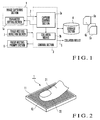
- Fig. 1 shows the arrangement of an image capturing apparatus according to an embodiment of the present invention.
- This embodiment exemplifies a case where the image capturing apparatus is applied to fingerprint collation and will be described as a fingerprint collation apparatus hereinafter.
- This fingerprint collation apparatus includes an image capturing section 1 for converting a fingerprint ridge/valley image into image data which is an electrical signal and outputting it.
- the image capturing section 1 determines a state of conversion to image data in accordance with the parameter set in a parameter setting section 1a.
- the apparatus shown in Fig. 1 also includes a storage section 4 storing registered image data G 1 to G N for fingerprint collation, a finger resting prompt section 6 for prompting a user intending to perform collation to rest his/her finger on the image capturing section 1, a finger resting detection section 7 for detecting that the finger is rested on the image capturing section 1, and a control section 3 for controlling the overall apparatus.
- the control section 3 includes a capture control section 3a formed by a CPU for performing predetermined computation processing in accordance with a program.
- the capture control section 3a determines the image data output from the image capturing section 1 first, and then changes the parameter in the parameter setting section 1a.
- the control section 3 also includes a collation means 3b for collating image data 2 captured by the image capturing section 1 with the registered image data G 1 to G N stored in the storage section 4 and outputting the resultant data as a collation result 5.
- These capture control section 3a and collation means 3b are implemented by programs.
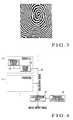
- Fig. 2 shows the arrangement of the image capturing section 1.
- Many sensor cells 11 are vertically and horizontally arranged on a detection surface 12 of the image capturing section 1 in the form of a matrix.
- the sensor cells 11 are formed by elements for converting a fine ridge/valley pattern of a target into an electrical quantity.
- the respective sensor cells 11 detect a ridge/valley pattern of a fingerprint 22.
- one image data 2 representing a fingerprint image like the one shown in Fig. 3 is output from the image capturing section 1.
- Fig. 4 shows the arrangement of the image capturing section 1.
- Each sensor cell 11 is comprised of a detection element 11a and sensor circuit 11b.
- the detection element 11a is, for example, a capacitive sensor formed by an electrode having an insulating layer formed on its surface.
- the detection element 11a may be an optical sensor formed by a photodiode or the like.
- the detection element 11a converts a fingerprint ridge/valley pattern into an electrical signal.
- the sensor circuit 11b then amplifies the converted signal.
- the output of the sensor circuit 11b of each sensor cell 11 is connected to a common data line 13.
- the sensor cells 11 are sequentially selected to output an analog signal corresponding to a fingerprint ridge/valley pattern to the data line 13.
- An A/D conversion circuit 14 sequentially converts the analog signals transmitted through the data line 13 into, for example, 256-level grayscale digital signals in accordance with the parameter set in the parameter setting section 1a, and outputs the signals.
- the digital signals from all the sensor cells 11 are arranged in the form of a matrix so as to reflect the positions of the respective sensor cells, fingerprint image data like that shown in Fig. 3 is obtained.
- the A/D conversion circuit 14 is designed to convert an analog signal corresponding to a fingerprint ridge/valley pattern into a digital signal.
- the relationship between the analog value and the digital value changes in accordance with the parameter value set in the parameter setting section 1a.
- Fig. 5 exemplifies the parameters set in the A/D conversion circuit 14 (Fig. 4).
- Parameters A and B are rational numbers equal to or larger than 0. If the analog value input to the A/D conversion circuit 14 has a level less than a set parameter value (A + B), 0-level grayscale fingerprint image data is obtained from the A/D conversion circuit 14.
- the 0-level grayscale fingerprint image data represents a black image.
- 255-level grayscale fingerprint image data is obtained from the A/D conversion circuit 14.
- the 255-level grayscale fingerprint image data represents a white image. If the analog value input to the A/D conversion circuit 14 is equal to or larger than a parameter value (A + n x B) and less than a parameter value ⁇ A + (n + 1) x B ⁇ , n-level grayscale image data is obtained from the A/D conversion circuit 14.
- the parameter value A As described above, if the parameter value A is set to be large, the fingerprint image obtained from the A/D conversion circuit 14 becomes black. If the parameter value A is set to be small, the fingerprint image obtained from the A/D conversion circuit 14 becomes white. If the parameter value B is set to be large, the fingerprint image obtained from the A/D conversion circuit 14 decreases in resolution. If the parameter value B is set to be small, the fingerprint image obtained from the A/D conversion circuit 14 increases in resolution. Note that the number of grayscale levels is not limited to 256 and may be 64 or 128.
- parameter values A and B are used as parameters set in the parameter setting section 1a to be used for conversion in the image capturing section 1.
- the present invention is not limited to them.
- brightness and resolution can be controlled in the same manner even by using the minimum and maximum values of a signal conversion range as the parameter values A and B, respectively.
- the brightness and resolution of the fingerprint image obtained from the A/D conversion circuit 14 can be changed. If, therefore, the fingerprint images of human fingertips, which change their states depending on individual differences, e.g., dry fingers and fatty fingers, seasons, and physical conditions, accurate fingerprint images free from the influences of individual differences and state changes can be acquired by capturing images upon setting appropriate parameter values.
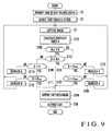
- the capture control section 3a of the control section 3 causes the finger resting prompt section 6 to prompt the user intending to perform collation to rest his/her finger on the detection surface 12 (Fig. 2) of the image capturing section 1 (step S1). More specifically, for example, the finger resting prompt section 6 prompts the user to rest his/her finger by displaying a prompt using a display unit such as an LED or light-emitting element, turning on a predetermined indication, or outputting a voice message.
- the image capturing section 1 captures a fingerprint image and outputs the image data 2 (step S3).
- the capture control section 3a calculates a grayscale index Y, as an image quality evaluation, which indicates the density of the captured image (step S4).
- a grayscale index Y is any kind of index as long as it indicates the density balance of image data to be evaluated.
- the ratio of the number of pixels with grayscale values equal to or less than a predetermined grayscale value to the total number of pixels of image data may be used as an index.
- an index may be calculated by using a predetermined area, e.g., an area near the center of the detection surface 12, as a target area instead of using the total number of pixels.
- a grayscale index can be calculated within a short period of time as compared with the case where the total number of pixels are targeted.
- the capture control section 3a compares the grayscale index Y obtained in the above manner with preset threshold Y th1 and Y th2 .
- step S5 the capture control section 3a checks whether the calculated grayscale index Y is equal to or more than the threshold Y th1 . If it is determined in step S5 that the grayscale index Y is equal to or more than the threshold Y th1 , the flow advances to step S6 to check whether the grayscale index Y is equal to or less than the threshold Y th2 . If it is determined in step S6 that the grayscale index Y is equal to or less than the threshold Y th2 , the flow advances to step S7, in which the capture control section 3a outputs the captured image data to the collation means 3b.
- step S5 If it is determined in step S5 that the grayscale index Y is less than the threshold Y th1 , the flow advances to step S8 to check whether the parameter B set in the parameter setting section 1a is the maximum value.
- step S8 If it is determined in step S8 that the set parameter B is not the maximum value, the flow advances to step S9, in which the capture control section 3a increases the parameter B in the parameter setting section 1a by a predetermined value. The flow then returns to step S3. If it is determined in step S8 that the parameter B set in the parameter setting section 1a is the maximum value, the flow advances to step S10 to check whether the parameter A set in the parameter setting section 1a is the maximum value.
- step S10 If it is determined in step S10 that the set parameter A is not the maximum value, the flow advances to step S11, in which the capture control section 3a increases the parameter A in the parameter setting section 1a by a predetermined value. The flow then returns to step S3. If it is determined in step S10 that the parameter is the maximum value, the flow advances to step S7, in which the capture control section 3a outputs the captured image data to the collation means 3b.
- step S6 If it is determined in step S6 that the grayscale index Y exceeds the threshold Y th2 , the flow advances to step S12 to check whether the parameter value A set in the parameter setting section 1a is the minimum value, e.g., 0.
- step S13 the flow advances to step S13 to decrease the parameter value A in the parameter setting section 1a by a predetermined value. The flow then returns to step S3. If it is determined in step S12 that the parameter value A set in the parameter setting section 1a is 0, the flow advances to step S14 to check whether the parameter value B set in the parameter setting section 1a is the minimum value.
- step S14 If it is determined in step S14 that the set parameter value B is not the minimum value, the flow advances to step S15, in which the capture control section 3a decreases the parameter value B in the parameter setting section 1a by a predetermined value. The flow then returns to step S3. If it is determined in step S14 that the parameter value B is the minimum value, the flow advances to step S7, in which the capture control section 3a outputs the captured image data to the collation means 3b.
- the capture control section 3a repeats the above series of operations until the image quality of image data satisfies a predetermined condition. When the condition is satisfied, the capture control section 3a outputs the image data as an image suitable for authentication to the collation means 3b. As described above, according to this embodiment, an image in a desired state which falls within the ranges of set parameters can be obtained.
- the collation means 3b which has received the image data, performs authentication processing by comparing the received image data with the registered image data G 1 to G N stored in the storage section 4.
- a grayscale index is used as an image quality evaluation index for captured image data.
- the present invention is not limited to this.
- saturation, lightness, contrast, or the like may be used as an index.
- a spatial frequency component extracted from captured image data by a Fourier transform may be used as an index.
- whether the response of a fingerprint is properly acquired as an image can be evaluated.
- an image may be evaluated in combination with a grayscale index.
- a grayscale index is used as an image quality evaluation index.
- the ridges of fingerprint patterns differ in thickness and intervals among target persons. For this reason, image data determined as data having optimal image quality on the basis of a grayscale index may not be image data having optimal image quality for authentication.
- a histogram index is used for evaluation of image quality to solve the above problem. Note that the ridges are lines forming a pattern obtained from the ridge portions of a fingertip skin surface.
- a histogram index from which a histogram representing the grayscale of an image represented by captured image data is generated can be calculated from the captured image data.
- the abscissa represents the grayscale value; and the ordinate, the frequency.
- Grayscale values represent the densities between black and white in 256 levels (grayscale levels).
- Grayscale level 0 represents black, and grayscale level 255 represents white.
- a histogram index like that shown in Fig. 7B is calculated from captured image data like that shown in Fig. 7A.
- a histogram index like that shown in Fig. 7D is calculated from captured image data like that shown in Fig. 7C.
- Fig. 8A when image data is captured as shown in Fig. 8A, two peak portions representing the density of a ridge and noise or the like appear in a histogram as shown in Fig. 8B.
- a calibration circuit is provided for an image capturing section 1 (Fig. 1) to suppress/reduce noise and the like, only one peak portion representing the density of a ridge can be made to appear in a histogram, as shown in Figs. 7B and 7D.
- the frequency which is located on the small grayscale value side indicated by the histogram index and exhibits the maximum value on the high density side is regarded as a peak value
- the frequency which corresponds to the minimum value immediately near the peak value on the lower density side than that of the peak value is regarded as a tail value.
- the tail value exists on the right side of the peak value in the histogram shown in Fig. 7.
- the minimum value between the two peak portions becomes a tail value
- the maximum value of the peak portion on the left of the tail value represents the peak value.
- parameters A and B are set on the basis of this histogram index H.
- the values of the parameters A and B are set to increase the histogram index H so as to obtain a result like that shown in Fig. 7D. With this operation, the contrast of the fingerprint image increases as shown in Fig. 7C, thereby obtaining a clear fingerprint image.
- a preset reference value range i.e., an appropriate range
- the capture control section 3a of a control section 3 causes the finger resting prompt section 6 to prompt a user intending to perform collation to rest his/her finger on the detection surface 12 (Fig. 2) of the image capturing section 1 (step S1). More specifically, for example, the finger resting prompt section 6 prompts the user to rest his/her finger by displaying a prompt using a display unit such as an LED or light-emitting element, turning on a predetermined indication, or outputting a voice message.
- the image capturing section 1 captures a fingerprint image and outputs image data 2 (step S3).
- the capture control section 3a calculates the histogram index H as an image quality evaluation index for the captured image from the image data 2 (step S101).
- the histogram index H may be calculated from a predetermined area of the captured image, e.g., an area near the center of the detection surface 12, instead of all the pixels of the captured image. In this case, the histogram index H can be calculated within a short period of time as compared with the case where all the pixels are targeted.
- the capture control section 3a compares the histogram index H obtained in the above manner with preset thresholds H th1 and H th2 .
- step S102 the capture control section 3a checks whether the calculated histogram index H is equal to or more than the threshold H th1 . If it is determined in step S102 that the histogram index H is equal to or more than the threshold H th1 , the flow advances to step S103 to check whether the histogram index H is equal to or less than the threshold H th2 . If it is determined in step S103 that the histogram index H is equal to or less than the threshold H th2 , the flow advances to step S104, in which the capture control section 3a outputs the captured image data to a collation means 3b.
- step S102 If it is determined in step S102 that the histogram index H is less than the threshold H th1 , the flow advances to step S105 to check whether the parameter value B set in the parameter setting section 1a is the maximum value.
- step S105 If it is determined in step S105 that the set parameter value B is not the maximum value, the flow advances to step S106, in which the capture control section 3a increases the parameter value B in the parameter setting section 1a by a predetermined value. The flow then returns to step S3. If it is determined in step S105 that the parameter value B set in the parameter setting section 1a is the maximum value, the flow advances to step S107 to check whether the parameter value A set in the parameter setting section 1a is the maximum value.
- step S107 If it is determined in step S107 that the set parameter value A is not the maximum value, the flow advances to step S108, in which the capture control section 3a increases the parameter value A in the parameter setting section 1a by a predetermined value. The flow then returns to step S3. If it is determined in step S107 that the parameter value A is the maximum value, the flow advances to step S104, in which the capture control section 3a outputs the captured image data to the collation means 3b.
- step S103 If it is determined in step S103 that the histogram index H exceeds the threshold H th2 , the flow advances to step S109 to check whether the parameter value A set in the parameter setting section 1a is the minimum value, e.g., 0.
- step S110 the capture control section 3a decreases the parameter value A in the parameter setting section 1a by a predetermined value. The flow then returns to step S3. If it is determined in step S109 that the parameter value A set in the parameter setting section 1a is 0, the flow advances to step S111 to check whether the parameter value B set in the parameter setting section 1a is the minimum value.
- step S111 If it is determined in step S111 that the set parameter value B is not the minimum value, the flow advances to step S112, in which the capture control section 3a decreases the parameter value B in the parameter setting section 1a by a predetermined value. The flow then returns to step S3. If it is determined in step S111 that the parameter value B is the minimum value, the flow advances to step S104, in which the capture control section 3a outputs the captured image data to the collation means 3b.
- the capture control section 3a repeats the above series of operations until the image quality of image data satisfies a predetermined condition. When the condition is satisfied, the capture control section 3a outputs the image data as an image suitable for authentication to the collation means 3b.
- a fingerprint image with excellent contrast can be acquired without being influenced by the density of a fingerprint pattern and individual differences.
- the collation means 3b which has received the image data, performs authentication processing by comparing the received image data with registered image data G 1 to G N stored in the storage section 4.
- the above operation may be performed after the histogram of the captured fingerprint image is smoothed. This makes it possible to reduce the influence of fluctuations in histogram due to noise, variations, or the like.
- Fig. 10 shows the arrangement of the image capturing section 1 having a calibration circuit 105. Note that since many sensor cells have the same arrangement, Fig. 10 representatively shows one sensor cell.
- the sensor cell 11 is comprised of the detection element 11a, sensor circuit 11b, and output signal level correction circuit 101.
- the output signal level correction circuit 101 receives an output from the sensor circuit 11b and supplies the output from the sensor circuit 11b to one of the inputs of a comparing circuit 104.
- the comparing circuit 104 compares the output from the sensor circuit 11b with the calibration reference value (signal) output from a calibration reference signal generating circuit 103.
- the calibration circuit 105 adjusts (corrects) the output level of the sensor circuit 11b by performing gain control on the input side of the sensor circuit 11b or the sensor circuit 11b so as to eliminate the difference between the above two values, which is output from the comparing circuit 104.
- the calibration reference signal generating circuit 103 is preferably configured to generate calibration reference signals at the same level to the respective sensor cells.
- any known arrangement that has the function of minimizing variations in outputs from the respective sensor cells 11 and operates in the above manner can be used as the output signal level correction circuit 101.
- the outputs of the respective sensor circuits i.e., the output levels of the respective sensor cells 11, can be adjusted to the same level, thus suppressing noise due to sensitivity variations and eliminating a peak portion due to noise from a histogram index like that shown in Fig. 8B.
- Fig. 11 shows the arrangement of part of the image capturing section 1 formed by the sensor cells 11 each having the calibration circuit 105.
- Each sensor cell 11 has the same arrangement and is comprised of the detection element 11a, sensor circuit 11b, and calibration circuit (sensitivity adjusting circuit) 105. The detection sensitivity of each sensor cell 11 is adjusted by using the calibration circuit 105.
- Each sensor cell includes the calibration circuit 105, a signal processing circuit 110, and a control line L C .
- the sensor cell 11 is comprised of the detection element 11a, sensor circuit 11b, and calibration circuit 105.
- the detection element 11a is an element for converting a surface shape into an electrical signal.
- the sensor circuit 11b is a circuit for measuring an electrical quantity in the detection element 11a which changes depending on the surface shape.
- each sensor cell 11 When the output level of each sensor cell 11 is to be corrected, i.e., calibration is to be performed, a reference sample without any uneven pattern is detected as a measurement target by the sensor cell 11 or detection is performed without any object placed on the sensor cell, thereby making each sensor cell 11 detect the same measurement value.
- the signal output from the sensor cell 11 is input to an A/D conversion circuit 14 through a data line L D and output as a digital output signal 4A.
- the digital output signal 4A output from the A/D conversion circuit 14 is input to the signal processing circuit 110.
- the signal processing circuit 110 compares the digital output signal 4A output form the A/D conversion circuit 14 with the digital output signal which should be output (to be referred to as an expected value hereinafter) to calculate an adjustment parameter for adjusting the detection sensitivity of the sensor circuit 11b.
- the calibration circuit 105 is then controlled through the control line L C on the basis of the calculated adjustment parameter.
- the data line L D and control line L C are common to the respective sensor cells 11.
- the sensor cells 11 are sequentially selected, and output signals 2A from the sensor cells 11 are sequentially input to the A/D conversion circuit 14.
- the signal processing circuit 110 controls the calibration circuit 105 in the sensor cell 11.
- each sensor circuit 11b The sensitivity of each sensor circuit 11b is adjusted by repeating this operation once or more for each sensor cell, thereby making the performance of each sensor cell 11 uniform.
- the signal processing circuit 110 includes the comparing circuit 104 and calibration reference signal generating circuit 103 described with reference to Fig. 10.
- the input signal is a digital signal.
- a digital signal is input to the comparing circuit 104 without any conversion, a known digital comparing circuit can be used as the comparing circuit 104. If the comparing circuit 104 is a general analog comparing circuit, an input signal is D/A-converted first and then supplied to the comparing circuit 104. The same applies to the calibration reference signal generating circuit 103.
- the image capturing section 1 may be formed by sensor cells 11 each havingthe calibration circuit 105.
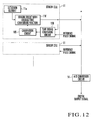
- the image capturing section 1 shown in Fig. 12 uses a sensor circuit 11b' with a voltage/time conversion function and a time signal comparing circuit 106.
- the sensor circuit 11b' with the voltage/time conversion function is a sensor circuit for converting an output signal corresponding to an electrical quantity from the detection element 11a into a signal that changes along the time axis.
- the time signal comparing circuit 106 compares the voltage/time conversion signal output from the sensor circuit 11b' with the voltage/time conversion function with a calibration reference signal, and outputs the signal difference as a control signal to the calibration circuit 105.
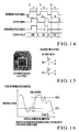
- the sensor circuit 11b' with the voltage/time conversion function converts a signal having analog information as a voltage value into a signal having analog information in the time axis direction, and outputs the resultant signal as an output signal 2B like that shown in Fig. 14 (see Fig. 14: t s is output time and changes).
- the output signal 2B is input to the A/D conversion circuit 14 through the data line L D and output as a digital output signal.
- the output signal 2B is supplied to the calibration circuit 105 through the time signal comparing circuit 106 in the sensor cell 11.
- the time signal comparing circuit 106 corresponds to the comparing circuit 102 in Fig. 10 and obtains the time difference between the output signal 2B from the sensor circuit 11b' with the voltage/time conversion function and a reference pulse signal having a reference time t R from the calibration reference signal generating circuit.
- the time signal comparing circuit 106 compares the signal voltage/time-converted by the sensor circuit 11b' with the voltage/time conversion function with the reference pulse signal, and sends a comparison pulse signal representing the time difference between them to the calibration circuit 105. With this operation, the calibration circuit 105 performs control operation to eliminate the time difference from the output from the sensor circuit 11b' with the voltage/time conversion function.
- the data line L D is shared by the plurality of sensor cells 11. The sensor cells 11 are sequentially selected, and the above operation is performed.
- Fig. 13 shows an example of the arrangement of each sensor circuit with the voltage/time conversion function.
- the sensor circuit 11b' with the voltage/time conversion function has, for example, a voltage/time conversion circuit 121.
- a voltage/time conversion circuit 121 a general-purpose circuit or the like may be used.
- this circuit may be comprised of a constant current circuit, capacitive element, and threshold circuit 121a (see, for example, Japanese Patent Application No. 11-157755).
- the time signal comparing circuit 106 is typically formed by an AND circuit.
- the time signal comparing circuit 106 ANDs the output signal 2B from the sensor circuit 11b' with the voltage/time conversion function and the reference pulse signal from the reference pulse signal generating circuit (not shown), and outputs the resultant data as a comparison signal to a counter circuit 154.
- the value of the counter circuit 154 is set in advance to an initial set value that controls all load elements Z 1 to Z N constituting a load circuit 151 in an inactive state, and the output signal 2B from the sensor circuit 11b' with the voltage/time conversion function is also set in advance to an initial set value. If the output signal 2B changes earlier than a predetermined time in the first sense operation (for example, sense operation is performed without placing any object such as a finger 21 on the detection surface 12 of the image capturing section 1 and an output signal from the sensor cell changes within a sense time), the counter circuit 154 is counted up by one on the basis of the output from the time signal comparing circuit 106. As a result, the data in the counter circuit 154 changes to activate one of the load elements Z 1 to Z N . In addition, the output signal 2B from the sensor circuit 11b' with the voltage/time conversion function is also restored to the initial set value in advance.
- the counter circuit 154 is further counted up by one. In this case, if the values of the load elements Z 1 to Z N are set to be sequentially doubled in accordance with the bits of the counter, twice as many load elements are activated as a consequence.
- This operation is repeated until the output signal from the sensor circuit 11b' with the voltage/time conversion function does not change in the predetermined time (for example, sense operation is performed without placing the finger 13, and the output signal from the sensor cell does not change in the sense time).
- the counter circuit 154 is ceased to be counted up, and no load element is connected to the sensor circuit 11b' with the voltage/time conversion function any more.
- the power consumption of the overall apparatus can be reduced as compared with other embodiments.
- a ridge count index is used as an image quality evaluation index.
- a ridge count index will be described first with reference to Fig. 15.
- a ridge of a fingerprint appears as a low-grayscale (black) line in a fingerprint image.
- a ridge count index N is obtained in the following manner. First, average ridge counts of a fingerprint in the horizontal and vertical directions are counted within the fingerprint determination area (n x m pixels) shown in Fig. 15. A larger one of the average ridge counts is then selected as the ridge count index N.
- an average ridge count Nv in the horizontal direction per a pixel count P is calculated by multiplying mathematical expression (1) by P/m so as to normalize the above average ridge count into a determined count per P pixels according to equation (2):
- Fig. 16 explains a ridge determination condition.
- the ordinate represents the grayscale value of each pixel; and the abscissa, the pixels in the vertical or horizontal direction in the determination area.
- ridges can be counted after the grayscale value of a fingerprint image is smoothed. This makes it possible to reduce the influences of fluctuations in the fingerprint image due to noise, apparatus variations, and the like.
- the ridge count index N takes an extremely small value, it indicates a state where the fingerprint image has collapsed. If the ridge count index N takes a large value, it indicates a state where the fingerprint image has faded and ridges have broken. If, therefore, the ridge count index N takes an extremely small value, parameters A and B are adjusted to decrease the image density so as to prevent the image from collapsing. If the ridge count index N takes an extremely large value, the parameters A and B are adjusted to increase the image density. With this operation, an appropriate fingerprint image free from the influences of the density of a fingerprint pattern can be acquired.
- an ridge count index can also be calculated from valleys (the white lines in the fingerprint image in Fig. 15) instead of the ridges (the black lines in the fingerprint image in Fig. 15).
- an evaluation index equivalent to a ridge count index can be obtained.
- Valleys can be counted as follows. Referring to Fig. 16, for example, when the curve crosses the two thresholds LVTH and HVTH in the order named, one valley can be counted. In this case, one threshold can also be set.
- the apparatus according to this embodiment has the same arrangement as that of the image capturing apparatus (fingerprint collation apparatus) according to each of the other embodiments described above.
- a capture control section 3a operates as shown in Fig. 17. The operation of the capture control section 3a in the fingerprint collation apparatus according to this embodiment will be described below. Note that a description of constituent elements equivalent to those in Fig. 9 will be omitted as needed.
- the finger resting prompt section 6 prompts the user intending to perform collation to rest his/her finger on the detection surface 12 (Fig. 2) of theimage capturing section 1 (step S1). More specifically, for example, the finger resting prompt section 6 prompts the user to rest his/her finger by displaying a prompt using a display unit such as an LED or light-emitting element, turning on a predetermined indication, or outputting a voice message.
- the finger resting detection section 7 detects that the user rests his/her finger on the detection surface 12 upon prompting (step S2)
- the image capturing section 1 captures a fingerprint image and outputs image data 2 (step S3).
- the capture control section 3a calculates the ridge count index N of the captured image as an image quality evaluation index for the image data 2 (step S201).
- the ridge count index N may be calculated from a predetermined area of the captured image, e.g., an area near the center of the detection surface 12, instead of all the pixels of the captured image. In this case, the ridge count index N can be calculated in a short period of time as compared with the case where all the pixels are targeted.
- the capture control section 3a compares the ridge count index N obtained in the above manner with preset thresholds N th1 and N th2 .
- step S202 determines in step S202 that the calculated ridge count index N is equal to or less than N th2 . If the capture control section 3a determines in step S202 that the calculated ridge count index N is equal to or less than N th2 , the flow advances to step S203 to check whether the ridge count index N is equal to or larger than N th1 . If it is determined in step S203 that the ridge count index N is equal to or more than the threshold N th1 , the flow advances to step S204, in which the capture control section 3a outputs the captured image data to the collation means 3b.
- step S205 If it is determined in step S205 that the set parameter value B is not the maximum value, the flow advances to step S206, in which the capture control section 3a increases the parameter value B in the parameter setting section 1a by a predetermined value. The flow then returns to step S3. If it is determined in step S205 that the parameter value B set in the parameter setting section 1a is the maximum value, the flow advances to step S207 to check whether the parameter value A set in the parameter setting section 1a is the maximum value.
- step S207 If it is determined in step S207 that the set parameter value A is not the maximum value, the flow advances to step S208, in which the capture control section 3a increases the parameter value A in the parameter setting section 1a by a predetermined value. The flow then returns to step S3. If it is determined in step S207 that the parameter value A is the maximum value, the flow advances to step S204, in which the capture control section 3a outputs the captured image data to the collation means 3b.
- step S203 If it is determined in step S203 that the ridge count index N is less than the threshold N th1 , the flow advances to step S209 to check whether the parameter value A set in the parameter setting section 1a is the minimum value, e.g., 0.
- step S211 If it is determined in step S211 that the set parameter value B is not the minimum value, the flow advances to step S212, in which the capture control section 3a decreases the parameter value B in the parameter setting section 1a by a predetermined value. The flow then returns to step S3. If it is determined in step S211 that the parameter value B is the minimum value, the flow advances to step S204, in which the capture control section 3a outputs the captured image data to the collation means 3b.
- the capture control section 3a repeats the above series of operations until the image quality of the image data satisfies a predetermined condition. When the condition is satisfied, the capture control section 3a outputs the image data as an image suitable for authentication to the collation means 3b.
- a fingerprint image free from collapse or fading can be acquired without being influenced by the density of a fingerprint pattern, individual differences, and state changes.
- the location and size of a fingerprint determination area can be arbitrarily set, as needed.
- a combination of a histogram index and a ridge count index is used as an evaluation index in an image processing apparatus and fingerprint collation apparatus.
- a new index may be obtained from a histogram index and ridge count index by a predetermined computation, and the parameters A and B may be changed on the basis of this index.
- the present invention can be applied upon replacement of the ridge count index with the ridge count index calculated by using valleys as described in the second embodiment.
- analog values are converted into digital values with 256 grayscale levels.
- values may be converted into values other than values with 256 grayscale levels.
- the parameter values A and B are used as parameters to be set in the parameter setting section 1a and used for conversion in the image capturing section 1.
- the present invention is not limited to them.
- the minimum and maximum values of a signal conversion range may be used as the parameter values A and B.
- the number of parameters to be set is not limited to this, and can be arbitrarily changed, as needed.
- the above embodiments have exemplified the combination of a grayscale index indicating the density of image data and an index indicting the spatial frequency component of an image and the combination of a histogram index generated from a histogram representing the density of an image and a ridge count index generated on the basis of the number of ridges in the image.
- the present invention is not limited to them.
- a new evaluation index may be generated by combining the respective evaluation indexes, as needed.
- image data is captured such that evaluation indexes for an image as, for example, a fingerprint collation target, fall within certain ranges. This produces an excellent effect. That is, an image in a desired state can be obtained. For example, the precision of fingerprint collation can be improved.
Landscapes
- Engineering & Computer Science (AREA)
- General Physics & Mathematics (AREA)
- Human Computer Interaction (AREA)
- Physics & Mathematics (AREA)
- Multimedia (AREA)
- Theoretical Computer Science (AREA)
- Vascular Medicine (AREA)
- General Health & Medical Sciences (AREA)
- Health & Medical Sciences (AREA)
- Image Input (AREA)
- Collating Specific Patterns (AREA)
- Measurement Of The Respiration, Hearing Ability, Form, And Blood Characteristics Of Living Organisms (AREA)
- Image Analysis (AREA)
Abstract
Description



Claims (26)
- An image capturing apparatus characterized by comprising:an image capturing section (1) for converting a shape of an object into an electrical quantity in accordance with a parameter value set in a parameter setting section (1a), and outputting image data representing an image corresponding to the shape of the object; anda capture control section (3a) for receiving the image data output from said image capturing section, calculating an evaluation index for evaluating image quality of the image from the image data, and if the evaluation index falls outside a range of a preset reference value, changing the parameter value set in said parameter setting section so as to make the evaluation index fall within the range of the reference value to output image data which is received from said image capturing section and the evaluation index of which falls within the range of the reference value.
- A fingerprint collation apparatus
characterized by comprising:an image capturing section (1) for converting a fingerprint ridge/valley pattern into an electrical quantity in accordance with a parameter value set in a parameter setting section (1a), and outputting image data representing a fingerprint image corresponding to the fingerprint ridge/valley pattern;a capture control section (3a) for receiving the image data output from said image capturing section, calculating an evaluation index for evaluating image quality of the fingerprint ridge/valley pattern image from the image data, and if the evaluation index falls outside a range of a preset reference value, changing the parameter value set in said parameter setting section so as to make the evaluation index fall within the range of the reference value to output image data which is received from said image capturing section and the evaluation index of which falls within the range of the reference value; andcollation means for comparing and collating image data output from said capture control section with registered image data prepared in advance. - An apparatus according to claim 1 or 2, wherein when the parameter value set in said parameter setting section is changed, said image capturing section outputs image data obtained by performing conversion again in accordance with the changed parameter value.
- An apparatus according to claim 1, wherein said image capturing section comprises:a detection element (11a) for converting the shape of the object into an analog signal; andan A/D conversion circuit (14) for converting the analog signal output from said detection element into a digital signal in accordance with the parameter value set in said parameter setting section and outputting the signal as the image data, andthe parameter value set in said parameter setting section includes a conversion range and conversion resolution in converting the analog signal into the digital signal.
- An apparatus according to claim 2 , wherein said image capturing section comprises:a detection element (11a) for converting the fingerprint ridge/valley pattern into an analog signal; andan A/D conversion circuit (14) for converting the analog signal output from said detection element into a digital signal in accordance with the parameter value set in said parameter setting section and outputting the signal as the image data, andthe parameter value set in said parameter setting section includes a conversion range and conversion resolution in converting the analog signal into the digital signal.
- An apparatus according to claim 1 or 2, wherein the evaluation index calculated by said capture control section is a grayscale index indicating a density of the image data output from said image capturing section.
- An apparatus according to claim 1 or 2, wherein the evaluation index calculated by said capture control section is an index indicating a spatial frequency component of the image data output from said image capturing section.
- An apparatus according to claim 1 or 2, wherein the evaluation index calculated by said capture control section is a combination of a grayscale index indicating a density of the image data output from said image capturing section and an index indicating a spatial frequency component of the image output from said image capturing section.
- An apparatus according to claim 1 or 2, wherein the evaluation index calculated by said capture control section is a histogram index generated from a histogram representing a density of the image.
- An apparatus according to claim 1 or 2, wherein the evaluation index calculated by said capture control section is a ridge count index generated on the basis of the number of ridges in the image.
- An apparatus according to claim 1 or 2, wherein the evaluation index calculated by said capture control section is a combination of a histogram index generated from a histogram representing a density of the image and a ridge count index generated on the basis of the number of ridges in the image.
- An apparatus according to claim 9,wherein said capture control section calculates, as the histogram index, a ratio between a maximum value on a side of the histogram where a density of the image is high and a minimum value immediately near the maximum value on a side where the density of the image is lower than the density representing the maximum value.
- An apparatus according to claim 10, wherein said capture control section obtains an average ridge count in the horizontal direction which is an average ridge count per unit length of the image in the horizontal direction and an average ridge count in the vertical direction which is an average ridge count per unit length of the image in the vertical direction, and calculates a larger one of the average ridge count in the horizontal direction and the average ridge count in the vertical direction as the ridge count index.
- An image capturing method characterized by comprising:converting a shape of an object into an electrical quantity in accordance with a preset parameter value to generate image data representing an image corresponding to the shape of the object;calculating an evaluation index for evaluating image quality of the image from the image data; andchanging the parameter value to make the evaluation index fall within a range of a preset reference value.
- A fingerprint collation method characterized by comprising:converting a fingerprint ridge/valley pattern into an electrical quantity in accordance with a preset parameter value to generate image data representing a fingerprint image corresponding to the fingerprint ridge/valley pattern;calculating an evaluation index for evaluating image quality of the image from the image data;changing the parameter value to make the evaluation index fall within a range of a preset reference value; andcomparing and collating the image data whose evaluation index falls within the range of the reference value with registered image data prepared in advance.
- A method according to claim 14, whereinthe parameter value includes a conversion range and conversion resolution in converting an analog signal into a digital signal,the shape of the object is converted into an analog signal, andthe analog signal is converted into a digital signal in accordance with the parameter value and output as the image data.
- A method according to claim 15, whereinthe parameter value includes a conversion range and conversion resolution in converting an analog signal into a digital signal,the fingerprint ridge/valley pattern is converted into an analog signal, andthe analog signal is converted into a digital signal in accordance with the parameter value and output as the image data.
- A method according to claim 14 or 15, wherein the evaluation index is a grayscale index indicating a density of the image data.
- A method according to claim 14 or 15, wherein the evaluation index is an index indicating a spatial frequency component of the image data.
- A method according to claim 14 or 15, wherein the evaluation index is a combination of a grayscale index indicating a density of the image data and an index indicating a spatial frequency component of the image data.
- A method according to claim 14 or 15, wherein the evaluation index is a histogram index generated from a histogram representing a density of the image.
- A method according to claim 14 or 15, wherein the evaluation index is a ridge count index generated on the basis of the number of ridges in the image.
- A method according to claim 14 or 15, wherein the evaluation index is a combination of a histogram index generated from a histogram representing a density of the image and a ridge count index generated on the basis of the number of ridges in the image.
- A method according to claim 21, wherein the histogram index is a ratio between a maximum value on a side of the histogram where a density of the image is high and a minimum value immediately near the maximum value on a side where the density of the image is lower than the density representing the maximum value.
- A method according to claim 22, wherein the ridge count index is a larger one of an average ridge count per unit length of the image in the horizontal direction and an average ridge count per unit length of the image in the vertical direction.
- An apparatus according to claim 2 , whereinsaid apparatus further comprises a finger resting detection section for detecting that a finger is rested on said image capturing section, andwhen said finger resting detection section detects that the finger is rested on said image capturing section, said image capturing section converts a fingerprint ridge/valley pattern into an electrical amount in accordance with a parameter set in said parameter setting section, and outputting image data representing a fingerprint image corresponding to the fingerprint ridge/valley pattern.
Applications Claiming Priority (4)
| Application Number | Priority Date | Filing Date | Title |
|---|---|---|---|
| JP2000381740 | 2000-12-15 | ||
| JP2000381740 | 2000-12-15 | ||
| JP2001274858 | 2001-09-11 | ||
| JP2001274858 | 2001-09-11 |
Publications (3)
| Publication Number | Publication Date |
|---|---|
| EP1215620A2 true EP1215620A2 (en) | 2002-06-19 |
| EP1215620A3 EP1215620A3 (en) | 2004-12-22 |
| EP1215620B1 EP1215620B1 (en) | 2007-07-25 |
Family
ID=26605895
Family Applications (1)
| Application Number | Title | Priority Date | Filing Date |
|---|---|---|---|
| EP01250441A Expired - Lifetime EP1215620B1 (en) | 2000-12-15 | 2001-12-14 | Image capturing method and apparatus and fingerprint collation method and apparatus |
Country Status (3)
| Country | Link |
|---|---|
| US (1) | US6990219B2 (en) |
| EP (1) | EP1215620B1 (en) |
| DE (1) | DE60129526T2 (en) |
Cited By (6)
| Publication number | Priority date | Publication date | Assignee | Title |
|---|---|---|---|---|
| DE10356147A1 (en) * | 2003-12-02 | 2005-06-30 | Giesecke & Devrient Gmbh | Digitization of a papillary structure |
| WO2005076195A1 (en) * | 2004-02-04 | 2005-08-18 | Julian Mark Douglas Ashbourn | Automatic performance calibration (apc) |
| EP1585055A3 (en) * | 2004-03-31 | 2006-11-02 | Seiko Epson Corporation | A method of focusing a fingerprint image and a fingerprint sensing device |
| CN106056081A (en) * | 2016-05-30 | 2016-10-26 | 广东欧珀移动通信有限公司 | Unlocking control method and terminal equipment |
| EP3249578A1 (en) * | 2016-05-27 | 2017-11-29 | Guangdong Oppo Mobile Telecommunications Corp., Ltd. | Fingerprint unlocking method and terminal |
| EP3252663A1 (en) * | 2016-05-30 | 2017-12-06 | Guangdong Oppo Mobile Telecommunications Corp., Ltd. | Method for controlling unlocking and terminal |
Families Citing this family (20)
| Publication number | Priority date | Publication date | Assignee | Title |
|---|---|---|---|---|
| US7139427B2 (en) * | 2003-02-07 | 2006-11-21 | Samsung Electronics Co., Ltd. | Method for detecting pattern-like images and method for enhancing images while suppressing undesirable artifacts caused by pattern-like images |
| JP4525286B2 (en) * | 2004-10-14 | 2010-08-18 | 沖電気工業株式会社 | Biometric information authentication apparatus and authentication method |
| JP4501627B2 (en) * | 2004-10-19 | 2010-07-14 | カシオ計算機株式会社 | Image collation device, image collation method, and image collation program |
| US7936907B2 (en) | 2006-04-26 | 2011-05-03 | Aware, Inc. | Fingerprint preview quality and segmentation |
| US7831083B1 (en) * | 2006-07-13 | 2010-11-09 | Kla-Tencor Technologies Corporation | Image quality monitoring for substrate inspection |
| US8219857B2 (en) * | 2008-06-26 | 2012-07-10 | International Business Machines Corporation | Temperature-profiled device fingerprint generation and authentication from power-up states of static cells |
| CN101739564A (en) * | 2008-11-12 | 2010-06-16 | 深圳富泰宏精密工业有限公司 | System and method for fingerprint identification |
| US8535133B2 (en) * | 2009-11-16 | 2013-09-17 | Broadcom Corporation | Video game with controller sensing player inappropriate activity |
| US9986208B2 (en) * | 2012-01-27 | 2018-05-29 | Qualcomm Incorporated | System and method for determining location of a device using opposing cameras |
| US9342732B2 (en) * | 2012-04-25 | 2016-05-17 | Jack Harper | Artificial intelligence methods for difficult forensic fingerprint collection |
| US20140093145A1 (en) * | 2012-10-02 | 2014-04-03 | Dannie Gerrit Feekes | Algorithms For Hardware-Oriented Biometric Matching |
| US9576176B2 (en) | 2013-07-22 | 2017-02-21 | Apple Inc. | Noise compensation in a biometric sensing device |
| US9727770B2 (en) | 2013-07-22 | 2017-08-08 | Apple Inc. | Controllable signal processing in a biometric device |
| US9552525B2 (en) | 2013-09-08 | 2017-01-24 | Apple Inc. | Noise reduction in biometric images |
| US9939400B1 (en) | 2013-09-09 | 2018-04-10 | Apple Inc. | Fixed pattern noise compensation techniques for capacitive fingerprint sensors |
| CN105913514B (en) * | 2016-04-08 | 2018-03-27 | 广东欧珀移动通信有限公司 | The method and terminal of a kind of unlocked by fingerprint |
| CN106055955B (en) * | 2016-05-30 | 2017-10-24 | 广东欧珀移动通信有限公司 | Unlocking control method and terminal equipment |
| KR102418780B1 (en) * | 2017-09-15 | 2022-07-11 | 삼성디스플레이 주식회사 | Biometric information detecting device and display apparatus having the same |
| TWI679583B (en) * | 2017-10-20 | 2019-12-11 | 映智科技股份有限公司 | Fingerprint detection device and method for improving image quality |
| CN112699766A (en) * | 2020-12-25 | 2021-04-23 | 北京彼岸行舟科技有限公司 | Fingerprint image extraction method |
Family Cites Families (12)
| Publication number | Priority date | Publication date | Assignee | Title |
|---|---|---|---|---|
| EP0404396B1 (en) * | 1989-06-19 | 1994-10-05 | International Business Machines Corporation | Image capture system and method |
| JP2803313B2 (en) | 1990-04-16 | 1998-09-24 | 株式会社デンソー | Fingerprint collation device |
| JP3057590B2 (en) | 1992-08-06 | 2000-06-26 | 中央発條株式会社 | Personal identification device |
| EP0640933A3 (en) | 1993-08-23 | 1995-09-13 | Gim Ges Fuer Innovation Und Ma | Method and device for pattern recognition. |
| US5659626A (en) * | 1994-10-20 | 1997-08-19 | Calspan Corporation | Fingerprint identification system |
| JPH0969152A (en) | 1995-09-01 | 1997-03-11 | Nippon Yunishisu Kk | Surface image acquisition device |
| US6259804B1 (en) * | 1997-05-16 | 2001-07-10 | Authentic, Inc. | Fingerprint sensor with gain control features and associated methods |
| US6330345B1 (en) | 1997-11-17 | 2001-12-11 | Veridicom, Inc. | Automatic adjustment processing for sensor devices |
| US6134340A (en) * | 1997-12-22 | 2000-10-17 | Trw Inc. | Fingerprint feature correlator |
| US6463165B1 (en) * | 1998-03-31 | 2002-10-08 | Mitsubishi Denki Kabushiki Kaisha | Individuals checking apparatus |
| JP2000322559A (en) | 1999-05-12 | 2000-11-24 | Nec Soft Ltd | Method and device for adjusting image quality of fingerprint image data |
| EP1312040B1 (en) | 2000-08-18 | 2006-04-05 | Cross Match Technologies, Inc. | Fingerprint scanner auto-capture system and method |
-
2001
- 2001-12-12 US US10/021,837 patent/US6990219B2/en not_active Expired - Fee Related
- 2001-12-14 EP EP01250441A patent/EP1215620B1/en not_active Expired - Lifetime
- 2001-12-14 DE DE60129526T patent/DE60129526T2/en not_active Expired - Lifetime
Cited By (11)
| Publication number | Priority date | Publication date | Assignee | Title |
|---|---|---|---|---|
| DE10356147A1 (en) * | 2003-12-02 | 2005-06-30 | Giesecke & Devrient Gmbh | Digitization of a papillary structure |
| US8009881B2 (en) | 2003-12-02 | 2011-08-30 | Giesecke & Devrient Gmbh | Digitization of a papillary structure |
| WO2005076195A1 (en) * | 2004-02-04 | 2005-08-18 | Julian Mark Douglas Ashbourn | Automatic performance calibration (apc) |
| EP1585055A3 (en) * | 2004-03-31 | 2006-11-02 | Seiko Epson Corporation | A method of focusing a fingerprint image and a fingerprint sensing device |
| EP3249578A1 (en) * | 2016-05-27 | 2017-11-29 | Guangdong Oppo Mobile Telecommunications Corp., Ltd. | Fingerprint unlocking method and terminal |
| US10061969B2 (en) | 2016-05-27 | 2018-08-28 | Guangdong Oppo Mobile Telecommunications Corp., Ltd. | Fingerprint unlocking method and terminal |
| US10248836B2 (en) | 2016-05-27 | 2019-04-02 | Guangdong Oppo Mobile Telecommunications Corp., Ltd. | Fingerprint unlocking method and terminal |
| CN106056081A (en) * | 2016-05-30 | 2016-10-26 | 广东欧珀移动通信有限公司 | Unlocking control method and terminal equipment |
| EP3252663A1 (en) * | 2016-05-30 | 2017-12-06 | Guangdong Oppo Mobile Telecommunications Corp., Ltd. | Method for controlling unlocking and terminal |
| US10409973B2 (en) | 2016-05-30 | 2019-09-10 | Guangdong Oppo Mobile Telecommunications Corp., Ltd. | Method for controlling unlocking and terminal device |
| US10423816B2 (en) | 2016-05-30 | 2019-09-24 | Guangdong Oppo Mobile Telecommunications Corp., Ltd. | Method for controlling unlocking and terminal device |
Also Published As
| Publication number | Publication date |
|---|---|
| EP1215620B1 (en) | 2007-07-25 |
| DE60129526D1 (en) | 2007-09-06 |
| DE60129526T2 (en) | 2008-04-17 |
| US20020146156A1 (en) | 2002-10-10 |
| EP1215620A3 (en) | 2004-12-22 |
| US6990219B2 (en) | 2006-01-24 |
Similar Documents
| Publication | Publication Date | Title |
|---|---|---|
| EP1215620B1 (en) | Image capturing method and apparatus and fingerprint collation method and apparatus | |
| CN103778420B (en) | fingerprint detection system with automatic gain control and automatic gain control method thereof | |
| EP1840793A1 (en) | Fingerprint authentication device and information processing device | |
| US7899216B2 (en) | Biometric information processing apparatus and biometric information processing method | |
| US20060171571A1 (en) | Systems and methods for quality-based fusion of multiple biometrics for authentication | |
| US20050024065A1 (en) | capacitance detector, method of detecting capacitance, and fingerprint sensor | |
| CN108073885B (en) | Fingerprint identification method and electronic device | |
| JP4237145B2 (en) | Biological information detection device | |
| KR101912417B1 (en) | Fingerprint detection circuit, method and electronic device | |
| JP2005288178A (en) | Fingerprint image focus adjustment method and fingerprint detection apparatus | |
| CN106022271B (en) | Fingerprint acquisition method | |
| JP2017038139A (en) | Imaging apparatus, imaging apparatus control method, and program | |
| JP3241028B2 (en) | Image capturing apparatus and image capturing method thereof | |
| US7164440B2 (en) | Dynamic image adaptation method for adjusting the quality of digital prints | |
| TWI591545B (en) | Fingerprint image detecting device and method thereof | |
| US10664682B2 (en) | Image quality in a fingerprint detecting apparatus and method | |
| US10643053B2 (en) | Method and circuit for fingerprint detection | |
| JP3706334B2 (en) | Image capturing device, image capturing method, fingerprint verification device, and fingerprint verification method | |
| CN107633234A (en) | The detection method and device of fingerprint recognition system | |
| US11625942B2 (en) | Method of generating fingerprint image and fingerprint sensor | |
| JP2005032067A (en) | Biometric image acquisition apparatus, biometric authentication system, and biometric image acquisition method | |
| JP2000322559A (en) | Method and device for adjusting image quality of fingerprint image data | |
| CN114138131B (en) | Touch data acquisition gain adjustment method, device, circuit and touch equipment | |
| US11843878B2 (en) | Sensor devices, electronic devices, method for performing object detection by a sensor device, and method for performing object detection by an electronic device | |
| CN110378223A (en) | Biological feather recognition method, device and its electronic equipment |
Legal Events
| Date | Code | Title | Description |
|---|---|---|---|
| PUAI | Public reference made under article 153(3) epc to a published international application that has entered the european phase |
Free format text: ORIGINAL CODE: 0009012 |
|
| AK | Designated contracting states |
Kind code of ref document: A2 Designated state(s): AT BE CH CY DE DK ES FI FR GB GR IE IT LI LU MC NL PT SE TR |
|
| AX | Request for extension of the european patent |
Free format text: AL;LT;LV;MK;RO;SI |
|
| PUAL | Search report despatched |
Free format text: ORIGINAL CODE: 0009013 |
|
| AK | Designated contracting states |
Kind code of ref document: A3 Designated state(s): AT BE CH CY DE DK ES FI FR GB GR IE IT LI LU MC NL PT SE TR |
|
| AX | Request for extension of the european patent |
Extension state: AL LT LV MK RO SI |
|
| RIC1 | Information provided on ipc code assigned before grant |
Ipc: 7G 06K 9/38 B Ipc: 7G 06K 9/00 A |
|
| 17P | Request for examination filed |
Effective date: 20050110 |
|
| 17Q | First examination report despatched |
Effective date: 20050607 |
|
| AKX | Designation fees paid |
Designated state(s): DE FR GB |
|
| GRAP | Despatch of communication of intention to grant a patent |
Free format text: ORIGINAL CODE: EPIDOSNIGR1 |
|
| GRAS | Grant fee paid |
Free format text: ORIGINAL CODE: EPIDOSNIGR3 |
|
| GRAA | (expected) grant |
Free format text: ORIGINAL CODE: 0009210 |
|
| AK | Designated contracting states |
Kind code of ref document: B1 Designated state(s): DE FR GB |
|
| REG | Reference to a national code |
Ref country code: GB Ref legal event code: FG4D |
|
| REF | Corresponds to: |
Ref document number: 60129526 Country of ref document: DE Date of ref document: 20070906 Kind code of ref document: P |
|
| ET | Fr: translation filed | ||
| PLBE | No opposition filed within time limit |
Free format text: ORIGINAL CODE: 0009261 |
|
| STAA | Information on the status of an ep patent application or granted ep patent |
Free format text: STATUS: NO OPPOSITION FILED WITHIN TIME LIMIT |
|
| 26N | No opposition filed |
Effective date: 20080428 |
|
| REG | Reference to a national code |
Ref country code: FR Ref legal event code: PLFP Year of fee payment: 15 |
|
| PGFP | Annual fee paid to national office [announced via postgrant information from national office to epo] |
Ref country code: GB Payment date: 20151104 Year of fee payment: 15 |
|
| PGFP | Annual fee paid to national office [announced via postgrant information from national office to epo] |
Ref country code: FR Payment date: 20151223 Year of fee payment: 15 |
|
| PGFP | Annual fee paid to national office [announced via postgrant information from national office to epo] |
Ref country code: DE Payment date: 20151223 Year of fee payment: 15 |
|
| REG | Reference to a national code |
Ref country code: DE Ref legal event code: R119 Ref document number: 60129526 Country of ref document: DE |
|
| GBPC | Gb: european patent ceased through non-payment of renewal fee |
Effective date: 20161214 |
|
| REG | Reference to a national code |
Ref country code: FR Ref legal event code: ST Effective date: 20170831 |
|
| PG25 | Lapsed in a contracting state [announced via postgrant information from national office to epo] |
Ref country code: FR Free format text: LAPSE BECAUSE OF NON-PAYMENT OF DUE FEES Effective date: 20170102 |
|
| PG25 | Lapsed in a contracting state [announced via postgrant information from national office to epo] |
Ref country code: DE Free format text: LAPSE BECAUSE OF NON-PAYMENT OF DUE FEES Effective date: 20170701 Ref country code: GB Free format text: LAPSE BECAUSE OF NON-PAYMENT OF DUE FEES Effective date: 20161214 |