EP1215379A2 - Engine generator - Google Patents
Engine generator Download PDFInfo
- Publication number
- EP1215379A2 EP1215379A2 EP01129275A EP01129275A EP1215379A2 EP 1215379 A2 EP1215379 A2 EP 1215379A2 EP 01129275 A EP01129275 A EP 01129275A EP 01129275 A EP01129275 A EP 01129275A EP 1215379 A2 EP1215379 A2 EP 1215379A2
- Authority
- EP
- European Patent Office
- Prior art keywords
- engine
- crankshaft
- noise insulation
- generator
- insulation case
- Prior art date
- Legal status (The legal status is an assumption and is not a legal conclusion. Google has not performed a legal analysis and makes no representation as to the accuracy of the status listed.)
- Granted
Links
- 238000009413 insulation Methods 0.000 claims abstract description 56
- 239000007858 starting material Substances 0.000 claims abstract description 21
- 238000001816 cooling Methods 0.000 description 18
- 238000009423 ventilation Methods 0.000 description 6
- 239000002828 fuel tank Substances 0.000 description 4
- 230000005484 gravity Effects 0.000 description 3
- 238000007664 blowing Methods 0.000 description 2
- 229920001971 elastomer Polymers 0.000 description 2
- 239000000945 filler Substances 0.000 description 2
- 238000009434 installation Methods 0.000 description 2
- 238000012423 maintenance Methods 0.000 description 2
- 239000005060 rubber Substances 0.000 description 2
- 229910000831 Steel Inorganic materials 0.000 description 1
- 230000004323 axial length Effects 0.000 description 1
- 238000005452 bending Methods 0.000 description 1
- 238000004140 cleaning Methods 0.000 description 1
- 238000010276 construction Methods 0.000 description 1
- 230000008878 coupling Effects 0.000 description 1
- 238000010168 coupling process Methods 0.000 description 1
- 238000005859 coupling reaction Methods 0.000 description 1
- 239000012212 insulator Substances 0.000 description 1
- 230000007246 mechanism Effects 0.000 description 1
- 239000002184 metal Substances 0.000 description 1
- 238000000034 method Methods 0.000 description 1
- 230000004048 modification Effects 0.000 description 1
- 238000012986 modification Methods 0.000 description 1
- 239000010705 motor oil Substances 0.000 description 1
- 238000000465 moulding Methods 0.000 description 1
- 230000005405 multipole Effects 0.000 description 1
- 239000003921 oil Substances 0.000 description 1
- 238000005192 partition Methods 0.000 description 1
- 230000000149 penetrating effect Effects 0.000 description 1
- 239000010959 steel Substances 0.000 description 1
- 229920003002 synthetic resin Polymers 0.000 description 1
- 239000000057 synthetic resin Substances 0.000 description 1
- 238000004804 winding Methods 0.000 description 1
Images






Classifications
-
- F—MECHANICAL ENGINEERING; LIGHTING; HEATING; WEAPONS; BLASTING
- F02—COMBUSTION ENGINES; HOT-GAS OR COMBUSTION-PRODUCT ENGINE PLANTS
- F02B—INTERNAL-COMBUSTION PISTON ENGINES; COMBUSTION ENGINES IN GENERAL
- F02B77/00—Component parts, details or accessories, not otherwise provided for
- F02B77/11—Thermal or acoustic insulation
- F02B77/13—Acoustic insulation
-
- F—MECHANICAL ENGINEERING; LIGHTING; HEATING; WEAPONS; BLASTING
- F02—COMBUSTION ENGINES; HOT-GAS OR COMBUSTION-PRODUCT ENGINE PLANTS
- F02B—INTERNAL-COMBUSTION PISTON ENGINES; COMBUSTION ENGINES IN GENERAL
- F02B63/00—Adaptations of engines for driving pumps, hand-held tools or electric generators; Portable combinations of engines with engine-driven devices
- F02B63/04—Adaptations of engines for driving pumps, hand-held tools or electric generators; Portable combinations of engines with engine-driven devices for electric generators
-
- F—MECHANICAL ENGINEERING; LIGHTING; HEATING; WEAPONS; BLASTING
- F02—COMBUSTION ENGINES; HOT-GAS OR COMBUSTION-PRODUCT ENGINE PLANTS
- F02B—INTERNAL-COMBUSTION PISTON ENGINES; COMBUSTION ENGINES IN GENERAL
- F02B75/00—Other engines
- F02B75/16—Engines characterised by number of cylinders, e.g. single-cylinder engines
-
- F—MECHANICAL ENGINEERING; LIGHTING; HEATING; WEAPONS; BLASTING
- F02—COMBUSTION ENGINES; HOT-GAS OR COMBUSTION-PRODUCT ENGINE PLANTS
- F02B—INTERNAL-COMBUSTION PISTON ENGINES; COMBUSTION ENGINES IN GENERAL
- F02B63/00—Adaptations of engines for driving pumps, hand-held tools or electric generators; Portable combinations of engines with engine-driven devices
- F02B63/04—Adaptations of engines for driving pumps, hand-held tools or electric generators; Portable combinations of engines with engine-driven devices for electric generators
- F02B63/044—Adaptations of engines for driving pumps, hand-held tools or electric generators; Portable combinations of engines with engine-driven devices for electric generators the engine-generator unit being placed on a frame or in an housing
- F02B2063/046—Handles adapted therefor, e.g. handles or grips for movable units
-
- F—MECHANICAL ENGINEERING; LIGHTING; HEATING; WEAPONS; BLASTING
- F02—COMBUSTION ENGINES; HOT-GAS OR COMBUSTION-PRODUCT ENGINE PLANTS
- F02B—INTERNAL-COMBUSTION PISTON ENGINES; COMBUSTION ENGINES IN GENERAL
- F02B63/00—Adaptations of engines for driving pumps, hand-held tools or electric generators; Portable combinations of engines with engine-driven devices
- F02B63/04—Adaptations of engines for driving pumps, hand-held tools or electric generators; Portable combinations of engines with engine-driven devices for electric generators
- F02B63/044—Adaptations of engines for driving pumps, hand-held tools or electric generators; Portable combinations of engines with engine-driven devices for electric generators the engine-generator unit being placed on a frame or in an housing
- F02B63/048—Portable engine-generator combinations
Definitions
- the present invention relates to an engine generator and more particularly to an engine generator which can be used as a utility engine.
- the noise insulation case in general, has a rectangular box like configuration, in which the engine is mounted such that a crankshaft of the engine is directed in a longitudinal direction of the case.
- Utility engines are used to give a rotation and torque to miscellaneous driven members, such as hydraulic pumps, compressors and the like by connecting the driven members to the crankshaft. Further, when the utility engines are used in rammers for civil engineering works , the rotation motion of the crankshaft is converted into a linear reciprocating motion of vibration mechanisms.
- an engine for generator differs from a utility engine in their constituting components, although both engines have a similar power, because respective fundamental constructions of engine units are different from each other. That is, in case of a utility engine, both ends of the crankshaft project from the crankcase. Further, a recoil starter is mounted on one end and a driven member such as a hydraulic pump is mounted on the other end.
- an engine generator having an engine convertible into a utility engine comprises a noise insulation case for accommodating the engine generator, a crankshaft of the engine arranged in a widthwise direction of the noise insulation case, a one end of the crankshaft extending from the engine toward one side of the noise insulation case, an other end of the crankshaft extending from the engine toward the other side of the noise insulation case, a recoil starter provided on the one end of the crankshaft, a flywheel including the recoil starter therein and provided on the one end of the crankshaft, a generator provided on the one end of the crankshaft, an air cleaner arranged on the front side of the noise insulation case, and an muffler arranged on the rear side of the noise insulation case.
- crankshaft of the engine and other shafts connecting with the crankshaft, the flywheel shaft, a recoil starter shaft and a generator shaft are arranged in a widthwise direction of the noise insulation case and the air cleaner and the muffler are arranged in a longitudinal direction of the noise insulation case.
- a noise insulation case 10 includes a front section 11, a rear section 12, a left and right side sections 13, 14, a bottom section 15 and a top section 16, having a rectangular parallelepiped configuration.
- the front section 11 is a front end of the noise insulation case 10 and the rear section 12 is a rear end thereof.
- the front section 11 has a recess in which a control panel 17 is provided.
- An engine switch 18, an automatic throttle switch 19, an AC output terminal 20 for outputting generated power and a DC output terminal 21 for charging batteries are provided on the control panel 17, respectively.
- an operation indicator 22a for indicating an operative generator
- an oil indicator 22b for warning against a shortage of engine oil
- an overload indicator 22c for indicating an overload of the engine.
- the carrying handle 23 extends in a longitudinal direction of the noise insulation case 10 and is connected at front and rear ends thereof with connecting sections 24, 24 integrally formed with the top section 16.
- the noise insulation case 10 comprises a first case member 10a and a second case member 10b molded by synthetic resin.
- the first case member 10a comprises a front section 11, a part of both side sections 13, 14, a part of the bottom section 15, a part of the top section 16 and is integrally formed therewith.
- the second case member 10b comprises a rear section 12, the rest part of both side sections 13, 14, the rest part of the bottom section 15, the rest part of the top section 16 and is integrally formed therewith.
- the respective case members 10a, 10b have connecting end surfaces 10c, 10d facing longitudinally so as to be longitudinally connected at those connecting end surfaces 10c, 10d with each other.
- an opening is provided in the left and right side sections 13, 14 of the noise insulation case 10, respectively and the opening extends to a part of the top section 16.
- L-shaped covers 25, 26 are provided detachably, respectively.
- the L-shaped covers 25, 26 comprise a portion constituting a part of the top section 16 and a portion constituting a part of the side sections 13, 14 respectively.
- the L-shaped covers 25, 26 have a L-shaped cross section and a double wall structure constituted by inner plates 25a, 26a and outer plates 25b, 26b respectively and providing a noise insulation space between these inner and outer plates.
- the case member 10a, 10b are connected at the bottom section 15 with a base plate 31 fabricated by sheet metal.
- the base plate 31 has a rectangular shape and has a vertical section bent upward 32 on both sides thereof. Further, the base plate 31 has a fitting end 33 with a slit at front and rear edges thereof, respectively and has a fitting end 34 with a slit on left and right edges thereof, respectively.
- the case member 10a, 10b are interleaved at the bottom section 15 between the slits of the fitting ends 33, 34 and are connected with the base plate 31.
- an internal thread member 35 having a taped hole is formed by insert molding in a first handle part 23b integrally molded with the case member 10b. Further, a through hole 36b having a larger diameter than the taped hole is formed in the first handle part 23b adjacent to and at the front of the internal thread member 35.
- a second handle part 23a integrally molded with the case member 10a has a through hole 36a having the same diameter as the through hole 36b. Further, a large diameter hole 36c is formed in the second handle part 23a on the frontal side of the through hole 36a.
- an engine unit 40 has an engine 43 incorporating a crankcase 41 and a cylinder 42 covered with a head cover 42a.
- the engine 43 is mounted in the noise insulation case 10 in such a manner that a crankshaft 44 incorporated in the crankcase 41 directs in a widthwise direction of the noise insulation case 10.
- the crankshaft 44 extends laterally approximately under the longitudinally middle portion of the handle 23.
- the engine 43 is mounted being biased toward the side section 13.
- the crankshaft 44 is rotatably supported at one end section 44a thereof by a bearing 45 on a magneto side of the crankcase 41 and is rotatably supported at the other end section 44b thereof by a bearing 46 on the opposite side of the bearing 45.
- the one end section 44a projects outside of the crankcase 41 and the other end section 44b is covered with a detachable shaft cover 47.
- the engine unit 40 is mounted on the base plate 31 through a plurality of vibration isolating rubbers 48 and the base plate 31 has rubber mounts 49 underneath.
- a recoil starter 51 is mounted on the magneto side of the engine 43.
- the recoil starter 51 has a recoil holder 52 integrally formed with a disc section 52a and a cylinder section 52b.
- the disc section 52a is secured to the engine 43 by a plurality of bolts going through a plurality of installation holes 52c.
- the one end section 44a of the crankshaft 44 penetrates the inside of the cylinder section 52b through a gap.
- a recoil pulley 54 is rotatably mounted on the outside of the cylinder section 52b and a recoil rope 53 is wound around the recoil pulley 54.
- a return spring 55 is provided on a recoil holder 52 to apply the spring force in a winding direction of the recoil rope 53.
- a rotary pin 56a having an engagement hook 56 is provided is rotatably mounted on the recoil pulley 54. When the recoil pulley 54 is rotated by the recoil rope 53, the rotary pin 56a rotates such that the engagement hook 56 is lifted up in an outward, radial direction by centrifugal force.
- a flywheel 57 is mounted on a projection of the crankshaft 44.
- the flywheel 57 includes a boss section 57a fixed to the crankshaft 44 through a key and a disc section 57b provided around the boss section 57a. Further, an engagement ring section 57c is provided around the disc section 57b.
- a protrusion section is formed on the inner periphery surface of the engagement ring section 57c in a radial inner direction so as to be engaged with the engagement hook 56. Accordingly, when the recoil rope 53 is drawn out to rotate the crankshaft 44, the engagement hook 56 is engaged with the protrusion section by centrifugal force and the crankshaft 44 is started to rotate through the flywheel 57.
- a part of the recoil pulley 54 is accommodated inside of the engagement ring 57a of the flywheel 57 and therefore the flywheel 57 constitutes a part of the recoil starter 51.
- the recoil starter 51 is mounted on the root of the projection section of the crankshaft 44, the pulling force of the rope can be converted into a rotation force without giving a large bending force to the crankshaft 44.
- the outer rotor 61 comprises a disc section 61a which is connected with the connecting section 59 and a cylinder section 61b integrally formed with the disc section 61a.
- a plurality of magnets 63 are fixed to the inner periphery surface of the cylinder section 61b at a specified interval in a circumferential direction.
- a cooling fan 64 is disposed between the flywheel 57 and the outer rotor 61.
- the cooling fan 64 has a disc section 64a including a ventilation guide hole at the center thereof and a plurality of fan blades 64b integrally provided on the surface of the disc section 64a.
- the disc section 64a is interleaved between the disc section 61a of the outer rotor 61 and the connecting section 59 of the flywheel 57.
- the disc section 64a is secured to the outer rotor 61 by fitting an engagement projection 65 to an engagement hole formed on the disc section 61a.
- the cooling fan 64 is enclosed by a fan cover 66 fixed to the engine 43.
- This fan cover 66 functions as a duct for guiding air and cooling air discharged from the cooling fan 64 is guided toward the engine 43.
- a generator cover 67 is secured to the fan cover 66 and has a disc section 67b including a lot of ventilation holes 67a and a cylinder section 67c integrally formed with the disc section 67b.
- the generator cover 67 is secured to the fan cover at the cylinder section 67c thereof.
- a stator 68 is disposed in the outer rotor 61 and is fixed to the generator cover 67 through a plurality of bolts 69 penetrating installation holes 68a of the generator cover 67.
- the stator 68 is formed by piling up a lot of steel plates and a lot of slits 68b extending in a radial direction are formed around the outer periphery of the stator 68.
- a coil 71 is wound around two adjacent slits 68b, respectively.
- the stator 68 has a ventilation hole 68c in the center thereof and also has a plurality of ventilation holes 68d extending in the radial direction.
- the generator 60 is an outer rotor type multi-pole generator characterized in a small axial length. Further, since the flywheel 57 is one of components of the recoil starter 51, the lengthwise size of the engine unit 40, that is, the widthwise size of the engine generator can be shortened. As shown in Fig. 5, an inverter unit 70 is mounted on the bottom surface of the noise insulation case 10. The inverter unit 70 is for controlling output of the generator 60 and for converting into alternating current having specified frequency.
- the recoil starter 51 is located in the center of the engine generator when viewed from the front and the crankshaft 44 directs in the widthwise direction of the noise insulation case 10. Therefore, a recoil knob 53a can be disposed in the center of the front section 11 of the noise insulation case 10, as shown in Fig. 1 and Fig. 2. Since the recoil knob 53a is disposed at the lower part of the control panel 17, an operator can perform all operations, starting, stopping and the like from the front side.
- a fuel tank 72 is disposed in the noise insulation case 10. Further, a filler inlet 72a of the fuel tank 72 is provided on the top section 16 and a tank cap 73 is screwed on the filler inlet 72a.
- the fuel tank 72 is located at the front side of the noise insulation case 10 on the opposite side of the engine 43.
- An air cleaner 74 for cleaning air to be supplied to the engine 43 is disposed on the frontal side of the noise insulation case 10.
- the air cleaner 74 is attached to the engine 43 through an intake pipe 75 extending straight backward and a carburetor 76 is mounted on the intake pipe 75.
- a muffler 77 is disposed on the rear side of the noise insulation case 10 and is connected with the engine 43 through an exhaust pipe 78.
- An exhaust outlet 79 formed on the back side of the muffler 77 communicates with an exhaust outlet 79a formed on the back section 12 of the noise insulation case 10 and exhaust gas of the engine 43 is discharged from the back side of the noise insulation case 10.
- An ignition coil 80 built in a plug cap is attached to the cylinder 42.
- the L-shaped cover 25 is displaced. Then, if it is not necessary to displace the L-shaped cover 26 on the opposite side, the L-shaped cover 26 may be a fixed type.
- a plurality of cooling air inlets 81 is formed at the front end of the noise insulation case 10 and a plurality of cooling air outlets 82 are formed at the rear section 12. As shown in Fig. 5, the cooling air outlets 82 is constituted by louvers slanted downward.
- cooling air introduced from the front end of the noise insulation case 10 and an inverter unit 70 is efficiently cooled by the cooling air. A part of the cooling air is sucked into the engine 43 through the air cleaner 74.
- the cooling air generated by the cooling fan 64 is introduced from either of the side sections 13, 14 of the noise insulation case 10 into a plurality of the ventilation holes 68c, 68d of the stator 68 through the ventilation holes 67a formed on the generator cover 67.
- the cooling air is guided by the fan cover 66, blowing the surrounding of the engine 43. Further, after blowing the engine 43, the cooling air turns its stream in the longitudinal direction towards a cooling air outlet 82 provided in the rear section 12 and cools the muffler 77. In order to make a stable stream of the cooling air toward the muffler 77, there is provided a partition for discriminating low temperature air from high temperature air in the noise insulation case 10.
- Fig. 11 is a perspective view of a utility engine modified from the engine unit 40 for the engine generator described before when viewed from the front side
- Fig 12 is a perspective view of the utility engine of Fig. 11 when viewed from the rear side
- Fig. 13 is a sectional view showing a recoil starter of the utility engine of Fig. 11.
- crankshaft 44 of the utility engine is longer than that of the engine generator. Both ends 44a, 44b of the crankshaft 44 project from the crankcase 41, respectively.
- An engine cover 85 having similar configuration to the fan cover 66 is fixed to the engine unit 40 and a holder 87 is secured to a starter cover 86 attached to the engine cover 85.
- a recoil pulley 88 around which a recoil rope 53 is wound is rotatably mounted on the holder 87 and the recoil pulley 88 is connected with one end 44a of the crankshaft 44 through a coupling 89.
- a flywheel 57 is mounted on the recoil pulley 88.
- the noise insulation case 10 is removed.
- the other end 44b of the crankshaft 44 projects from the crankcase 41 and miscellaneous driven members such as a hydraulic pump, a compressor, a rammer and the like are connected with this projection.
- miscellaneous driven members such as a hydraulic pump, a compressor, a rammer and the like are connected with this projection.
- the configuration of the recoil starter 51 differs from that of the engine generator but other major components of the engine unit 40 such as the engine 43, air cleaner 74, muffler 77 and the like, are identical in either case of a utility engine or an engine generator.
- the air cleaner 74 and the muffler 77 are identical to those used in the engine generator.
- the air cleaner 74 is disposed on the front side and the muffler 77 is disposed on the rear side in the same manner as in case of the engine generator. Accordingly, the muffler 77 or the air cleaner 74 are not interfered with on an extension line of both ends 44a, 44b of the crankshaft 44 and the other end 44b of the crankshaft 44 can be connected with miscellaneous driven members.
- the air cleaner 74 and the muffler 77 are arranged with the engine 43 between and the engine unit 40 is mounted in such a manner the crankshaft 44 is oriented in a widthwise direction of the noise insulation case 10, the width of the engine generator can be shortened and as a result a compact engine generator can be realized. Further, the engine unit 40 can be converted into a utility engine without making a large modification.
Landscapes
- Engineering & Computer Science (AREA)
- Chemical & Material Sciences (AREA)
- Combustion & Propulsion (AREA)
- Mechanical Engineering (AREA)
- General Engineering & Computer Science (AREA)
- Physics & Mathematics (AREA)
- Acoustics & Sound (AREA)
- Connection Of Motors, Electrical Generators, Mechanical Devices, And The Like (AREA)
- Motor Or Generator Frames (AREA)
- Ignition Installations For Internal Combustion Engines (AREA)
Abstract
Description
- The present invention relates to an engine generator and more particularly to an engine generator which can be used as a utility engine.
- In general, many of engine generators have noise insulator cases in which engines and generators driven by the engines are accommodated. This type of engine generators are disclosed in JP-U- 61-66631 and
- JP-A- 11-200861. The noise insulation case, in general, has a rectangular box like configuration, in which the engine is mounted such that a crankshaft of the engine is directed in a longitudinal direction of the case.
- Utility engines are used to give a rotation and torque to miscellaneous driven members, such as hydraulic pumps, compressors and the like by connecting the driven members to the crankshaft. Further, when the utility engines are used in rammers for civil engineering works , the rotation motion of the crankshaft is converted into a linear reciprocating motion of vibration mechanisms.
- In the prior art, generally, an engine for generator differs from a utility engine in their constituting components, although both engines have a similar power, because respective fundamental constructions of engine units are different from each other. That is, in case of a utility engine, both ends of the crankshaft project from the crankcase. Further, a recoil starter is mounted on one end and a driven member such as a hydraulic pump is mounted on the other end.
- On the other hand, in case of an engine generator having a noise insulation case wherein an engine and a generator are integrally accommodated, since the engine is longitudinally mounted in the noise insulation case in such a manner that a crankshaft of the engine directs in a longitudinal direction of the noise insulation case, generally, a muffler is disposed behind the engine, that is, on an extension line of the crankshaft and an air cleaner is disposed on the frontal side of the engine. The reason why these muffler and air cleaner are disposed on both front and rear sides of the engine is that a width size of the noise insulation case should be prevented from increasing.
- However, when the muffler is disposed on an extension line of the crankshaft, a space around the extension line of the crankshaft are occupied by the muffler and as a result a driven member can not be connected with the crankshaft. Therefore, an engine unit for an engine generator can not be used as a utility engine. Since there is a difference between an engine generator and utility engine in the fundamental layout of the engine unit, respective engines need dedicated components.
- It is an object of the present invention to provide a compact engine generator and it is another object of the present invention to provide an engine unit of the engine generator capable of being employed as a utility engine.
- To achieve these objects, an engine generator having an engine convertible into a utility engine, comprises a noise insulation case for accommodating the engine generator, a crankshaft of the engine arranged in a widthwise direction of the noise insulation case, a one end of the crankshaft extending from the engine toward one side of the noise insulation case, an other end of the crankshaft extending from the engine toward the other side of the noise insulation case, a recoil starter provided on the one end of the crankshaft, a flywheel including the recoil starter therein and provided on the one end of the crankshaft, a generator provided on the one end of the crankshaft, an air cleaner arranged on the front side of the noise insulation case, and an muffler arranged on the rear side of the noise insulation case. That is, the crankshaft of the engine and other shafts connecting with the crankshaft, the flywheel shaft, a recoil starter shaft and a generator shaft are arranged in a widthwise direction of the noise insulation case and the air cleaner and the muffler are arranged in a longitudinal direction of the noise insulation case.
- Fig. 1 is a front perspective view showing an engine generator capable of being employed as a utility engine according to an embodiment of the present invention;
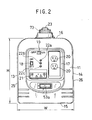
- Fig. 2 is an elevational view of Fi. 1;
- Fig. 3 is a side view of Fig. 1;
- Fig. 4 is a rear view of Fig. 1;
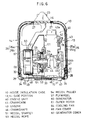
- Fig. 5 is a sectional view taken along a right side portion of Fig. 1;
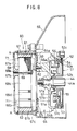
- Fig. 6 is a sectional view taken along a rear portion of Fig. 1;
- Fig. 7 is a partially sectional view taken along a top portion of Fig. 1;
- Fig. 8 is an enlarged sectional view of Fig. 6;
- Fig. 9 is a front perspective view of an engine unit in a noise insulation case;
- Fig. 10 is a front perspective view of the engine unit shown in Fig. 9 when a fuel tank is removed;
- Fig. 11 is a front perspective view of an engine generator when an engine unit is used as a utility engine;
- Fig. 12 is a rear perspective view of the engine unit shown in Fig. 11; and
- Fig. 13 is a sectional view of a recoil starter.
-
- Referring now to Fig. 1, a
noise insulation case 10 includes afront section 11, arear section 12, a left andright side sections bottom section 15 and atop section 16, having a rectangular parallelepiped configuration. Thefront section 11 is a front end of thenoise insulation case 10 and therear section 12 is a rear end thereof. Thefront section 11 has a recess in which acontrol panel 17 is provided. Anengine switch 18, anautomatic throttle switch 19, anAC output terminal 20 for outputting generated power and aDC output terminal 21 for charging batteries are provided on thecontrol panel 17, respectively. - Further, on the
control panel 17, there are provided anoperation indicator 22a for indicating an operative generator, anoil indicator 22b for warning against a shortage of engine oil, anoverload indicator 22c for indicating an overload of the engine. On thetop section 16, there is provided a stick like carryinghandle 23 to be griped when a worker carries the engine generator. Thecarrying handle 23 extends in a longitudinal direction of thenoise insulation case 10 and is connected at front and rear ends thereof with connectingsections top section 16. - The
noise insulation case 10 comprises afirst case member 10a and asecond case member 10b molded by synthetic resin. Thefirst case member 10a comprises afront section 11, a part of bothside sections bottom section 15, a part of thetop section 16 and is integrally formed therewith. Thesecond case member 10b comprises arear section 12, the rest part of bothside sections bottom section 15, the rest part of thetop section 16 and is integrally formed therewith. Therespective case members end surfaces end surfaces - Referring to Figs. 5, 6 and 7, an opening is provided in the left and
right side sections noise insulation case 10, respectively and the opening extends to a part of thetop section 16. In order to open and close the left and right openings, L-shaped covers shaped covers top section 16 and a portion constituting a part of theside sections shaped covers inner plates 25a, 26a andouter plates hook 28 for engaging with a groove formed in thetop section 16 in the upper ends of the L-shaped covers shaped covers - The
case member bottom section 15 with abase plate 31 fabricated by sheet metal. Thebase plate 31 has a rectangular shape and has a vertical section bent upward 32 on both sides thereof. Further, thebase plate 31 has afitting end 33 with a slit at front and rear edges thereof, respectively and has afitting end 34 with a slit on left and right edges thereof, respectively. Thecase member bottom section 15 between the slits of thefitting ends base plate 31. - On the other hand, in order to connect two
case members handle 23, as shown in Fig. 5, aninternal thread member 35 having a taped hole is formed by insert molding in afirst handle part 23b integrally molded with thecase member 10b. Further, athrough hole 36b having a larger diameter than the taped hole is formed in thefirst handle part 23b adjacent to and at the front of theinternal thread member 35. On the other hand, asecond handle part 23a integrally molded with thecase member 10a has a throughhole 36a having the same diameter as the throughhole 36b. Further, alarge diameter hole 36c is formed in thesecond handle part 23a on the frontal side of thethrough hole 36a. Accordingly, when anexternal thread member 37 is inserted into the throughhole 36a from thelarge diameter hole 36c and is screwed in theinternal thread member 35, thecase member 10a is connected with thecase member 10b at the boundary of thefirst handle part 23b and thesecond handle part 23a, thus a stick likehandle 23 is assembled by the connection of bothhandle parts - Thus, since two
case members bottom section 31 with each other and also connected at the boundary of twohandle parts external thread member 37, no screw heads can be observed from the outside of thenoise insulation case 10, this structure providing an aethetically good appearance. In case where thenoise insulation case 10 is divided into two left and right parts, a larger number of screw members for tightening these parts is needed than the number of screw members in case of this method of dividing thenoise insulation case 10 in the longitudinal direction. - As shown in Fig. 6, an
engine unit 40 has anengine 43 incorporating acrankcase 41 and acylinder 42 covered with ahead cover 42a. Theengine 43 is mounted in thenoise insulation case 10 in such a manner that acrankshaft 44 incorporated in thecrankcase 41 directs in a widthwise direction of thenoise insulation case 10. Thecrankshaft 44 extends laterally approximately under the longitudinally middle portion of thehandle 23. As shown in Fig. 6, theengine 43 is mounted being biased toward theside section 13. Thecrankshaft 44 is rotatably supported at oneend section 44a thereof by abearing 45 on a magneto side of thecrankcase 41 and is rotatably supported at theother end section 44b thereof by abearing 46 on the opposite side of thebearing 45. The oneend section 44a projects outside of thecrankcase 41 and theother end section 44b is covered with adetachable shaft cover 47. Theengine unit 40 is mounted on thebase plate 31 through a plurality ofvibration isolating rubbers 48 and thebase plate 31 has rubber mounts 49 underneath. - Referring to Fig. 8, a
recoil starter 51 is mounted on the magneto side of theengine 43. Therecoil starter 51 has arecoil holder 52 integrally formed with adisc section 52a and acylinder section 52b. Thedisc section 52a is secured to theengine 43 by a plurality of bolts going through a plurality ofinstallation holes 52c. The oneend section 44a of thecrankshaft 44 penetrates the inside of thecylinder section 52b through a gap. Arecoil pulley 54 is rotatably mounted on the outside of thecylinder section 52b and arecoil rope 53 is wound around therecoil pulley 54. Also, areturn spring 55 is provided on arecoil holder 52 to apply the spring force in a winding direction of therecoil rope 53. Further, arotary pin 56a having anengagement hook 56 is provided is rotatably mounted on therecoil pulley 54. When therecoil pulley 54 is rotated by therecoil rope 53, therotary pin 56a rotates such that theengagement hook 56 is lifted up in an outward, radial direction by centrifugal force. - A
flywheel 57 is mounted on a projection of thecrankshaft 44. Theflywheel 57 includes aboss section 57a fixed to thecrankshaft 44 through a key and adisc section 57b provided around theboss section 57a. Further, anengagement ring section 57c is provided around thedisc section 57b. A protrusion section is formed on the inner periphery surface of theengagement ring section 57c in a radial inner direction so as to be engaged with theengagement hook 56. Accordingly, when therecoil rope 53 is drawn out to rotate thecrankshaft 44, theengagement hook 56 is engaged with the protrusion section by centrifugal force and thecrankshaft 44 is started to rotate through theflywheel 57. A part of therecoil pulley 54 is accommodated inside of theengagement ring 57a of theflywheel 57 and therefore theflywheel 57 constitutes a part of therecoil starter 51. As a result, a total width of theflywheel 57 and therecoil starter 51 can be reduced. Since therecoil starter 51 is mounted on the root of the projection section of thecrankshaft 44, the pulling force of the rope can be converted into a rotation force without giving a large bending force to thecrankshaft 44. - There are provided a plurality of connecting
sections 59 projecting in an opposite direction to theengagement ring section 57c in theflywheel 57 and anouter rotor 61 of agenerator 60 is mounted on the connectingsections 59 throughbolts 62. Theouter rotor 61 comprises adisc section 61a which is connected with the connectingsection 59 and acylinder section 61b integrally formed with thedisc section 61a. A plurality ofmagnets 63 are fixed to the inner periphery surface of thecylinder section 61b at a specified interval in a circumferential direction. - A cooling
fan 64 is disposed between theflywheel 57 and theouter rotor 61. The coolingfan 64 has adisc section 64a including a ventilation guide hole at the center thereof and a plurality of fan blades 64b integrally provided on the surface of thedisc section 64a. Thedisc section 64a is interleaved between thedisc section 61a of theouter rotor 61 and the connectingsection 59 of theflywheel 57. Thedisc section 64a is secured to theouter rotor 61 by fitting an engagement projection 65 to an engagement hole formed on thedisc section 61a. - The cooling
fan 64 is enclosed by afan cover 66 fixed to theengine 43. Thisfan cover 66 functions as a duct for guiding air and cooling air discharged from the coolingfan 64 is guided toward theengine 43. Agenerator cover 67 is secured to thefan cover 66 and has adisc section 67b including a lot ofventilation holes 67a and acylinder section 67c integrally formed with thedisc section 67b. Thegenerator cover 67 is secured to the fan cover at thecylinder section 67c thereof. - A
stator 68 is disposed in theouter rotor 61 and is fixed to thegenerator cover 67 through a plurality ofbolts 69 penetratinginstallation holes 68a of thegenerator cover 67. Thestator 68 is formed by piling up a lot of steel plates and a lot ofslits 68b extending in a radial direction are formed around the outer periphery of thestator 68. Acoil 71 is wound around twoadjacent slits 68b, respectively. Further, thestator 68 has aventilation hole 68c in the center thereof and also has a plurality ofventilation holes 68d extending in the radial direction. - Thus, the
generator 60 is an outer rotor type multi-pole generator characterized in a small axial length. Further, since theflywheel 57 is one of components of therecoil starter 51, the lengthwise size of theengine unit 40, that is, the widthwise size of the engine generator can be shortened. As shown in Fig. 5, aninverter unit 70 is mounted on the bottom surface of thenoise insulation case 10. Theinverter unit 70 is for controlling output of thegenerator 60 and for converting into alternating current having specified frequency. - The
recoil starter 51 is located in the center of the engine generator when viewed from the front and thecrankshaft 44 directs in the widthwise direction of thenoise insulation case 10. Therefore, arecoil knob 53a can be disposed in the center of thefront section 11 of thenoise insulation case 10, as shown in Fig. 1 and Fig. 2. Since therecoil knob 53a is disposed at the lower part of thecontrol panel 17, an operator can perform all operations, starting, stopping and the like from the front side. - Referring to Fig. 9, a
fuel tank 72 is disposed in thenoise insulation case 10. Further, afiller inlet 72a of thefuel tank 72 is provided on thetop section 16 and atank cap 73 is screwed on thefiller inlet 72a. Thefuel tank 72 is located at the front side of thenoise insulation case 10 on the opposite side of theengine 43. - An
air cleaner 74 for cleaning air to be supplied to theengine 43 is disposed on the frontal side of thenoise insulation case 10. As shown in Fig. 12, theair cleaner 74 is attached to theengine 43 through anintake pipe 75 extending straight backward and acarburetor 76 is mounted on theintake pipe 75. On the other hand, amuffler 77 is disposed on the rear side of thenoise insulation case 10 and is connected with theengine 43 through anexhaust pipe 78. Anexhaust outlet 79 formed on the back side of themuffler 77 communicates with anexhaust outlet 79a formed on theback section 12 of thenoise insulation case 10 and exhaust gas of theengine 43 is discharged from the back side of thenoise insulation case 10. Thus, since theair cleaner 74 is disposed on the frontal side of thenoise insulation case 10 and themuffler 77 is disposed on the rear side, the widthwise length of thenoise insulation case 10 can be reduced. - An
ignition coil 80 built in a plug cap is attached to thecylinder 42. When maintenance is performed on the plug cap, theair cleaner 74 and the like, the L-shapedcover 25 is displaced. Then, if it is not necessary to displace the L-shapedcover 26 on the opposite side, the L-shapedcover 26 may be a fixed type. - A plurality of cooling
air inlets 81 is formed at the front end of thenoise insulation case 10 and a plurality of coolingair outlets 82 are formed at therear section 12. As shown in Fig. 5, the coolingair outlets 82 is constituted by louvers slanted downward. When operated, as shown in Fig. 7, cooling air introduced from the front end of thenoise insulation case 10 and aninverter unit 70 is efficiently cooled by the cooling air. A part of the cooling air is sucked into theengine 43 through theair cleaner 74. On the other hand, the cooling air generated by the coolingfan 64 is introduced from either of theside sections noise insulation case 10 into a plurality of theventilation holes stator 68 through theventilation holes 67a formed on thegenerator cover 67. - Next, the cooling air is guided by the
fan cover 66, blowing the surrounding of theengine 43. Further, after blowing theengine 43, the cooling air turns its stream in the longitudinal direction towards a coolingair outlet 82 provided in therear section 12 and cools themuffler 77. In order to make a stable stream of the cooling air toward themuffler 77, there is provided a partition for discriminating low temperature air from high temperature air in thenoise insulation case 10. - As shown in Fig. 6, since the
engine 43 is mounted on the right side of thenoise insulation case 10 when viewed from the front side and thegenerator 60, therecoil starter 51 and the coolingfan 64 are disposed on the left side, a lateral center of gravity comes around the lateral center of thenoise insulation case 10. On the other hand, since theair cleaner 74 is disposed on the front side of thenoise insulation case 10, themuffler 77 is disposed on the rear side and theengine 43, thegenerator 60 are situated in the center, a longitudinal center of gravity comes around the longitudinal center of thenoise insulation case 10. That is, thehandle 23 is positioned approximately on the center of gravity of the engine generator. As a result, thus constituted engine generator has a good portability. - Fig. 11 is a perspective view of a utility engine modified from the
engine unit 40 for the engine generator described before when viewed from the front side, Fig 12 is a perspective view of the utility engine of Fig. 11 when viewed from the rear side, and Fig. 13 is a sectional view showing a recoil starter of the utility engine of Fig. 11. - As shown in Fig. 13, the
crankshaft 44 of the utility engine is longer than that of the engine generator. Both ends 44a, 44b of thecrankshaft 44 project from thecrankcase 41, respectively. Anengine cover 85 having similar configuration to thefan cover 66 is fixed to theengine unit 40 and aholder 87 is secured to astarter cover 86 attached to theengine cover 85. Further, arecoil pulley 88 around which arecoil rope 53 is wound is rotatably mounted on theholder 87 and therecoil pulley 88 is connected with oneend 44a of thecrankshaft 44 through acoupling 89. Further, aflywheel 57 is mounted on therecoil pulley 88. - In case where the
engine unit 40 is used as a utility engine, thenoise insulation case 10 is removed. Theother end 44b of thecrankshaft 44 projects from thecrankcase 41 and miscellaneous driven members such as a hydraulic pump, a compressor, a rammer and the like are connected with this projection. As shown in Fig. 13, the configuration of therecoil starter 51 differs from that of the engine generator but other major components of theengine unit 40 such as theengine 43,air cleaner 74,muffler 77 and the like, are identical in either case of a utility engine or an engine generator. - The
air cleaner 74 and themuffler 77 are identical to those used in the engine generator. Theair cleaner 74 is disposed on the front side and themuffler 77 is disposed on the rear side in the same manner as in case of the engine generator. Accordingly, themuffler 77 or theair cleaner 74 are not interfered with on an extension line of bothends crankshaft 44 and theother end 44b of thecrankshaft 44 can be connected with miscellaneous driven members. - In case of the engine generator according to the present invention, since the
air cleaner 74 and themuffler 77 are arranged with theengine 43 between and theengine unit 40 is mounted in such a manner thecrankshaft 44 is oriented in a widthwise direction of thenoise insulation case 10, the width of the engine generator can be shortened and as a result a compact engine generator can be realized. Further, theengine unit 40 can be converted into a utility engine without making a large modification. - While the present invention has been disclosed in terms of the preferred embodiment in order to facilitate better understanding of the invention, it should be appreciated that the invention can be embodied in various ways without departing from the principle of the invention. Therefore, the invention should be understood to include all possible embodiments which can be embodied without departing from the principle of the invention set out in the appended claims.
Claims (3)
- An engine generator having an engine convertible into a utility engine, comprising:a noise insulation case for accommodating said engine generator;a crankshaft of said engine arranged in a widthwise direction of said noise insulation case;a one end of said crankshaft extending from said engine toward one side of said noise insulation case;an other end of said crankshaft extending from said engine toward the other side of said noise insulation case;a recoil starter provided on said one end side of said crankshaft;a flywheel including said recoil starter therein and provided on said one end of said crankshaft;a generator provided on said one end side of said crankshaft;an air cleaner arranged on the front side of said noise insulation case; andan muffler arranged on the rear side of said noise insulation case.
- The engine generator according to claim 1, wherein
said other end of said crankshaft is connected with miscellaneous driven members when said engine is used as a utility engine. - The engine generator according to claim 1 or 2, wherein
said recoil starter is disposed inside of said flywheel and said generator is disposed outside of said flywheel.
Applications Claiming Priority (2)
| Application Number | Priority Date | Filing Date | Title |
|---|---|---|---|
| JP2000378898 | 2000-12-13 | ||
| JP2000378898A JP3916393B2 (en) | 2000-12-13 | 2000-12-13 | Engine generator |
Publications (3)
| Publication Number | Publication Date |
|---|---|
| EP1215379A2 true EP1215379A2 (en) | 2002-06-19 |
| EP1215379A3 EP1215379A3 (en) | 2003-05-02 |
| EP1215379B1 EP1215379B1 (en) | 2007-10-31 |
Family
ID=18847377
Family Applications (1)
| Application Number | Title | Priority Date | Filing Date |
|---|---|---|---|
| EP01129275A Expired - Lifetime EP1215379B1 (en) | 2000-12-13 | 2001-12-12 | Engine generator |
Country Status (4)
| Country | Link |
|---|---|
| US (1) | US6661107B2 (en) |
| EP (1) | EP1215379B1 (en) |
| JP (1) | JP3916393B2 (en) |
| DE (1) | DE60131130T2 (en) |
Cited By (2)
| Publication number | Priority date | Publication date | Assignee | Title |
|---|---|---|---|---|
| EP1975395A2 (en) | 2007-03-30 | 2008-10-01 | HONDA MOTOR CO., Ltd. | General-purpose internal combustion engine |
| EP3219953A1 (en) * | 2016-03-16 | 2017-09-20 | Honda Motor Co., Ltd. | Engine-driven working machine |
Families Citing this family (31)
| Publication number | Priority date | Publication date | Assignee | Title |
|---|---|---|---|---|
| US7034410B2 (en) * | 2000-06-23 | 2006-04-25 | Gino Kennedy | Compact auxiliary power generator |
| US6917121B2 (en) * | 2002-03-29 | 2005-07-12 | Yamaha Hatsudoki Kabushiki Kaisha | Power generator unit |
| JP4246517B2 (en) * | 2003-02-17 | 2009-04-02 | 富士重工業株式会社 | Engine generator |
| WO2005036721A2 (en) | 2003-10-06 | 2005-04-21 | Edward Woods | Power generation systems and methods of generating power |
| USD520038S1 (en) * | 2004-01-02 | 2006-05-02 | Esab Ab | Welding machine |
| US7264069B2 (en) * | 2004-10-11 | 2007-09-04 | Briggs And Stratton Corporation | Vehicle or lawn and garden maintenance equipment having a generator, and power takeoff assembly for a vehicle or lawn and garden maintenance equipment |
| JP4530830B2 (en) | 2004-12-15 | 2010-08-25 | ヤマハモーターパワープロダクツ株式会社 | Engine generator |
| JP4484691B2 (en) * | 2004-12-22 | 2010-06-16 | ヤマハモーターパワープロダクツ株式会社 | Engine generator |
| JP2006188980A (en) | 2005-01-06 | 2006-07-20 | Yamaha Motor Co Ltd | Engine generator |
| US7549192B2 (en) * | 2006-01-17 | 2009-06-23 | Coeur, Inc. | Handle and method of manufacture |
| USD567175S1 (en) | 2006-08-25 | 2008-04-22 | Briggs & Stratton Corporation | Inverter generator |
| US7492050B2 (en) * | 2006-10-24 | 2009-02-17 | Briggs & Stratton Corporation | Cooling system for a portable generator |
| US7424886B1 (en) * | 2007-02-06 | 2008-09-16 | Herzer Bernardo J | Portable gas powered internal combustion engine arrangement |
| US8656884B1 (en) | 2007-02-06 | 2014-02-25 | Bernardo J. Herzer | Portable gas powered internal combustion engine arrangement |
| US9121372B2 (en) * | 2007-02-06 | 2015-09-01 | Bernardo J. Herzer | Portable gas powered internal combustion engine arrangement |
| US9765918B2 (en) | 2007-02-06 | 2017-09-19 | Bernardo J. Herzer | Portable gas powered internal combustion engine arrangement |
| US8921735B2 (en) * | 2007-04-30 | 2014-12-30 | Illinois Tool Works Inc. | Portable generator and air compressor mounting arrangement |
| US7699027B2 (en) * | 2007-08-17 | 2010-04-20 | Yunfeng Ma | Portable generator |
| US7878170B1 (en) | 2007-10-24 | 2011-02-01 | Herzer Bernardo J | LPG fueled internal combustion engine powered devices |
| TWD132753S1 (en) * | 2008-08-01 | 2010-01-01 | 本田技研工業股份有限公司 | Generator |
| US8511286B2 (en) | 2009-08-03 | 2013-08-20 | Bernardo J. Herzer | Carburetor arrangement |
| USD646634S1 (en) * | 2010-05-05 | 2011-10-11 | Cummins Power Generation Ip, Inc. | Genset |
| US9393568B2 (en) * | 2013-03-15 | 2016-07-19 | Richard Walter Finney | Mobile wood chipper |
| JP6069088B2 (en) * | 2013-04-30 | 2017-01-25 | 富士重工業株式会社 | Soundproof engine |
| USD712834S1 (en) * | 2013-11-20 | 2014-09-09 | Midland Power Inc. | Power generator inverter |
| JP6687432B2 (en) * | 2016-03-16 | 2020-04-22 | 本田技研工業株式会社 | Engine driven work machine |
| CN108374716B (en) * | 2018-01-29 | 2023-11-24 | 江西永骏泰新能源科技有限公司 | Outdoor gas generator |
| CN109681342A (en) * | 2019-02-15 | 2019-04-26 | 重庆华世丹动力科技股份有限公司 | The full bag engine of input type |
| CN209545211U (en) | 2019-04-26 | 2019-10-25 | 深圳市锦丰泰科技有限公司 | A kind of accumulation power supply |
| USD916658S1 (en) * | 2019-04-26 | 2021-04-20 | Shenzhen Chifrog Technology Co., Ltd | Power pack station |
| USD1123849S1 (en) * | 2024-05-16 | 2026-04-28 | Chongqing Dinking Power Machinery Co., Ltd | Inverter generator |
Citations (2)
| Publication number | Priority date | Publication date | Assignee | Title |
|---|---|---|---|---|
| JPS6166631U (en) | 1984-10-09 | 1986-05-07 | ||
| JPH11200861A (en) | 1998-01-19 | 1999-07-27 | Honda Motor Co Ltd | Engine generator |
Family Cites Families (15)
| Publication number | Priority date | Publication date | Assignee | Title |
|---|---|---|---|---|
| GB986740A (en) * | 1962-10-24 | 1965-03-24 | Honda Gijutsu Kenkyusho Kk | Improvements in or relating to portable internal combustion engines |
| JPS58197417A (en) * | 1982-05-12 | 1983-11-17 | Fuji Heavy Ind Ltd | Engine-driven generator |
| GB2139429B (en) * | 1983-03-18 | 1986-08-13 | Honda Motor Co Ltd | Portable generators |
| GB2141782B (en) * | 1983-05-11 | 1987-01-07 | Honda Motor Co Ltd | Portable engine-generator sets |
| JPS6140425A (en) * | 1984-07-31 | 1986-02-26 | Yanmar Diesel Engine Co Ltd | Case containing type engine generator |
| JPS6166631A (en) | 1984-09-11 | 1986-04-05 | Ibiden Co Ltd | Continuous lapping technique of decorative sheet for covering furniture and/or building material |
| US4657290A (en) * | 1984-10-03 | 1987-04-14 | Linden Craig L | Co-generation plant module system |
| US4647835A (en) * | 1984-12-19 | 1987-03-03 | Kawasaki Jukogyo Kabushiki Kaisha | Portable generator |
| DE3501185A1 (en) * | 1985-01-16 | 1986-07-17 | Robert Bosch Gmbh, 7000 Stuttgart | Generator set |
| US4827147A (en) * | 1986-11-12 | 1989-05-02 | Honda Giken Kogyo Kabushiki Kaisha | Engine-powered portable working apparatus |
| US5890460A (en) * | 1995-05-08 | 1999-04-06 | Ball; Ronald C. | Electrical generator set |
| JP3800372B2 (en) * | 1997-07-24 | 2006-07-26 | 本田技研工業株式会社 | Engine generator |
| JP3815703B2 (en) * | 1997-07-24 | 2006-08-30 | 本田技研工業株式会社 | Engine generator |
| US6119636A (en) * | 1999-06-11 | 2000-09-19 | Fan; Guo Xiang | Portable generator |
| JP2001221054A (en) * | 2000-02-09 | 2001-08-17 | Fuji Heavy Ind Ltd | Engine generator |
-
2000
- 2000-12-13 JP JP2000378898A patent/JP3916393B2/en not_active Expired - Fee Related
-
2001
- 2001-12-12 EP EP01129275A patent/EP1215379B1/en not_active Expired - Lifetime
- 2001-12-12 US US10/012,414 patent/US6661107B2/en not_active Expired - Fee Related
- 2001-12-12 DE DE60131130T patent/DE60131130T2/en not_active Expired - Lifetime
Patent Citations (2)
| Publication number | Priority date | Publication date | Assignee | Title |
|---|---|---|---|---|
| JPS6166631U (en) | 1984-10-09 | 1986-05-07 | ||
| JPH11200861A (en) | 1998-01-19 | 1999-07-27 | Honda Motor Co Ltd | Engine generator |
Cited By (6)
| Publication number | Priority date | Publication date | Assignee | Title |
|---|---|---|---|---|
| EP1975395A2 (en) | 2007-03-30 | 2008-10-01 | HONDA MOTOR CO., Ltd. | General-purpose internal combustion engine |
| EP1975395A3 (en) * | 2007-03-30 | 2011-11-23 | Honda Motor Co., Ltd. | General-purpose internal combustion engine |
| EP3219953A1 (en) * | 2016-03-16 | 2017-09-20 | Honda Motor Co., Ltd. | Engine-driven working machine |
| CN107201941A (en) * | 2016-03-16 | 2017-09-26 | 本田技研工业株式会社 | Motor driven operator |
| US10260456B2 (en) | 2016-03-16 | 2019-04-16 | Honda Motor Co., Ltd. | Engine-driven working machine |
| CN107201941B (en) * | 2016-03-16 | 2019-08-30 | 本田技研工业株式会社 | engine driven work machine |
Also Published As
| Publication number | Publication date |
|---|---|
| EP1215379B1 (en) | 2007-10-31 |
| DE60131130T2 (en) | 2008-02-21 |
| JP3916393B2 (en) | 2007-05-16 |
| US6661107B2 (en) | 2003-12-09 |
| JP2002180843A (en) | 2002-06-26 |
| EP1215379A3 (en) | 2003-05-02 |
| US20020070552A1 (en) | 2002-06-13 |
| DE60131130D1 (en) | 2007-12-13 |
Similar Documents
| Publication | Publication Date | Title |
|---|---|---|
| EP1215379B1 (en) | Engine generator | |
| EP1249590A2 (en) | Engine generator | |
| EP2758646B1 (en) | Engine and engine-operated working machine | |
| EP0197487A2 (en) | Portable engine unit | |
| US6431126B2 (en) | Engine generator | |
| EP1146211B1 (en) | Engine generator | |
| US4815430A (en) | Portable engine unit | |
| CN103206303A (en) | Engine and engine working machine | |
| JP2005042644A (en) | Engine generator | |
| JP2001221055A (en) | Engine generator | |
| JP3206633B2 (en) | Engine generator | |
| JPH0346177Y2 (en) | ||
| JP2002180842A (en) | Soundproof engine generator | |
| JPH0526305Y2 (en) | ||
| JPH0248698Y2 (en) | ||
| CN106662038B (en) | Two stroke engine, engine type working rig | |
| JP2002180844A (en) | Soundproof engine generator | |
| US20050173926A1 (en) | Generating apparatus | |
| JP2002295265A (en) | Soundproof engine generator | |
| JP3926252B2 (en) | Engine generator | |
| JPH0229224Y2 (en) | ||
| JPH036833Y2 (en) | ||
| JPH0245468Y2 (en) | ||
| JP2002295266A (en) | Engine generator | |
| JP3194565B2 (en) | Engine generator |
Legal Events
| Date | Code | Title | Description |
|---|---|---|---|
| PUAI | Public reference made under article 153(3) epc to a published international application that has entered the european phase |
Free format text: ORIGINAL CODE: 0009012 |
|
| AK | Designated contracting states |
Kind code of ref document: A2 Designated state(s): AT BE CH CY DE DK ES FI FR GB GR IE IT LI LU MC NL PT SE TR |
|
| AX | Request for extension of the european patent |
Free format text: AL;LT;LV;MK;RO;SI |
|
| PUAL | Search report despatched |
Free format text: ORIGINAL CODE: 0009013 |
|
| AK | Designated contracting states |
Designated state(s): AT BE CH CY DE DK ES FI FR GB GR IE IT LI LU MC NL PT SE TR |
|
| AX | Request for extension of the european patent |
Extension state: AL LT LV MK RO SI |
|
| 17P | Request for examination filed |
Effective date: 20030715 |
|
| AKX | Designation fees paid |
Designated state(s): DE FR GB |
|
| GRAP | Despatch of communication of intention to grant a patent |
Free format text: ORIGINAL CODE: EPIDOSNIGR1 |
|
| GRAS | Grant fee paid |
Free format text: ORIGINAL CODE: EPIDOSNIGR3 |
|
| GRAA | (expected) grant |
Free format text: ORIGINAL CODE: 0009210 |
|
| RIN1 | Information on inventor provided before grant (corrected) |
Inventor name: HIGUCHI, MASAAKI Inventor name: SATIO, SHINICHI |
|
| AK | Designated contracting states |
Kind code of ref document: B1 Designated state(s): DE FR GB |
|
| REG | Reference to a national code |
Ref country code: GB Ref legal event code: FG4D |
|
| REF | Corresponds to: |
Ref document number: 60131130 Country of ref document: DE Date of ref document: 20071213 Kind code of ref document: P |
|
| ET | Fr: translation filed | ||
| PLBE | No opposition filed within time limit |
Free format text: ORIGINAL CODE: 0009261 |
|
| STAA | Information on the status of an ep patent application or granted ep patent |
Free format text: STATUS: NO OPPOSITION FILED WITHIN TIME LIMIT |
|
| 26N | No opposition filed |
Effective date: 20080801 |
|
| PGFP | Annual fee paid to national office [announced via postgrant information from national office to epo] |
Ref country code: GB Payment date: 20101208 Year of fee payment: 10 |
|
| PGFP | Annual fee paid to national office [announced via postgrant information from national office to epo] |
Ref country code: DE Payment date: 20101208 Year of fee payment: 10 |
|
| PGFP | Annual fee paid to national office [announced via postgrant information from national office to epo] |
Ref country code: FR Payment date: 20111219 Year of fee payment: 11 |
|
| GBPC | Gb: european patent ceased through non-payment of renewal fee |
Effective date: 20121212 |
|
| REG | Reference to a national code |
Ref country code: FR Ref legal event code: ST Effective date: 20130830 |
|
| REG | Reference to a national code |
Ref country code: DE Ref legal event code: R119 Ref document number: 60131130 Country of ref document: DE Effective date: 20130702 |
|
| PG25 | Lapsed in a contracting state [announced via postgrant information from national office to epo] |
Ref country code: DE Free format text: LAPSE BECAUSE OF NON-PAYMENT OF DUE FEES Effective date: 20130702 |
|
| PG25 | Lapsed in a contracting state [announced via postgrant information from national office to epo] |
Ref country code: FR Free format text: LAPSE BECAUSE OF NON-PAYMENT OF DUE FEES Effective date: 20130102 Ref country code: GB Free format text: LAPSE BECAUSE OF NON-PAYMENT OF DUE FEES Effective date: 20121212 |