EP1215290A2 - Heat treated stainless steel hydraulic components and method for making same - Google Patents
Heat treated stainless steel hydraulic components and method for making same Download PDFInfo
- Publication number
- EP1215290A2 EP1215290A2 EP01129447A EP01129447A EP1215290A2 EP 1215290 A2 EP1215290 A2 EP 1215290A2 EP 01129447 A EP01129447 A EP 01129447A EP 01129447 A EP01129447 A EP 01129447A EP 1215290 A2 EP1215290 A2 EP 1215290A2
- Authority
- EP
- European Patent Office
- Prior art keywords
- stainless steel
- heat treated
- component
- recited
- hydraulic
- Prior art date
- Legal status (The legal status is an assumption and is not a legal conclusion. Google has not performed a legal analysis and makes no representation as to the accuracy of the status listed.)
- Withdrawn
Links
Images
Classifications
-
- C—CHEMISTRY; METALLURGY
- C21—METALLURGY OF IRON
- C21D—MODIFYING THE PHYSICAL STRUCTURE OF FERROUS METALS; GENERAL DEVICES FOR HEAT TREATMENT OF FERROUS OR NON-FERROUS METALS OR ALLOYS; MAKING METAL MALLEABLE, e.g. BY DECARBURISATION OR TEMPERING
- C21D6/00—Heat treatment of ferrous alloys
- C21D6/002—Heat treatment of ferrous alloys containing Cr
-
- C—CHEMISTRY; METALLURGY
- C22—METALLURGY; FERROUS OR NON-FERROUS ALLOYS; TREATMENT OF ALLOYS OR NON-FERROUS METALS
- C22C—ALLOYS
- C22C38/00—Ferrous alloys, e.g. steel alloys
- C22C38/18—Ferrous alloys, e.g. steel alloys containing chromium
- C22C38/40—Ferrous alloys, e.g. steel alloys containing chromium with nickel
- C22C38/42—Ferrous alloys, e.g. steel alloys containing chromium with nickel with copper
-
- C—CHEMISTRY; METALLURGY
- C22—METALLURGY; FERROUS OR NON-FERROUS ALLOYS; TREATMENT OF ALLOYS OR NON-FERROUS METALS
- C22C—ALLOYS
- C22C38/00—Ferrous alloys, e.g. steel alloys
- C22C38/18—Ferrous alloys, e.g. steel alloys containing chromium
- C22C38/40—Ferrous alloys, e.g. steel alloys containing chromium with nickel
- C22C38/44—Ferrous alloys, e.g. steel alloys containing chromium with nickel with molybdenum or tungsten
-
- C—CHEMISTRY; METALLURGY
- C23—COATING METALLIC MATERIAL; COATING MATERIAL WITH METALLIC MATERIAL; CHEMICAL SURFACE TREATMENT; DIFFUSION TREATMENT OF METALLIC MATERIAL; COATING BY VACUUM EVAPORATION, BY SPUTTERING, BY ION IMPLANTATION OR BY CHEMICAL VAPOUR DEPOSITION, IN GENERAL; INHIBITING CORROSION OF METALLIC MATERIAL OR INCRUSTATION IN GENERAL
- C23C—COATING METALLIC MATERIAL; COATING MATERIAL WITH METALLIC MATERIAL; SURFACE TREATMENT OF METALLIC MATERIAL BY DIFFUSION INTO THE SURFACE, BY CHEMICAL CONVERSION OR SUBSTITUTION; COATING BY VACUUM EVAPORATION, BY SPUTTERING, BY ION IMPLANTATION OR BY CHEMICAL VAPOUR DEPOSITION, IN GENERAL
- C23C8/00—Solid state diffusion of only non-metal elements into metallic material surfaces; Chemical surface treatment of metallic material by reaction of the surface with a reactive gas, leaving reaction products of surface material in the coating, e.g. conversion coatings, passivation of metals
- C23C8/02—Pretreatment of the material to be coated
-
- F—MECHANICAL ENGINEERING; LIGHTING; HEATING; WEAPONS; BLASTING
- F15—FLUID-PRESSURE ACTUATORS; HYDRAULICS OR PNEUMATICS IN GENERAL
- F15B—SYSTEMS ACTING BY MEANS OF FLUIDS IN GENERAL; FLUID-PRESSURE ACTUATORS, e.g. SERVOMOTORS; DETAILS OF FLUID-PRESSURE SYSTEMS, NOT OTHERWISE PROVIDED FOR
- F15B13/00—Details of servomotor systems ; Valves for servomotor systems
-
- C—CHEMISTRY; METALLURGY
- C21—METALLURGY OF IRON
- C21D—MODIFYING THE PHYSICAL STRUCTURE OF FERROUS METALS; GENERAL DEVICES FOR HEAT TREATMENT OF FERROUS OR NON-FERROUS METALS OR ALLOYS; MAKING METAL MALLEABLE, e.g. BY DECARBURISATION OR TEMPERING
- C21D2261/00—Machining or cutting being involved
-
- C—CHEMISTRY; METALLURGY
- C21—METALLURGY OF IRON
- C21D—MODIFYING THE PHYSICAL STRUCTURE OF FERROUS METALS; GENERAL DEVICES FOR HEAT TREATMENT OF FERROUS OR NON-FERROUS METALS OR ALLOYS; MAKING METAL MALLEABLE, e.g. BY DECARBURISATION OR TEMPERING
- C21D9/00—Heat treatment, e.g. annealing, hardening, quenching or tempering, adapted for particular articles; Furnaces therefor
- C21D9/0068—Heat treatment, e.g. annealing, hardening, quenching or tempering, adapted for particular articles; Furnaces therefor for particular articles not mentioned below
Definitions
- the present invention relates in general to stainless steel hydraulic components, and more particularly to a method of using and manufacturing hydraulic components from pre-heat treated stainless steel.
- Hydraulic components must be produced or finished within very close tolerances, i.e., to precision finished dimensions.
- most hydraulic components like check valves, poppet valves, or sliding spool valves are produced from carbon or alloy steel and are subjected to a variety of machining, turning, grinding, or cutting process steps necessary to form the component to its precision finished dimension for the completed product.
- the typical process usually requires at least one turning or machining step followed by a final heat treatment step to provide suitable hardenability to the hydraulic component.
- it is more difficult to establish part finishes, geometrical requirements, and dimensional tolerance constraints. This can result in the requirement for more processing time and cost involved in producing a desired part from a selected carbon steel material.
- Stainless steel is a material currently used primarily in corrosive environments. Stainless steel is commonly understood to mean a corrosion resistant alloy steel containing approximately 10.5% or more on a weight percent basis, chromium (Cr). Stainless steel (SS) offers strength (approximately 50% stronger than low carbon steels), heat and corrosion resistance, and low maintenance.
- Stainless steel materials are widely used for specific industry applications like fasteners, spindles, nozzles, shafts, springs, surgical instruments, etc. as well as in many aerospace and automotive applications. Cast stainless steel has also been employed in some hydraulic valve applications, like fabricating the body and bonnet, wedge, seat ring, stem gland, bonnet bush, yoke sleeve, etc.
- the improved hydraulic components should be made from stainless steel and be more durable, more corrosion resistant, and exhibit improved leak performance over time.
- the improved method should eliminate secondary process steps along with the extra costs associated therewith. Such a method would make a stainless steel material a cost-effective alternative after processing costs and life cycle cost are compared to other materials.
- Another object of the present invention is to provide a method for making a stainless steel hydraulic component that offers improved performance, corrosion protection, durability, and low maintenance throughout the manufacturing process and life cycle of the product.
- Another object of the present invention to provide a method for manufacturing a stainless steel hydraulic component in a cost-effective manner while providing a superior quality product with a shorter fabrication cycle.
- Still another object of the present invention is to provide a stainless steel valve component of the sealing type with improved leak performance over a period of time.
- a further object of the present invention is to provide a stainless steel valve component of the sealing type with a constant leakage rate over a period of time.
- the method according to the present invention comprises the steps of: selecting a pre-heat treated stainless steel material having a predetermined minimum hardness value; providing the selected heat-treated stainless steel material in a bar stock form; and machining a hydraulic component to a finished dimension in a single machining operation.
- the present invention is also directed to hydraulic valve components made of a selected stainless steel material having a predetermined minimum hardness value and a maximum ferrite content.
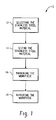
- FIG. 1 is a block diagram of the method in accordance with the present invention.
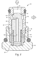
- FIG. 2 is a sectional view of a check valve assembly including components made in accordance with the present invention.
- FIG. 1 a block diagram of the steps of the method 10 in accordance with the present invention.
- the first step 12 in the process according to the present invention is the step of selecting a suitable stainless steel material for an intended hydraulic component .
- the preferred material employed in the present invention is a stainless steel material selected from the 400 grade or series, for example, an AISI ( The American Iron and Steel Institute) 400 series stainless steel material.
- the 400 series stainless steel material offers strength, heat and corrosion resistance, formability, as well as a pleasant aesthetic appearance and low maintenance.
- the 400 series stainless steel material is hardenable by heat treatment and available in a bar stock form.
- Some examples of a 400 series or grade stainless steel include, but are not limited to, AISI types 403, 405, 410, 414, 416, 420, 430, and 440. Chromium content ranges from a minimum of about 11% to about 16% on a weight percent basis and nickel content may range up to about 2%.
- martensitic stainless steel is a term well known in this industry and refers to a stainless steel material having chromium content ranging from about 12 to about 18% on a weight percent basis and a moderate carbon content, i.e., containing more than about 0.08% (wt. %) carbon. These types of steel are hardenable by heat treatment, for example, quenching and tempering like a plain carbon steel, and are suitable for use with the present invention.
- Representative types of stainless steel material suitable for use in the present invention have the following chemical compositions, as is known in the industry, with all of the values of the elements being provided on a weight percent basis (wt. %).
- Martensitic stainless steel materials are hardenable by heating above the crucial or transformation temperature, and then rapidly cooling in oil or air. Proper selection of grades and of primarily carbon and chromium content provides a wide range of "as quenched hardness" for a variety of applications.
- the martensitic stainless steel material offers maximum corrosion resistance in the hardenable condition and may be annealed for best cold working and/or machining characteristics.
- a type 416 stainless steel material is used which conforms to American Society of Testing Materials (ASTM) specifications A-276 or A-582, condition H or Y (annealed or not annealed), to obtain optimal core hardness. This core hardness is sufficient to accommodate nitriding after machining when nitriding is desired.
- nitriding is not a requirement of the present invention but may be desired for the hydraulic component or for specific locations on the hydraulic component, for example, the threaded male portions.
- the selected stainless steel material in the present invention preferably has a minimum hardness of about 26 HRC (Rockwell hardness value or equivalent unit of measure), and has preferably less than about 2% (wt. %) ferrites.
- the present invention is applicable to a pre-heat treated stainless steel that is capable of being machined in a hardened form.
- the preferred pre-heat treatment of type 416 SS material includes a heat treatment ranging from about 1700°-1750°F for approximately one hour followed by air cooling.
- the material undergoes double tempering at about 600°F for approximately two hours with air cooling between the tempering steps.
- the material In the annealed condition, the material has a hardness of about 222 BHN (Brinell hardness value).
- the resultant hardness after heat treatment is about 400 BHN.
- the next step 14 in the process 10 of the present invention is the sizing step.
- This step includes the step of providing the selected pre-heat treated stainless steel material in a desired size of bar stock form.
- a type 416 SS material is ordered as a rod with a diameter of about 1 ⁇ 2 inch and a length of about twelve feet.
- This size and shape can be loaded directly into a two-axis CNC lathe.
- the sizing step can optionally include cutting the bar stock to a predetermined size to allow for direct feeding into a lathe or similar unit.
- the machining step 16 in accordance with the present invention uses any conventional machining operation such as the two-axis CNC lathe to machine the hydraulic component in one setup or single machine loading or operation.
- the material is removed in multiple, single passes referred to as turning. Since the "turning" is conducted on a pre-heat treated hardened material, this step is referred to herein as "hard turning".
- machining as used herein is meant to include any machining operation including, but not limited to, milling, drilling, boring, reaming, grinding, polishing, and threading.
- the hydraulic component is removed from the machine, it is a completed part made to a precision finished dimension.
- the process uses indexable carbide cutting tools readily available in the market and typically already in use on these machines.
- the method of the present invention includes providing the stainless steel material at a slightly higher feed rate with a lower rpm (revolutions per minute) than a carbon steel material.
- the lubricants used for the turning operation are soluble water based coolants also commercially available in the market and known to those skilled in this art.
- Step 18 of the present invention optionally includes any post machining steps including, but not limited to, nitriding or heat treatments. Endurance tests conducted on the performance or life cycle of check valves did not indicate any significant affect of nitriding. Further testing on subsequent hydraulic components or portions thereof may reveal nitriding to be of some benefit to the performance or life cycle. Nitriding is done in a conventional manner well known in the industry.
- Check valve 20 is a device well known in this art. A brief explanation of its structure and operation will provide a better understanding of the present invention.
- Check valve 20 has a poppet valve 22 resiliently biased within a bore 24 of a cage 26.
- Cage 26 is threadably received within a retainer 28.
- a spring 30 surrounds a first cylindrical portion 32 of the poppet valve 22 and is retained thereon by one end of the spring 30 abutting a shoulder 34 of a second cylindrical portion 36 having a larger diameter than the diameter of the first cylindrical portion 32.
- the other end of spring 30 abuts the base 38 of the retainer 28 for biasing a poppet face 40 of the poppet valve 22 against a seat 42 of the cage 26.
- Cage 26 further includes ports 44, 46 fluidly communicating with a chamber 48 therein.
- Poppet valve 22 is typically biased in a closed position as shown in Fig. 2. Fluid flow in the direction of arrow A in port 44 exerts a fluid pressure greater than the biasing force of spring 30 to open the poppet valve 22. The fluid exits through chamber 48 and out port 46 in the direction of arrow B. When the fluid pressure entering port 44 is reduced to a point where the biasing force of spring 30 is greater than the fluid pressure, the poppet valve 22 moves to its closed position. A passage 50 through poppet valve 22 in fluid communication with chamber 48 utilizes fluid pressure to fluidly assist the biasing force of spring 30 for a sealing engagement of poppet face 40 against cage seat 42.
- the process 10 of the present invention was used to produce the following hydraulic components from the given materials. Their hardness values are given in Brinell units or Rockwell units of measurement. Only the cage 26 and poppet valve 22 were made of stainless steel material in these examples. The retainer 28 was made from a carbon steel.
- the outer diameter (O.D.) of poppet valve 22 was machined on the 2-axis CNC lathe in a finisher and roughing step that employed a SANDVIK, a registered trademark of Sandvik Aktiebolag Corporation, (cat. no. VNMG332-MM 2015 m15) turning tool with the lathe operating at about 600 sfm (surface feet per minute) and a feed rate of about 0.003 inches per revolution (ipr).
- the O.D. turning for the angle seat area employs a VALENITE (VLG-20262R) VL929 turning tool.
- VALENITE is a registered trademark of Valenite Inc.
- the lathe operates at approximately 90 rpm with a feed rate of 0.0015 ipr.
- Carbide drills having a C2 grade of carbide were employed for drilling the passage 50 in poppet valve 22. Initially a carbide center drill having a diameter of approximately 0.060 inch was used at a speed of about 1562 rpm with a feed rate of about 0.004 ipr. This was followed by a drill at a speed of about 3000 rpm and a feed rate of about 0.002 ipr.
- a 7 / 64 inch drill was used for the 90° angled portion of passage 50.
- the operating speed was about 3000 rpm with a feed rate of about 0.0015 ipr.
- a 3 / 64 inch ball endmill operating at about 4500 rpm was employed next with a feed rate of about 0.7 inch per minute.
- the cutoff tool was an ISCAR (DGN 3102J IC328) at about 2500 rpm with a feed rate of 0.002 ipr.
- ISCAR is a trademark of ISCAR Ltd.
- the power requirement is based on average unit power requirements of spindle drive motor corrected for approximately 80% spindle efficiency for turning using sharp tools. Units are in horsepower per cubic inch per minute. Part and material Used Material Hardness Cage Material 416 Stainless Steel 187 BHN Poppet material 410 Stainless Steel - Nitrided 222 BHN then (15n) Cage Material 410 Stainless Steel 222 BHN Poppet material 416 Stainless Steel - Not Nitrided 28 HRC Cage Material 416 Stainless Steel 28 HRC Poppet material 416 Stainless Steel - Nitrided 28 HRC then (15n) Cage Material 416 Stainless Steel 28 HRC Poppet material 416 Stainless Steel - Not Nitrided 28 HRC Cage Material 420 Stainless Steel 222 BHN Poppet material 420 Stainless Steel - Nitrided 222 BHN then (15n) Cage Material 410 Stainless Steel 222 BHN Poppet material 420 Stainless Steel - Not Nitrided 222 BHN then (15n) Cage Material
- the check valves were assembled and tested with a standard valve endurance test of at least 1,000,000 cycles (a cycle is the opening and closing of the check valve) to determine functional life and leakage of the valves.
- the tested valves had a rated pressure of about 5750 psi (pounds per square inch) with a flow rate of about 20 GPM (gallons per minute).
- the fluid employed was a Mobil DTE 24 oil heated to a temperature of 180 degrees F.
- Port 44 was the inlet port and port 46 the outlet port.
- Leakage was checked at port 44 with a pressure of about 500, about 3000, and about 5200 psi at port 46.
- An on-off cycle ranged from about 0.3 to 0.5 second . Valve leakage was checked approximately every 250,000 cycles.
- the normal leakage rate for materials currently used such as the carbon steels for a fluid having the same viscosity is about 0 to 5 drops per minute when new, and about 0 to 15 drops per minute after 1,000,000 cycles. Performance of the valve deteriorates as a function of time. Since the leakage rate for the hydraulic components made in accordance with the present invention did not change and remained fairly constant over a period of time, it appears that the selected stainless steel material is a work hardening material.
- the poppet valve 22 used in check valve 20 has finish and roundness specification values of 16 RMS finish and roundness of 0.00005 inch. All of the poppet valves produced in accordance with the present invention had a roundness ranging from about 0.00002 to about 0.00003 inch during the turning operation with a surface finish of about 30-43 RMS. All values are well within the specifications.
Landscapes
- Chemical & Material Sciences (AREA)
- Engineering & Computer Science (AREA)
- Mechanical Engineering (AREA)
- Materials Engineering (AREA)
- Metallurgy (AREA)
- Organic Chemistry (AREA)
- Physics & Mathematics (AREA)
- Crystallography & Structural Chemistry (AREA)
- Thermal Sciences (AREA)
- Chemical Kinetics & Catalysis (AREA)
- Fluid Mechanics (AREA)
- General Engineering & Computer Science (AREA)
- Heat Treatment Of Articles (AREA)
- Safety Valves (AREA)
- Lift Valve (AREA)
Abstract
Description
Representative types of stainless steel material suitable for use in the present invention have the following chemical compositions, as is known in the industry, with all of the values of the elements being provided on a weight percent basis (wt. %).
| 416 | 410/403 | 420 | |
| C | 0.14 | 0.130 | 0.34 |
| Si | 0.34 | 0.310 | 0.43 |
| Mn | 0.94 | 0.420 | 0.41 |
| P | 0.028 | 0.016 | 0.02 |
| S | 0.280 | 0.005 | 0.002 |
| Ni | 0.40 | 0.260 | 0.24 |
| Cr | 12.83 | 11.940 | 12.34 |
| Mo | 0.06 | 0.190 | 0.07 |
| Cu | 0.04 | 0.150 | 0.07 |
| N | 0.0335 | 0.051 | ------- |
| Mo + Zr | 0.062 | --------- | ------- |
| Co | -------- | 0.050 | 0.03 |
| Al | -------- | 0.0100 | 0.003 |
| Material | Hardness | Power Requirement |
| Aluminum alloys Steels | 30-150 BHN | 0.25 |
| - plain carbon | 35-40 HRC | 1.4 |
| - alloy | 40-50 HRC | 1.5 |
| - tool | 50-55 HRC | 2.0 |
| Stainless steel (ferritic, austenitic, martensitic) | 30-45 HRC | 1.4 |
| Stainless steel | 150-450 BHN | 1.2 |
| Part and material Used | Material Hardness |
| Cage Material 416 Stainless Steel | 187 BHN |
| Poppet material 410 Stainless Steel - Nitrided | 222 BHN then (15n) |
| Cage Material 410 Stainless Steel | 222 BHN |
| Poppet material 416 Stainless Steel - | 28 HRC |
| Cage Material 416 | 28 HRC |
| Poppet material 416 Stainless Steel - | 28 HRC then (15n) |
| Cage Material 416 | 28 HRC |
| Poppet material 416 Stainless Steel - | 28 HRC |
| Cage Material 420 Stainless Steel | 222 BHN |
| Poppet material 420 Stainless Steel - Nitrided | 222 BHN then (15n) |
| Cage Material 410 Stainless Steel | 222 BHN |
| Poppet material 420 Stainless Steel - Not Nitrided | 222 BHN |
Claims (16)
- In a method for making a hydraulic component, the improvement comprises the step of hard turning a pre-heat treated stainless steel material to a precision finished dimension.
- A method as recited in claim 1, wherein the pre-heat treated stainless steel material comprises a 400 series stainless steel material.
- A hydraulic component made in accordance with the method of claim 1.
- A stainless steel hydraulic component, wherein said hydraulic component is a hard turned, pre-heat treated stainless steel hydraulic component.
- A stainless steel hydraulic component as recited in claim 4, wherein said stainless steel is a 400 series stainless steel.
- A stainless steel hydraulic component as recited in claim 4, wherein said stainless steel is a type 410 stainless steel.
- A stainless steel hydraulic component as recited in claim 4, wherein said stainless steel is a type 416 stainless steel.
- A stainless steel hydraulic component as recited in claim 4, wherein said stainless steel is a type 420 stainless steel.
- A method for making a stainless steel hydraulic component, comprising the steps of:selecting a pre-heat treated stainless steel material having a predetermined minimum hardness value;providing the selected pre-heat treated stainless steel material in bar stock form; andmachining a hydraulic component from the pre-heat treated stainless steel material to a finished dimension in a single machining loading.
- A method as recited in claim 9, wherein said pre-heat treated stainless steel material further includes a predetermined maximum ferrite content.
- A method as recited in claim 10, wherein said predetermined maximum ferrite content is equal to or less than about 2% (wt. %).
- A method as recited in claim 9, wherein said pre-heat treated stainless steel material has a minimum hardness value of about 26 HRC.
- A method as recited in claim 9, further comprising the step of nitriding at least a portion of the hydraulic component after the machining step.
- A stainless steel hydraulic component manufactured in accordance with method set forth in claim 9.
- A stainless steel hydraulic valve component, wherein said stainless steel hydraulic valve component comprises a hard turned pre-heat treated stainless steel hydraulic valve component that work hardens over a period of time.
- A stainless steel hydraulic valve component as recited in claim 15, wherein said stainless steel hydraulic valve component is machined in a single machining operation.
Applications Claiming Priority (2)
| Application Number | Priority Date | Filing Date | Title |
|---|---|---|---|
| US735962 | 2000-12-13 | ||
| US09/735,962 US6589363B2 (en) | 2000-12-13 | 2000-12-13 | Method for making heat treated stainless hydraulic components |
Publications (2)
| Publication Number | Publication Date |
|---|---|
| EP1215290A2 true EP1215290A2 (en) | 2002-06-19 |
| EP1215290A3 EP1215290A3 (en) | 2005-02-02 |
Family
ID=24957903
Family Applications (1)
| Application Number | Title | Priority Date | Filing Date |
|---|---|---|---|
| EP01129447A Withdrawn EP1215290A3 (en) | 2000-12-13 | 2001-12-10 | Heat treated stainless steel hydraulic components and method for making same |
Country Status (3)
| Country | Link |
|---|---|
| US (1) | US6589363B2 (en) |
| EP (1) | EP1215290A3 (en) |
| JP (1) | JP2002317877A (en) |
Families Citing this family (5)
| Publication number | Priority date | Publication date | Assignee | Title |
|---|---|---|---|---|
| US7169238B2 (en) * | 2003-12-22 | 2007-01-30 | Caterpillar Inc | Carbide method and article for hard finishing resulting in improved wear resistance |
| US8153195B2 (en) * | 2006-09-09 | 2012-04-10 | Electronics For Imaging, Inc. | Dot size controlling primer coating for radiation curable ink jet inks |
| CN103527283B (en) * | 2013-10-18 | 2016-05-18 | 无锡动力工程股份有限公司 | Pressure regulation assembly |
| CN113175522A (en) * | 2021-06-03 | 2021-07-27 | 内蒙古霍煤鸿骏铝电有限责任公司扎哈淖尔分公司 | Control valve group device for wind turbine generator gearbox lubricating system |
| CN115044826B (en) * | 2022-05-07 | 2023-09-15 | 广西柳州钢铁集团有限公司 | 410 ferritic stainless steel |
Family Cites Families (9)
| Publication number | Priority date | Publication date | Assignee | Title |
|---|---|---|---|---|
| CA1223140A (en) * | 1984-06-28 | 1987-06-23 | Raynald Simoneau | Austenitic cobalt stainless steel exhibiting ultra high resistance to erosive cavitation |
| JPS63212452A (en) * | 1987-02-27 | 1988-09-05 | Toyoda Mach Works Ltd | Beveling method for rotary servo valve |
| DE4101671A1 (en) * | 1991-01-22 | 1992-07-23 | Zahnradfabrik Friedrichshafen | Production of control slots in slide valve core piece - uses profiled grinding wheel to grind slot from solid in one operation |
| US5257453A (en) * | 1991-07-31 | 1993-11-02 | Trw Inc. | Process for making exhaust valves |
| US5513671A (en) | 1994-07-13 | 1996-05-07 | Schwing America, Inc. | Hydraulically controlled water spool valve |
| US5802937A (en) | 1995-07-26 | 1998-09-08 | The Regents Of The University Of Calif. | Smart tool holder |
| US5672218A (en) * | 1996-06-24 | 1997-09-30 | Slater Steels Corporation | Method of straightening metal bars having extremely low levels of residual stress after straightening operations are completed |
| DE19840738C5 (en) * | 1998-09-07 | 2007-03-08 | Fraunhofer-Gesellschaft zur Förderung der angewandten Forschung e.V. | Method for semifinishing or finish machining of surfaces of rotationally symmetric sections of workpieces made of hard or hardened material and rotary tool for carrying out the method |
| US6440237B1 (en) * | 2000-05-23 | 2002-08-27 | Delphi Technologies, Inc. | Process for forming cold formed high-load bearing steel parts |
-
2000
- 2000-12-13 US US09/735,962 patent/US6589363B2/en not_active Expired - Fee Related
-
2001
- 2001-12-10 EP EP01129447A patent/EP1215290A3/en not_active Withdrawn
- 2001-12-10 JP JP2001375637A patent/JP2002317877A/en active Pending
Also Published As
| Publication number | Publication date |
|---|---|
| US6589363B2 (en) | 2003-07-08 |
| US20020112795A1 (en) | 2002-08-22 |
| JP2002317877A (en) | 2002-10-31 |
| EP1215290A3 (en) | 2005-02-02 |
Similar Documents
| Publication | Publication Date | Title |
|---|---|---|
| Akıncıoğlu et al. | The effects of cryogenic-treated carbide tools on tool wear and surface roughness of turning of Hastelloy C22 based on Taguchi method | |
| KR100216877B1 (en) | Rolling bearing | |
| Fichtl | Boronizing and its practical applications | |
| AU2014216315B2 (en) | Hard weld overlays resistant to re-heat cracking | |
| Bayer et al. | High-speed tool steels | |
| EP1614762B1 (en) | Wear resistant alloy for valve seat insert | |
| Isakov | Cutting Data for turning of steel | |
| SE526481C2 (en) | Surface hardened stainless steel with improved abrasion resistance and low static friction | |
| US5160553A (en) | Cold-worked steel of high compressive strength and articles made thereof | |
| US6589363B2 (en) | Method for making heat treated stainless hydraulic components | |
| Dossett et al. | Heat Treating of Irons and Steels | |
| SE526501C2 (en) | Method of surface modifying a precipitation-hardened stainless steel | |
| Jacobson | Surface integrity of hard-turned M50 steel | |
| US20060032334A1 (en) | Method for manufacturing extrusion die tools | |
| CN1070929C (en) | The application of a kind of steel in the tool holder | |
| Saï et al. | Influence of finishing by burnishing on surface characteristics | |
| GB2315775A (en) | Rolling Bearing | |
| CA2171084A1 (en) | Free-machining martensitic stainless steel | |
| US4471899A (en) | Method for fabricating hollow cylinders of machines | |
| Lube et al. | Extending the life of piercing plugs | |
| Toirov et al. | Applications of HSS alloys for the production of planetary core cutting heads for tapping holes | |
| Balogun et al. | Characterization of Chip and Burr Formation at High Speed Machining of Nitronic 33 Steel Alloy | |
| JP2706940B2 (en) | Manufacturing method of non-heat treated steel for nitriding | |
| JPS62136555A (en) | Steel wire for wear and corrosion resistant parts having high fatigue strength | |
| Ahmed | Machinability of Stainless Steels |
Legal Events
| Date | Code | Title | Description |
|---|---|---|---|
| PUAI | Public reference made under article 153(3) epc to a published international application that has entered the european phase |
Free format text: ORIGINAL CODE: 0009012 |
|
| AK | Designated contracting states |
Kind code of ref document: A2 Designated state(s): AT BE CH CY DE DK ES FI FR GB GR IE IT LI LU MC NL PT SE TR |
|
| AX | Request for extension of the european patent |
Free format text: AL;LT;LV;MK;RO;SI |
|
| PUAL | Search report despatched |
Free format text: ORIGINAL CODE: 0009013 |
|
| AK | Designated contracting states |
Kind code of ref document: A3 Designated state(s): AT BE CH CY DE DK ES FI FR GB GR IE IT LI LU MC NL PT SE TR |
|
| AX | Request for extension of the european patent |
Extension state: AL LT LV MK RO SI |
|
| 17P | Request for examination filed |
Effective date: 20050519 |
|
| AKX | Designation fees paid |
Designated state(s): DE FR GB IT |
|
| STAA | Information on the status of an ep patent application or granted ep patent |
Free format text: STATUS: THE APPLICATION IS DEEMED TO BE WITHDRAWN |
|
| 18D | Application deemed to be withdrawn |
Effective date: 20080701 |