EP1215123A1 - Device for controlling the position of packages on a production line - Google Patents
Device for controlling the position of packages on a production line Download PDFInfo
- Publication number
- EP1215123A1 EP1215123A1 EP00830804A EP00830804A EP1215123A1 EP 1215123 A1 EP1215123 A1 EP 1215123A1 EP 00830804 A EP00830804 A EP 00830804A EP 00830804 A EP00830804 A EP 00830804A EP 1215123 A1 EP1215123 A1 EP 1215123A1
- Authority
- EP
- European Patent Office
- Prior art keywords
- packages
- supporting
- position reference
- conveying
- unit
- Prior art date
- Legal status (The legal status is an assumption and is not a legal conclusion. Google has not performed a legal analysis and makes no representation as to the accuracy of the status listed.)
- Withdrawn
Links
- 238000004519 manufacturing process Methods 0.000 title claims description 6
- 230000003287 optical effect Effects 0.000 claims abstract description 16
- 235000013305 food Nutrition 0.000 claims abstract description 13
- 238000012545 processing Methods 0.000 claims description 6
- 238000011144 upstream manufacturing Methods 0.000 claims description 3
- 239000005022 packaging material Substances 0.000 description 11
- 239000000463 material Substances 0.000 description 10
- 238000010438 heat treatment Methods 0.000 description 6
- 239000004033 plastic Substances 0.000 description 5
- 229920003023 plastic Polymers 0.000 description 5
- 238000007789 sealing Methods 0.000 description 5
- 238000001514 detection method Methods 0.000 description 4
- 238000004806 packaging method and process Methods 0.000 description 4
- 230000004888 barrier function Effects 0.000 description 3
- 239000004698 Polyethylene Substances 0.000 description 2
- XAGFODPZIPBFFR-UHFFFAOYSA-N aluminium Chemical compound [Al] XAGFODPZIPBFFR-UHFFFAOYSA-N 0.000 description 2
- 229910052782 aluminium Inorganic materials 0.000 description 2
- 239000004411 aluminium Substances 0.000 description 2
- 238000010586 diagram Methods 0.000 description 2
- 230000002452 interceptive effect Effects 0.000 description 2
- -1 polyethylene Polymers 0.000 description 2
- 229920000573 polyethylene Polymers 0.000 description 2
- 238000012546 transfer Methods 0.000 description 2
- MHAJPDPJQMAIIY-UHFFFAOYSA-N Hydrogen peroxide Chemical compound OO MHAJPDPJQMAIIY-UHFFFAOYSA-N 0.000 description 1
- 235000007688 Lycopersicon esculentum Nutrition 0.000 description 1
- 240000003768 Solanum lycopersicum Species 0.000 description 1
- 238000009455 aseptic packaging Methods 0.000 description 1
- 238000012937 correction Methods 0.000 description 1
- 238000013461 design Methods 0.000 description 1
- 239000002657 fibrous material Substances 0.000 description 1
- 235000015203 fruit juice Nutrition 0.000 description 1
- 238000003780 insertion Methods 0.000 description 1
- 230000037431 insertion Effects 0.000 description 1
- 239000007788 liquid Substances 0.000 description 1
- 235000020191 long-life milk Nutrition 0.000 description 1
- 238000012423 maintenance Methods 0.000 description 1
- 235000013336 milk Nutrition 0.000 description 1
- 239000008267 milk Substances 0.000 description 1
- 210000004080 milk Anatomy 0.000 description 1
- 238000003909 pattern recognition Methods 0.000 description 1
- 230000002093 peripheral effect Effects 0.000 description 1
- 235000015067 sauces Nutrition 0.000 description 1
- 230000035939 shock Effects 0.000 description 1
- 230000003068 static effect Effects 0.000 description 1
- 230000001954 sterilising effect Effects 0.000 description 1
- 238000004659 sterilization and disinfection Methods 0.000 description 1
- 239000003206 sterilizing agent Substances 0.000 description 1
- 239000000126 substance Substances 0.000 description 1
- 230000001360 synchronised effect Effects 0.000 description 1
- 235000014101 wine Nutrition 0.000 description 1
Images


Classifications
-
- B—PERFORMING OPERATIONS; TRANSPORTING
- B65—CONVEYING; PACKING; STORING; HANDLING THIN OR FILAMENTARY MATERIAL
- B65B—MACHINES, APPARATUS OR DEVICES FOR, OR METHODS OF, PACKAGING ARTICLES OR MATERIALS; UNPACKING
- B65B61/00—Auxiliary devices, not otherwise provided for, for operating on sheets, blanks, webs, binding material, containers or packages
- B65B61/18—Auxiliary devices, not otherwise provided for, for operating on sheets, blanks, webs, binding material, containers or packages for making package-opening or unpacking elements
- B65B61/186—Auxiliary devices, not otherwise provided for, for operating on sheets, blanks, webs, binding material, containers or packages for making package-opening or unpacking elements by applying or incorporating rigid fittings, e.g. discharge spouts
-
- B—PERFORMING OPERATIONS; TRANSPORTING
- B31—MAKING ARTICLES OF PAPER, CARDBOARD OR MATERIAL WORKED IN A MANNER ANALOGOUS TO PAPER; WORKING PAPER, CARDBOARD OR MATERIAL WORKED IN A MANNER ANALOGOUS TO PAPER
- B31B—MAKING CONTAINERS OF PAPER, CARDBOARD OR MATERIAL WORKED IN A MANNER ANALOGOUS TO PAPER
- B31B50/00—Making rigid or semi-rigid containers, e.g. boxes or cartons
- B31B50/74—Auxiliary operations
- B31B50/81—Forming or attaching accessories, e.g. opening devices, closures or tear strings
- B31B50/84—Forming or attaching means for filling or dispensing contents, e.g. valves or spouts
-
- B—PERFORMING OPERATIONS; TRANSPORTING
- B65—CONVEYING; PACKING; STORING; HANDLING THIN OR FILAMENTARY MATERIAL
- B65B—MACHINES, APPARATUS OR DEVICES FOR, OR METHODS OF, PACKAGING ARTICLES OR MATERIALS; UNPACKING
- B65B43/00—Forming, feeding, opening or setting-up containers or receptacles in association with packaging
- B65B43/42—Feeding or positioning bags, boxes, or cartons in the distended, opened, or set-up state; Feeding preformed rigid containers, e.g. tins, capsules, glass tubes, glasses, to the packaging position; Locating containers or receptacles at the filling position; Supporting containers or receptacles during the filling operation
- B65B43/52—Feeding or positioning bags, boxes, or cartons in the distended, opened, or set-up state; Feeding preformed rigid containers, e.g. tins, capsules, glass tubes, glasses, to the packaging position; Locating containers or receptacles at the filling position; Supporting containers or receptacles during the filling operation using roller-ways or endless conveyors
-
- B—PERFORMING OPERATIONS; TRANSPORTING
- B65—CONVEYING; PACKING; STORING; HANDLING THIN OR FILAMENTARY MATERIAL
- B65B—MACHINES, APPARATUS OR DEVICES FOR, OR METHODS OF, PACKAGING ARTICLES OR MATERIALS; UNPACKING
- B65B59/00—Arrangements to enable machines to handle articles of different sizes, to produce packages of different sizes, to vary the contents of packages, to handle different types of packaging material, or to give access for cleaning or maintenance purposes
- B65B59/005—Adjustable conveying means
-
- B—PERFORMING OPERATIONS; TRANSPORTING
- B31—MAKING ARTICLES OF PAPER, CARDBOARD OR MATERIAL WORKED IN A MANNER ANALOGOUS TO PAPER; WORKING PAPER, CARDBOARD OR MATERIAL WORKED IN A MANNER ANALOGOUS TO PAPER
- B31B—MAKING CONTAINERS OF PAPER, CARDBOARD OR MATERIAL WORKED IN A MANNER ANALOGOUS TO PAPER
- B31B50/00—Making rigid or semi-rigid containers, e.g. boxes or cartons
- B31B50/006—Controlling; Regulating; Measuring; Improving safety
-
- B—PERFORMING OPERATIONS; TRANSPORTING
- B65—CONVEYING; PACKING; STORING; HANDLING THIN OR FILAMENTARY MATERIAL
- B65B—MACHINES, APPARATUS OR DEVICES FOR, OR METHODS OF, PACKAGING ARTICLES OR MATERIALS; UNPACKING
- B65B55/00—Preserving, protecting or purifying packages or package contents in association with packaging
- B65B55/02—Sterilising, e.g. of complete packages
- B65B55/04—Sterilising wrappers or receptacles prior to, or during, packaging
- B65B55/10—Sterilising wrappers or receptacles prior to, or during, packaging by liquids or gases
- B65B55/103—Sterilising flat or tubular webs
Definitions
- the operating head is maintained in the rest position by springs 57; and the movement of operating head 55 is controlled by a fixed cam (not shown) extending along path P at application station 11 and over rotary table 7, and which cooperates with a cam follower 58 fixed to operating head 55.
Landscapes
- Engineering & Computer Science (AREA)
- Mechanical Engineering (AREA)
- Microelectronics & Electronic Packaging (AREA)
- Auxiliary Devices For And Details Of Packaging Control (AREA)
Abstract
Description
- The present invention relates to a device for controlling the position of packages of pourable food products on a production line on which the packages are conveyed successively.
- As is known, many pourable food products, such as fruit juice, UHT (ultra-high-temperature processed) milk, wine, tomato sauce, etc., are sold in packages made of sterilized packaging material.
- A typical example of such a package is the parallelepiped-shaped package for liquid or pourable food products known as Tetra Brik Aseptic (registered trademark), which is formed by folding and sealing a web of laminated packaging material. The packaging material has a multilayer structure comprising a layer of fibrous material, e.g. paper, covered on both sides with layers of heat-seal plastic material, e.g. polyethylene, and, in the case of aseptic packages for long-storage products, such as UHT milk, also comprises a layer of oxygen-barrier material defined, for example, by an aluminium film, which is superimposed on a layer of heat-seal plastic material and is in turn covered with another layer of heat-seal plastic material eventually defining the inner face of the package contacting the food product.
- As is known, such packages are made on fully automatic packaging machines, on which a continuous tube is formed from the web-fed packaging material; the web of packaging material is sterilized on the packaging machine itself, e.g. by applying a chemical sterilizing agent, such as a hydrogen peroxide solution, which, after sterilization, is removed, e.g. vaporized by heating, from the surfaces of the packaging material; and the web of packaging material so sterilized is maintained in a closed sterile environment, and is folded and sealed longitudinally to form a vertical tube.
- The tube is filled with the sterilized or sterile-processed food product, and is sealed and cut at equally spaced cross sections to form pillow packs, which are then folded mechanically to form the finished, e.g. substantially parallelepiped-shaped, packages.
- Alternatively, the packaging material may be cut into blanks, which are formed into packages on forming spindles, and the resulting packages are filled with the food product and sealed. One example of such a package is the so-called "gable-top" package commonly known by the trade name Tetra Rex (registered trademark).
- Once formed, packages of the above type may undergo further processing, such as the application of a closable opening device, to which reference is made herein purely by way of example.
- The most commonly used opening devices comprise a frame defining an opening and fitted about a pierceable or removable portion of the top wall of the package; and a cap hinged or screwed to the frame and which can be removed to open the package. Other, e.g. slidable, opening devices are also known to be used.
- The pierceable portion of the package may be defined, for example, by a so-called "prelaminated" hole, i.e. a hole formed in the fibrous layer of the packaging material before the fibrous layer is joined to the barrier layer, which is thus whole and closes the hole to ensure hermetic, aseptic sealing, while at the same time being easily pierced.
- In the case of aseptic packaging machines, the opening devices described are normally fitted continuously straight on to the formed packages on on-line application units downstream from the packaging machine.
- Known units for applying opening devices substantially comprise a chain conveyor for feeding the packages successively along a normally straight transfer path; first heating means for locally heating the packages at the pierceable portions; second heating means for heating the opening devices; and application means activated along the transfer path to apply the opening devices on to the packages.
- On known conveyors, the position of the packages on the conveyor is normally determined by the lateral walls of the packages mechanically contacting respective movable push walls and fixed guide surfaces on the conveyor. The accuracy with which the packages are positioned with respect to the application means, however, is affected by various factors, such as conveyor tolerances and the intrinsically changing shape of the package, which is made of flexible material, as opposed to being rigid.
- Heat sealing the opening devices, especially in the case of packages with prelaminated holes, on the other hand, calls for extremely accurate positioning of the packages with respect to the application means. Applying the opening device in the wrong position may result in various problems, such as poor adhesion to the package and malfunctioning of the opening device itself, which in turn may result in difficulty in opening the package, product leakage, or splashing when the product is poured out.
- A demand therefore exists in the industry for precise on-line position control of the packages, to ensure application of the opening devices and any other auxiliary processing of the packages are performed to a high degree of precision.
- It is an object of the present invention to provide a reliable, low-cost device for controlling the on-line position of packages of pourable food products, while at the same time permitting high production speed.
- According to the present invention, there is provided a device for controlling the position of packages of pourable food products on a production line on which the packages are conveyed successively and subjected to an operation performed by an operating head; said packages having optically detectable first position reference means; the device being characterized by comprising:
- a number of supporting and conveying devices for supporting and conveying said packages;
- optically detectable second position reference means associated with each said supporting and conveying device and defining, for each said supporting and conveying device, a position reference system integral with the supporting and conveying device;
- optical sensing means having such a viewing range as to simultaneously detect said first and said second position reference means;
- a control unit having processing means for determining the position of said first position reference means with respect to said position reference system defined by said second position reference means; and
- adjusting means for adjusting the relative position of each of said packages with respect to said operating head, and controlled by said control unit in response to a position error of said first position reference means within said position reference system defined by said second position reference means.
-
- According to the present invention, the position of each package is therefore adjusted individually with respect to the operating head by optical detection, thus enabling the relative position of the package to be adjusted accurately with no interference factors, such as deformation of the package itself.
- Moreover, optical detection is performed with respect to a reference system integral with the respective supporting and conveying device, as opposed to an absolute reference system, thus enabling accurate detection at any time and regardless of how accurately the sensor is positioned. As a result, high-cost, high-precision-timing control systems are not required, even at high production speeds; and, providing the first and second position reference means remain within the viewing range of the optical sensor, detection precision remains constant, even in the event of minor static or dynamic variations, e.g. due to shock or vibration, in the position of the sensor. The device is therefore highly reliable and calls for very little maintenance.
- The invention is conveniently used on a unit for applying opening devices to respective packages, in particular packages comprising a prelaminated hole, which is used as an optically detectable position reference element.
- According to a further aspect of the present invention, the opening device application unit is a rotary type featuring a rotary table to which the package supporting and conveying devices are fixed rigidly. This provides for further improving precision as compared with known linear application units featuring chain conveyors, which are invariably affected by inevitable slack on the chain.
- A preferred, non-limiting embodiment of the present invention will be described by way of example with reference to the accompanying drawings, in which:
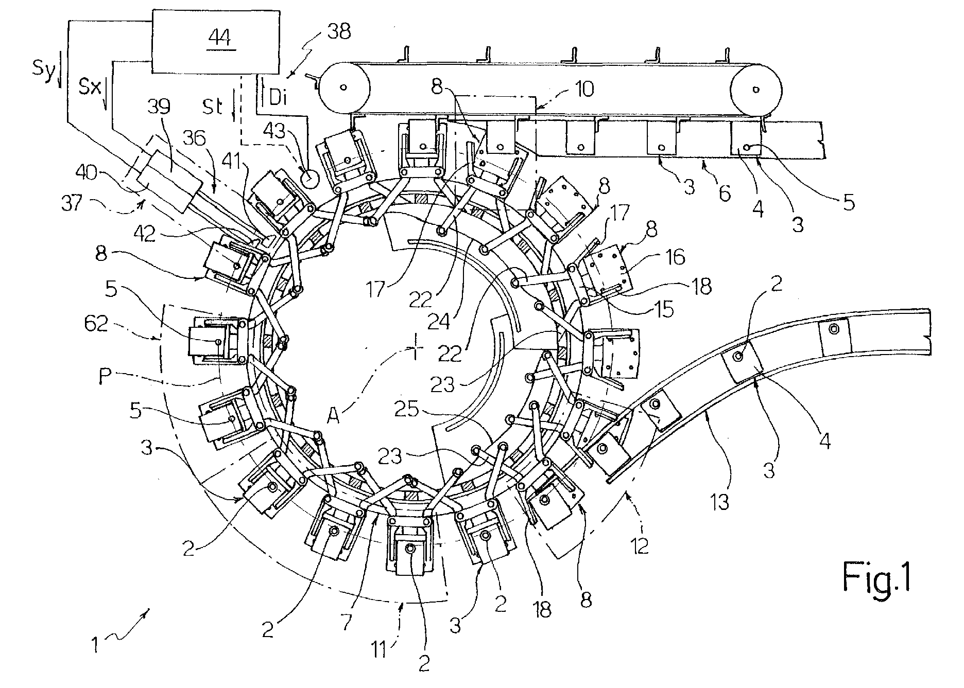
- Figure 1 shows a schematic plan view of a unit for applying opening devices to packages of pourable food products and featuring a package position control device in accordance with the present invention;
- Figure 2 shows a view in perspective of a detail of the control device according to the invention;
- Figure 3 shows, schematically, an image picked up by an optical sensor forming part of the control device;
- Figure 4 shows a partial view in perspective of the Figure 1 unit;
- Figure 5 shows a block diagram of a sequence of operations performed by a control unit of the device according to the invention.
-
-
Number 1 in Figure 1 indicates as a whole a unit for applyingopening devices 2 toaseptic packages 3 of pourable food products. -
Packages 3 are made on a packaging unit (not shown) from a web of sheet packaging material comprising a layer of paper material covered on both sides with layers of heat-seal plastic material, e.g. polyethylene; and a layer of barrier material, e.g. aluminium, located on the inside of the paper material layer and in turn covered on the inside with another layer of plastic material. - A
top face 4 of each ofpackages 3, which, in the example shown are substantially parallelepiped-shaped, has apierceable portion 5 conveniently defined by a so-called "prelaminated" hole, i.e. a hole formed in the paper layer of the packaging material before the paper layer is joined to the barrier layer, which thus closes the hole to ensure hermetic, aseptic sealing, while at the same time being easily pierced. -
Unit 1 comprises a rotary table 7, of axis A, rotated about its axis at constant speed by drive means not shown. Rotary table 7 supports a number of supporting and conveyingdevices 8 for supporting and conveyingpackages 3, and which are fixed in equally spaced manner to, and project radially from, a substantially cylindrical peripheral lateral wall 9 of rotary table 7 (Figure 4). -
Devices 8 receiverespective packages 3 from a known input conveyor 6 tangent to rotary table 7 at asupply station 10 and for conveyingpackages 3 in equally spaced manner and at a constant speed equal to the linear speed ofdevices 8. Rotating together with rotary table 7,devices 8feed packages 3 along a circular path P through an application station 11 for applyingopening devices 2 and up to anunloading station 12 wherepackages 3 are removed by anoutput conveyor 13. - More specifically, each device 8 (Figures 2 and 4) comprises a vertical wall or
back 15 fixed to wall 9 of rotary table 7; abase 16 on which arespective package 3 rests; and two lateral retainingmembers vertical wall 15 and loaded byrespective springs 19 so as to cooperate with respective lateral faces ofpackage 3 and keep the package steady onbase 16 throughout the time it remains on rotary table 7. -
Members respective package 3 along path P, haverespective control arms openings 19 in wall 9, and which interact with respectivefixed cams stations -
Cam 24 acts onarms 22 to produce a rotary opening movement ofmembers 17, i.e. away from thecorresponding members 18, and so permit insertion ofpackages 3 insiderespective devices 8 without interfering withmembers 17. Similarly,cam 25 acts onarms 23 to produce a rotary opening movement ofmembers 18 at unloadingstation 12 and so permit withdrawal ofpackages 3 without interfering with members 18 (Figure 1). -
Base 16 of each device 8 (Figure 4) substantially comprises a supportingplate 30 connected rigidly to a bottom edge of, and projecting from, wall 9 of rotary table 7; and amovable plate 31 on top of supportingplate 30, and thetop face 32 of which defines a horizontal supporting surface for arespective package 3.Movable plate 31 is connected toplate 30 with a certain amount of freedom to move in both a tangential direction X and a radial direction Y with respect to rotary table 7, and can be adjusted in position with respect to supportingplate 30 and in said directions by means of a mechanism 33 - not described in detail by not forming part of the present invention - housed betweenplates lever 34 to adjust the X position, and by alever 35 to adjust the Y position.Levers base 16, are hinged to supportingplate 30, and are activated by an adjustingdevice 36 located along path P, at an adjustingstation 37 betweensupply station 10 and station 11 for applyingopening devices 2, and forming part of adevice 38 for controlling the position ofpackages 3. - Device 38 (Figure 1) comprises two
servomotors respective cams 41, 42 designed to interact withlevers device 8 traveling through adjustingstation 37; for which purpose, levers 34, 35 comprise respectivecam follower rollers -
Device 38 comprises an optical sensor 43 - conveniently a video camera - located over path P betweensupply station 10 and adjustingstation 37; and acontrol unit 44 connected tooptical sensor 43 and toservomotors optical sensor 43. - Control unit 44 - which may be defined by the main, e.g. PLC, control unit of unit 1 - generates a trigger signal St for enabling
optical sensor 43, and which is conveniently defined by a succession of pulses synchronized with the travel of eachdevice 8 within the viewing range ofoptical sensor 43. - More specifically, and as shown in Figure 3, the viewing range of
optical sensor 43 is such as to simultaneously detectprelaminated hole 5, andreference marks 46 located in a fixed position ondevice 8 and defining areference system 45 by which to define the position of prelaminatedhole 5. In the example shown, the reference marks are defined by twocircular marks plate 47 fixed rigidly towall 15 ofdevice 8, and aligned with each other in a tangential (X) direction with respect to rotary table 7. Marks 46a, 46b therefore define a point O, e.g. coincident with the center ofmark 46a and defining the origin of the cartesian reference system; and an axis (X) of the cartesian reference system, defined by the line joining the centers ofmarks -
Unit 1 also comprises a number of application devices 50 (Figure 4), each secured to rotary table 7 over a respective supportingdevice 8, and which, not forming part of the invention, are only described as required for a clear understanding of the invention. Very briefly, eachapplication device 50 comprises avertical guide 54 secured to the rotary table; and anoperating head 55 havingjaws 56 for gripping anopening device 2, and which is movable alongguide 54 between a raised rest position (Figure 4) and a lowered work position in whichopening device 2 is pressed ontopackage 3 at prelaminatedhole 5. The operating head is maintained in the rest position bysprings 57; and the movement ofoperating head 55 is controlled by a fixed cam (not shown) extending along path P at application station 11 and over rotary table 7, and which cooperates with acam follower 58 fixed to operatinghead 55. - By means of a conventional device not shown, the opening devices are conveniently supplied successively to
unit 1 atsupply station 10, where they are picked up byjaws 56.Jaws 56 are opened and closed by a pneumatic actuator (not shown) housed inoperating head 55 and activated by a mechanically controlledvalve 60, acontrol roller 61 of which interacts with a fixed cam (not shown) coaxial with rotary table 7, so as to close the jaws atstation 10 as soon asopening device 2 is supplied, and open the jaws oncedevice 2 is applied torespective package 3. -
Opening devices 2 are conveniently applied by heat sealing; for which purpose,packages 3 andopening devices 2 are first heated in known manner not described, e.g. by means of hot-air jets, at aheating station 62 immediately upstream from application station 11. - Operation of
device 38 for controlling the position ofpackages 3 onunit 1 will now be described with reference to the Figure 5 diagram, which shows the sequence of operations performed bycontrol unit 44 to adjust the position of eachpackage 3; which operations are obviously performed cyclically and in time with the rotation of table 7, i.e. with a period equal to the time taken by the table to rotate through the angle between twoconsecutive devices 8. - A
start block 64 is followed by ablock 65 wherecontrol unit 44 generates a trigger pulse St to enable acquisition of the image byoptical sensor 43, and which is followed by ablock 66 in which data Di fromsensor 43 is acquired. -
Block 66 goes on to animage processing block 67, which, on the basis of conventional pattern recognition algorithms not described in detail, determines the centers ofmarks block 67a) defining the local coordinate system (origin O and X axis), and the center C of prelaminated hole 5 (block 67b). - The
next block 68 calculates the hole center C coordinates within the local coordinate system defined bymarks 46, and then goes on to ablock 69, which compares the coordinates with respective theoretical reference values relative to the theoretical or design position ofprelaminated hole 5, and calculates respective error values ΔX, ΔY. - In response to values ΔX, ΔY, the
next block 70 generates signals Sx,Sy controlling servomotors cams 41, 42 of adjustingdevice 36 to a given correction position to correct the position error ofprelaminated hole 5. More specifically, asdevice 8 travels through adjustingstation 37,cam followers levers respective cams 41, 42, and levers 34, 35 rotate to shiftmovable plate 31 ofdevice 8 by a quantity -ΔX in direction X and by a quantity -ΔY in direction Y, and so ensureprelaminated hole 5 is positioned correctly with respect torelative application device 50. - When
device 8 reaches station 11, therespective opening device 2 is applied byapplication device 50 perfectly aligned withprelaminated hole 5. - Clearly, changes may be made to
unit 1 andcontrol device 38 as described herein without, however, departing from the scope of the accompanying Claims. - In particular,
device 38 may be used in any application in which packages 3 are subjected successively to an operation performed by an operating head and requiring a high degree of precision. The position ofpackage 3 may be detected by reading any other type of reference mark or optical code, and may be used to correct, each time, the position of the operating head as opposed to the package. Finally, precision permitting, rotary table 7 may be replaced with a linear conveyor.
Claims (11)
- A device (38) for controlling the position of packages (3) of pourable food products on a production line (6, 7, 13) on which the packages (3) are conveyed successively and subjected to an operation performed by an operating head (55); said packages (3) having optically detectable first position reference means (5); the device being characterized by comprising:a number of supporting and conveying devices (8) for supporting and conveying said packages (3);optically detectable second position reference means (46) associated with each said supporting and conveying device (8) and defining, for each said supporting and conveying device (8), a position reference system (45) integral with the supporting and conveying device (8);optical sensing means (43) having such a viewing range as to simultaneously detect said first (5) and said second (46) position reference means;a control unit (44) having processing means (67) for determining the position of said first position reference means (5) with respect to said position reference system (45) defined by said second position reference means (46); andadjusting means (36, 33) for adjusting the relative position of each of said packages (3) with respect to said operating head (55), and controlled by said control unit (44) in response to a position error of said first position reference means (5) within said position reference system (45) defined by said second position reference means (46).
- A device as claimed in Claim 1, characterized in that the optically detectable first position reference means are defined by a prelaminated hole (5) on said packages (3).
- A device as claimed in Claim 1 or 2, characterized in that said second position reference means (46) comprise at least two marks (46a, 46b) defining a direction (X) and an origin (O) of said position reference system (45) integral with said supporting and conveying device (8).
- A device as claimed in Claim 2 or 3, characterized in that said control unit (44) comprises calculating means (68) for calculating the position of the center of the prelaminated hole (5) within said position reference system (45) integral with said supporting and conveying device (8).
- A device as claimed in any one of the foregoing Claims, characterized in that said supporting and conveying devices (8) each comprise a base (16) having at least one supporting member (31) for supporting said package (3) and movable in a plane (X, Y); said adjusting means (36) for adjusting the relative position of each of said packages (3) with respect to said operating head (55) comprising actuating means (39, 40) for moving said supporting member (31) along said plane (X, Y).
- A unit (1) for applying opening devices (2) to packages (3) of pourable food products, the unit comprising a conveyor (7) having a number of supporting and conveying devices (8) for successively feeding said packages (3) along a path (P); and application means (50) for applying said opening devices (2) to said packages (3); said packages having optically detectable first position reference means (5); and the unit being characterized by comprising a device (38) for controlling the position of each of said packages (3) with respect to said application means (50) and in turn comprising:optically detectable second position reference means (46) associated with each said supporting and conveying device (8) and defining, for each said supporting and conveying device (8), a position reference system (45) integral with the supporting and conveying device (8);optical sensing means (43) having such a viewing range as to simultaneously detect said first (5) and said second (46) position reference means;a control unit (44) having processing means (67) for determining the position of said first position reference means (5) with respect to said position reference system (45) defined by said second position reference means (46); andadjusting means (36, 33) for adjusting the relative position of each of said packages (3) with respect to said operating head (55), and controlled by said control unit (44) in response to a position error of said first position reference means (5) within said position reference system (45) defined by said second position reference means (46).
- A unit as claimed in Claim 6, characterized in that said conveyor is a rotary table (7); said supporting and conveying devices (8) being fixed to the periphery of said rotary table (7).
- A unit as claimed in Claim 6 or 7, characterized in that said supporting and conveying devices (8) each comprise a base (16) having at least one supporting member (31) for supporting a respective said package (3) and movable in a plane (X, Y); said adjusting means (36) for adjusting the relative position of each of said packages (3) with respect to said application means (50) comprising actuating means (39, 40) for moving said supporting member (31) along said plane (X, Y).
- A unit as claimed in Claim 8, characterized by comprising a supply station (10) for feeding said packages on to said rotary table; an application station (11) for applying said opening devices (2); and an unloading station (12) for unloading said packages (3) off said rotary table (7); said actuating means (39, 40) being located close to said rotary table (7), upstream from said application station (11) for applying said opening devices (2), and interacting successively with each said supporting and conveying device (8) to correct the position of the respective said movable supporting member (31).
- A unit as claimed in one of Claims 6 to 9, characterized in that said optically detectable first position reference means are defined by a prelaminated hole (5) on said packages (3).
- A unit as claimed in Claim 10, characterized in that said control unit (44) comprises calculating means (68) for calculating the position of the center (C) of said prelaminated hole (5) within said position reference system (45) integral with said supporting and conveying device (8).
Priority Applications (3)
| Application Number | Priority Date | Filing Date | Title |
|---|---|---|---|
| EP00830804A EP1215123A1 (en) | 2000-12-05 | 2000-12-05 | Device for controlling the position of packages on a production line |
| AU2002238414A AU2002238414A1 (en) | 2000-12-05 | 2001-12-05 | Device for controlling the position of packages of pourable food products on a production line |
| PCT/EP2001/014335 WO2002046045A1 (en) | 2000-12-05 | 2001-12-05 | Device for controlling the position of packages of pourable food products on a production line |
Applications Claiming Priority (1)
| Application Number | Priority Date | Filing Date | Title |
|---|---|---|---|
| EP00830804A EP1215123A1 (en) | 2000-12-05 | 2000-12-05 | Device for controlling the position of packages on a production line |
Publications (1)
| Publication Number | Publication Date |
|---|---|
| EP1215123A1 true EP1215123A1 (en) | 2002-06-19 |
Family
ID=8175579
Family Applications (1)
| Application Number | Title | Priority Date | Filing Date |
|---|---|---|---|
| EP00830804A Withdrawn EP1215123A1 (en) | 2000-12-05 | 2000-12-05 | Device for controlling the position of packages on a production line |
Country Status (3)
| Country | Link |
|---|---|
| EP (1) | EP1215123A1 (en) |
| AU (1) | AU2002238414A1 (en) |
| WO (1) | WO2002046045A1 (en) |
Cited By (6)
| Publication number | Priority date | Publication date | Assignee | Title |
|---|---|---|---|---|
| EP2077235A3 (en) * | 2006-10-25 | 2009-09-09 | MARCHESINI GROUP S.p.A. | Device for gripping and transferring articles, in particular boxes |
| EP2944458A1 (en) * | 2014-05-16 | 2015-11-18 | Tetra Laval Holdings & Finance S.A. | Sheet of packaging material for producing a container and method for producing containers |
| EP3031773A1 (en) * | 2014-12-08 | 2016-06-15 | Trepak International AB | A device and a method for applying a cap to a package |
| DE102017110353A1 (en) * | 2017-05-08 | 2018-11-08 | Sig Technology Ag | Packaging device and method for detecting an arrangement of an application element on a packaging |
| RU2762878C1 (en) * | 2017-12-15 | 2021-12-23 | Тетра Лаваль Холдингз Энд Файнэнс С.А. | Packaging material for liquid food products, system and method for application of opening to packaging material |
| WO2024008475A1 (en) * | 2022-07-07 | 2024-01-11 | Tetra Laval Holdings & Finance S.A. | Conveying apparatus for a packaging machine, packaging machine having a conveying apparatus and a carrier for a conveying apparatus |
Families Citing this family (1)
| Publication number | Priority date | Publication date | Assignee | Title |
|---|---|---|---|---|
| JP2014080013A (en) * | 2012-09-26 | 2014-05-08 | Toyo Jidoki Co Ltd | Method and apparatus for producing spout-provided bag |
Citations (3)
| Publication number | Priority date | Publication date | Assignee | Title |
|---|---|---|---|---|
| US4507168A (en) * | 1981-02-27 | 1985-03-26 | Shibuya Kogyo Co., Ltd. | Method for mounting a faucet on a paper container and apparatus therefor |
| EP0156192A1 (en) * | 1984-03-05 | 1985-10-02 | AB Tetra Pak | Method for detecting position of conveyed articles |
| EP0887265A1 (en) * | 1997-06-27 | 1998-12-30 | Tetra Laval Holdings & Finance SA | Packaging unit for continuously producing sealed packages, containing pourable food products, from a tube of packaging material |
-
2000
- 2000-12-05 EP EP00830804A patent/EP1215123A1/en not_active Withdrawn
-
2001
- 2001-12-05 WO PCT/EP2001/014335 patent/WO2002046045A1/en not_active Ceased
- 2001-12-05 AU AU2002238414A patent/AU2002238414A1/en not_active Abandoned
Patent Citations (3)
| Publication number | Priority date | Publication date | Assignee | Title |
|---|---|---|---|---|
| US4507168A (en) * | 1981-02-27 | 1985-03-26 | Shibuya Kogyo Co., Ltd. | Method for mounting a faucet on a paper container and apparatus therefor |
| EP0156192A1 (en) * | 1984-03-05 | 1985-10-02 | AB Tetra Pak | Method for detecting position of conveyed articles |
| EP0887265A1 (en) * | 1997-06-27 | 1998-12-30 | Tetra Laval Holdings & Finance SA | Packaging unit for continuously producing sealed packages, containing pourable food products, from a tube of packaging material |
Cited By (14)
| Publication number | Priority date | Publication date | Assignee | Title |
|---|---|---|---|---|
| EP2077235A3 (en) * | 2006-10-25 | 2009-09-09 | MARCHESINI GROUP S.p.A. | Device for gripping and transferring articles, in particular boxes |
| RU2681597C2 (en) * | 2014-05-16 | 2019-03-11 | Тетра Лаваль Холдингз Энд Файнэнс С.А. | Sheet of packaging material for producing container and method for producing containers |
| WO2015173054A1 (en) * | 2014-05-16 | 2015-11-19 | Tetra Laval Holdings & Finance S.A. | Sheet of packaging material for producing a container and method for producing containers |
| CN106457729A (en) * | 2014-05-16 | 2017-02-22 | 利乐拉瓦尔集团及财务有限公司 | Sheet of packaging material for producing a container and method for producing containers |
| US20170073102A1 (en) * | 2014-05-16 | 2017-03-16 | Tetra Laval Holdings & Finance S.A. | Sheet of packaging material for producing a container and method for producing containers |
| JP2017515762A (en) * | 2014-05-16 | 2017-06-15 | テトラ ラバル ホールディングス アンド ファイナンス エス エイ | Sheet of packaging material for producing containers and method for producing containers |
| EP2944458A1 (en) * | 2014-05-16 | 2015-11-18 | Tetra Laval Holdings & Finance S.A. | Sheet of packaging material for producing a container and method for producing containers |
| US10543946B2 (en) | 2014-05-16 | 2020-01-28 | Tetra Laval Holdings & Finance S.A. | Sheet of packaging material for producing a container and method for producing containers |
| EP3031773A1 (en) * | 2014-12-08 | 2016-06-15 | Trepak International AB | A device and a method for applying a cap to a package |
| WO2016091421A1 (en) * | 2014-12-08 | 2016-06-16 | Trepak International Ab | A device and a method for applying a cap to a package |
| DE102017110353A1 (en) * | 2017-05-08 | 2018-11-08 | Sig Technology Ag | Packaging device and method for detecting an arrangement of an application element on a packaging |
| RU2762878C1 (en) * | 2017-12-15 | 2021-12-23 | Тетра Лаваль Холдингз Энд Файнэнс С.А. | Packaging material for liquid food products, system and method for application of opening to packaging material |
| WO2024008475A1 (en) * | 2022-07-07 | 2024-01-11 | Tetra Laval Holdings & Finance S.A. | Conveying apparatus for a packaging machine, packaging machine having a conveying apparatus and a carrier for a conveying apparatus |
| US20250361090A1 (en) * | 2022-07-07 | 2025-11-27 | Tetra Laval Holdings & Finance S.A. | Conveying apparatus for a packaging machine, packaging machine having a conveying apparatus and a carrier for a conveying apparatus |
Also Published As
| Publication number | Publication date |
|---|---|
| AU2002238414A1 (en) | 2002-06-18 |
| WO2002046045A1 (en) | 2002-06-13 |
Similar Documents
| Publication | Publication Date | Title |
|---|---|---|
| US8499529B2 (en) | Modular unit for applying opening devices to packages of pourable food products | |
| EP1914168B1 (en) | Process of manufacturing sealed packages containing a pourable food product and packaging equipment for performing such process | |
| US7762043B2 (en) | Unit for applying opening devices to packages of pourable food products | |
| EP1474284B1 (en) | System and method for applying opening devices onto packages | |
| US7033310B2 (en) | Unit for processing a web of packaging material | |
| EP4310027B1 (en) | Conveying apparatus for a packaging machine and packaging machine having a conveying apparatus | |
| WO2002046045A1 (en) | Device for controlling the position of packages of pourable food products on a production line | |
| EP3141488B1 (en) | Packaging machine for producing packages from a sheet of packaging material | |
| AU2004224094B2 (en) | Unit for applying opening devices to packages of pourable food products | |
| EP1215124A1 (en) | Unit for applying opening devices to packages of pourable food products | |
| US10286583B2 (en) | Unit and a method for carrying out a first operation and a second operation on a web | |
| EP1462369A1 (en) | Unit for applying opening devices to packages of pourable food products | |
| EP1215143A1 (en) | Conveyor assembly for a unit for applying opening devices to sealed packages | |
| EP1471009A1 (en) | Gripper for opening devices to be applied to packages of pourable food products | |
| EP1462372A1 (en) | Unit for applying opening devices to packages of pourable food products. | |
| EP4596428A1 (en) | Packaging machine for producing sealed packages containing a pourable product, corresponding method and computer program product | |
| HK1127916B (en) | Modular unit for applying opening devices to packages of pourable food products |
Legal Events
| Date | Code | Title | Description |
|---|---|---|---|
| PUAI | Public reference made under article 153(3) epc to a published international application that has entered the european phase |
Free format text: ORIGINAL CODE: 0009012 |
|
| AK | Designated contracting states |
Kind code of ref document: A1 Designated state(s): AT BE CH CY DE DK ES FI FR GB GR IE IT LI LU MC NL PT SE TR |
|
| AX | Request for extension of the european patent |
Free format text: AL;LT;LV;MK;RO;SI |
|
| 17P | Request for examination filed |
Effective date: 20021218 |
|
| AKX | Designation fees paid |
Designated state(s): AT BE CH CY DE DK ES FI FR GB GR IE IT LI LU MC NL PT SE TR |
|
| GRAH | Despatch of communication of intention to grant a patent |
Free format text: ORIGINAL CODE: EPIDOS IGRA |
|
| STAA | Information on the status of an ep patent application or granted ep patent |
Free format text: STATUS: THE APPLICATION IS DEEMED TO BE WITHDRAWN |
|
| 18D | Application deemed to be withdrawn |
Effective date: 20030930 |