EP1213788A2 - Side-fed offset cassegrain antenna with main reflector gimbal - Google Patents
Side-fed offset cassegrain antenna with main reflector gimbal Download PDFInfo
- Publication number
- EP1213788A2 EP1213788A2 EP01125453A EP01125453A EP1213788A2 EP 1213788 A2 EP1213788 A2 EP 1213788A2 EP 01125453 A EP01125453 A EP 01125453A EP 01125453 A EP01125453 A EP 01125453A EP 1213788 A2 EP1213788 A2 EP 1213788A2
- Authority
- EP
- European Patent Office
- Prior art keywords
- main reflector
- antenna
- subreflector
- feed assembly
- assembly
- Prior art date
- Legal status (The legal status is an assumption and is not a legal conclusion. Google has not performed a legal analysis and makes no representation as to the accuracy of the status listed.)
- Withdrawn
Links
Images

Classifications
-
- H—ELECTRICITY
- H01—ELECTRIC ELEMENTS
- H01Q—ANTENNAS, i.e. RADIO AERIALS
- H01Q19/00—Combinations of primary active antenna elements and units with secondary devices, e.g. with quasi-optical devices, for giving the antenna a desired directional characteristic
- H01Q19/10—Combinations of primary active antenna elements and units with secondary devices, e.g. with quasi-optical devices, for giving the antenna a desired directional characteristic using reflecting surfaces
- H01Q19/18—Combinations of primary active antenna elements and units with secondary devices, e.g. with quasi-optical devices, for giving the antenna a desired directional characteristic using reflecting surfaces having two or more spaced reflecting surfaces
- H01Q19/19—Combinations of primary active antenna elements and units with secondary devices, e.g. with quasi-optical devices, for giving the antenna a desired directional characteristic using reflecting surfaces having two or more spaced reflecting surfaces comprising one main concave reflecting surface associated with an auxiliary reflecting surface
- H01Q19/192—Combinations of primary active antenna elements and units with secondary devices, e.g. with quasi-optical devices, for giving the antenna a desired directional characteristic using reflecting surfaces having two or more spaced reflecting surfaces comprising one main concave reflecting surface associated with an auxiliary reflecting surface with dual offset reflectors
-
- H—ELECTRICITY
- H01—ELECTRIC ELEMENTS
- H01Q—ANTENNAS, i.e. RADIO AERIALS
- H01Q3/00—Arrangements for changing or varying the orientation or the shape of the directional pattern of the waves radiated from an antenna or antenna system
- H01Q3/12—Arrangements for changing or varying the orientation or the shape of the directional pattern of the waves radiated from an antenna or antenna system using mechanical relative movement between primary active elements and secondary devices of antennas or antenna systems
- H01Q3/16—Arrangements for changing or varying the orientation or the shape of the directional pattern of the waves radiated from an antenna or antenna system using mechanical relative movement between primary active elements and secondary devices of antennas or antenna systems for varying relative position of primary active element and a reflecting device
- H01Q3/20—Arrangements for changing or varying the orientation or the shape of the directional pattern of the waves radiated from an antenna or antenna system using mechanical relative movement between primary active elements and secondary devices of antennas or antenna systems for varying relative position of primary active element and a reflecting device wherein the primary active element is fixed and the reflecting device is movable
-
- Y—GENERAL TAGGING OF NEW TECHNOLOGICAL DEVELOPMENTS; GENERAL TAGGING OF CROSS-SECTIONAL TECHNOLOGIES SPANNING OVER SEVERAL SECTIONS OF THE IPC; TECHNICAL SUBJECTS COVERED BY FORMER USPC CROSS-REFERENCE ART COLLECTIONS [XRACs] AND DIGESTS
- Y10—TECHNICAL SUBJECTS COVERED BY FORMER USPC
- Y10S—TECHNICAL SUBJECTS COVERED BY FORMER USPC CROSS-REFERENCE ART COLLECTIONS [XRACs] AND DIGESTS
- Y10S343/00—Communications: radio wave antennas
- Y10S343/02—Satellite-mounted antenna
Definitions
- the present invention relates generally to antennas for satellites and more particularly, to a side-fed reflector antenna for a satellite which provides a steerable antenna beam for full Earth field-of-view coverage with little degradation in the beam quality over the scan range.
- the antenna architecture has been to attach the entire antenna, comprising a parabolically curved main reflector, a feed horn, and a subreflector, to a positioning mechanism, such as a gimbal which moves the entire antenna to position or scan the antenna beam over the earth.
- a positioning mechanism such as a gimbal which moves the entire antenna to position or scan the antenna beam over the earth.
- Two factors contribute to the heavy weight of such a system.
- Second, to secure the entire antenna assembly in place during the launching vibration requires the use of a heavy latching structure during launch.
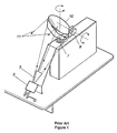
- the antenna has a fixed non-moving feed 3 and associated electronics 5 and, a gimbaled 7,9 main reflector 10. Only the reflector 10 is moved to scan the beam, depicted by the dotted lines and arrows marked 11. The shortfall of this antenna is that it incurs high scan losses which is compensates for by special design of the reflector 10 and feed 3, which is expensive.
- This antenna additionally utilizes a long focal length to minimize the scan loss which results in the antenna requiring a substantial amount of real estate on a spacecraft which is typically at a premium.
- the antenna also uses an oversized reflector 10 to compensate for the gain loss.
- What is needed therefore is a light weight antenna which has a low cross-polarization level and low beam distortion when scanned over a field of view, particularly when scanned over the Earth from a geosynchronous orbiting satellite.
- the steerable antenna assembly comprises a main reflector, a feed and a subreflector which together are oriented to define a side-fed dual reflector geometry where the feed is to a side of both the subreflector and the main reflector.
- the feed, subreflector and main reflector together producing an antenna beam which is directed in a preselected direction by the main reflector.
- a gimbal is coupled to the main reflector for positioning the main reflector and scanning the antenna beam over a preselected coverage area.
- the feed and subreflector remain substantially fixed in position when the main reflector is positioned and the antenna beam is scanned.
- the steerable antenna is coupled to a satellite in a geosynchronous orbit about the earth where the earth subtends approximately a twenty two degree cone of coverage from the satellite.
- the main reflector and gimbal are configured to scan the antenna beam over the earth field of view.
- FIG. 2 a portion 20 of a spacecraft having a reduced weight antenna system 22 for scanning an antenna beam is illustrated.
- the antenna system 22 of the present invention is preferably used for communications between the spacecraft and the Earth where the spacecraft is preferably located in a geosynchronous or near geosynchronous orbit and the antenna beam is scanned over an earth field of view.
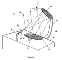
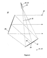
- FIGs. 2- 4 an embodiment of a scanning antenna assembly configured according to the invention is illustrated.
- FIGs. 2 & 3 depict the antenna assembly 22 in an isometric view fashion whereas FIG. 4 depicts the antenna assembly 22 in a side plane view fashion.
- the antenna assembly 22 includes a feed assembly 24, a subreflector 26 and a main reflector 28.
- the feed assembly 24 preferably contains a single feed horn and associated electronics but can also contain a feed array.
- the feed assembly 22, subreflector 26 and main reflector 28 are configured in a side-fed dual reflector antenna configuration. The location of the feed assembly 24 to the side of both the subreflector 26 and main reflector 28 define the antenna assembly 22 as being "side-fed.”
- the side-fed dual reflector configuration provides an optical system having a long effective focal length in a compact structure.
- a relatively long effective focal length of the optical system ensures low beam squint and virtually distortionless scanning to wide scan angles.
- Coupling a subreflector 26 with the main reflector 28 in a side-fed dual reflector configuration enables an optical system to be packaged into an extremely small envelope while providing an antenna 22 free of blockage.
- a more detailed discussion of side-fed dual reflector antenna configurations can be found in the article Jorgenson et al. "Development of dual reflector multibeam spacecraft antenna system," IEEE Transactions of Antennas and Propagation, vol. AP-32, pp. 30- 35, 1984. Note that the above description of the antenna pertains to the antenna being configured in a transmit mode. As is well known to one skilled in the art, the antenna can also be configured to operate in a receive mode.
- Table 1 below gives an example of the parameters of the antenna 22 in accordance with a first embodiment of the invention.
- the illumination beam depicted by the lines marked 30, are provided by the feed assembly 24 and are reflected by the subreflector 26 which directs the illumination beam 30 towards the main reflector 28.
- the illumination beam 30 is reflected from the main reflector 28 which produces an antenna beam.
- the antenna beam is directed in a preselected direction which is substantially or totally free of blockage by the subreflector 26 and feed assembly 24.
- a gimbal 34 is coupled to the main reflector 28 and angularly moves the main reflector 28.
- the gimbal 34 is a conventional electrical positioning and sensor device which steers the main reflector 28 over a preselected scan area; that is, positions the main reflector's attitude and elevation. Since the electronic controls and electrical leads and accompany electrical circuits for supplying driving current to the gimbal and sending position information therefrom are known and not necessary to an understanding of the invention, they are not illustrated or further described. As those skilled in the art recognize, many gimbal arrangements may be used to steer the reflector, such as a bi-axial gimbal attached to the back side of the main reflector 28.
- the feed assembly 24 and subreflector 26 are each positioned in preselected, fixed locations and do not move with the main reflector 28.
- the feed assembly 24 and subreflector 26 are preferably mounted to separate brackets 36, 38, respectively, which are each mounted to the bulkhead 40 of a spacecraft 20.
- the brackets 36, 38 serve to fix the location of the feed assembly 24 and subreflector 26 thereby maintaining substantially fixed the relative distance between the feed assembly 24 and subreflector 26.
- the main reflector 28 may be formed from a solid piece of metal that is concavely shaped into one of the conventional curves used for reflector type microwave antennas, such as parabolic or a section of a parabolic, or may be so formed of wire mesh or of composite graphite material, all of which are known structures.
- the subreflector 26 may also comprise a solid piece of metal or be formed of wire mesh or a composite material.
- the subreflector 26 preferably has the shape of a portion of a hyperbola having a concave side 42 with an associated focal point 44 and a convex side 46 with an associated focal point 48.
- the main reflector 28 has a main reflector focal point 50 and the subreflector 26 provides a secondary focus 52 for the main reflector 28.
- the feed assembly 24 becomes displaced from the secondary focus 52 of the main reflector 28 as the main reflector 28 is moved since the feed assembly 24 and subreflector 26 are held stationary during positioning of the main reflector 28.
- Displacing the feed assembly 24 from the secondary focus 52 of the main reflector 28 is normally associated with a large loss in gain, a high cross polarization level, a high sidelobe level and distortion in the beam shape. It was found that by using a side-fed antenna configuration, superior scanning performance can be realized even though the feed assembly 24 is displaced from the secondary focus 52 during scanning.
- the scan loss was only 0.6 dB
- the cross-polarization level increased by only 2.5 dB
- the sidelobe level increase only about 3 dB when the main reflector 28 was scanned +/- 11 degrees for a total scan of twenty two degrees.
- Good performance over an approximate twenty two degree scan angle is particularly desirable for an antenna used on a gyosynchronous satellite since the earth subtends approximately a twenty two degree cone angle from a geosynchronous orbit.
- the side-fed configuration has the additional advantage that the subreflector 26 does not block the main reflector 28.
- the subreflector 26 can be made to be oversized without incurring gain loss and distortion associated with subreflector blockage of the main reflector 28.
- Typical subreflectors 26 are sized to be approximately ten to twenty wavelengths in diameter at a frequency of operation.
- the feed assembly 24 is typically designed to illuminate the edge of the subreflector 26 at a -8 to -14 dB level. Energy which does not illuminate the subreflector 26 is lost. This lost energy is known in the art as "spillover loss". It has been determined that an oversized subreflector, preferably between 50 and 100 wavelengths in diameter at a frequency of operation, will significantly reduce spillover loss and thereby increase overall antenna gain.
- An additional benefit of the present invention is an improved long-term reliability of the antenna assembly 22.
- the gimbaled main reflector 28 eliminates any RF moving parts, such as RF rotary joint or flexible waveguide and cables, which are needed in some of the prior art gimbaled antenna approaches.
- the life, and consequently the performance degradation over life, of high frequency RF parts constantly flexing over a long period of time is always a design concern for a space-based system.
- the antenna assembly described above offers significant improvements over those antenna system known in the art for use on satellites.
- the antenna systems of the invention are able to generate high gain, low scan loss, nearly undistorted, symmetrically shaped antenna beams for many uses, such as satellite earth coverage from a geosynchronous satellite.
Landscapes
- Aerials With Secondary Devices (AREA)
- Variable-Direction Aerials And Aerial Arrays (AREA)
Abstract
Description
| Main Reflector | Subreflector |
| Vertex: x=0, y=0, z=0 | Focus: x=0, y=0, z=120" |
| Focal Length: 120" | Focus Distance: 70.9355" |
| RIM: | Rotation: 128.7101° |
| Center: x=90.2374", y=0, z=0 | RIM: |
| Diameter: 24" | Center x=18.31052", y=0, z=0 |
| Diameter: 20" |
Claims (10)
- A steerable antenna assembly comprising:a feed assembly positioned in a first fixed preselected location;a subreflector positioned in a second fixed preselected location and being stationary with respect to the feed assembly;a main reflector,the feed assembly, subreflector and main reflector oriented to define a side-fed dual reflector antenna geometry wherein the feed assembly is to a side of both the main reflector and the subreflector,the feed, subreflector and main reflector together providing an antenna beam, the main reflector directing the antenna beam in a preselected direction; and,a gimbal coupled to the main reflector for positioning the main reflector and scanning the antenna beam over a preselected coverage area.
- An antenna assembly as in claim 1, wherein the preselected coverage area has a center point of coverage, the main reflector has a focal point, the subreflector being in the shape of a hyperbola and having a concave side and a convex side, the hyperbola having first and a second focus associated with the concave and convex sides, respectively, the subreflector positioned so that the first focal point and the main reflector focal points are coincident, the feed assembly being positioned at the second focus when the antenna beam is directed at the center point of coverage, whereby scanning the main reflector over the preselected coverage area displaces the main reflector focal point from the second focus.
- The antenna assembly as in claims 1 or 2, wherein the preselected coverage area is an earth field of view from a satellite in geosynchronous orbit.
- The antenna assembly system as in one of claims 1 to 3, wherein the configuration of the feed assembly, subreflector and main reflector satisfy a cross-polarization cancellation condition give by tan γ / 2 = 1 / M x tan ϕ / 2.
- An antenna assembly as in one of claims 1 to 4, wherein the antenna assembly has a scan loss which does not exceed 0.6 dB when the main reflector is scanned over an approximate 22 degree scan cone.
- A satellite in a geosynchronous orbit about earth having a bulkhead with a steerable antenna mounted thereto, the antenna comprising:a feed assembly mounted to the bulkhead in a first fixed preselected location;a subreflector mounted to the bulkhead in a second fixed preselected location which is stationary with respect to the location of the feed assembly;a main reflector,the feed assembly, subreflector and main reflector configured to define a side-fed dual reflector antenna geometry wherein the feed assembly is to a side of both the main reflector and the subreflector, the feed assembly, subreflector and main reflector together generating an antenna beam which is directed towards earth by the main reflector; and,a positioning mechanism coupled to the main reflector and operative to position the main reflector in attitude and elevation, the main reflector and gimbal being configured to scan the antenna beam over the earth free of moving the feed assembly and the subreflector.
- An antenna as in claim 6, wherein the subreflector is greater than approximately 50 wavelengths at a frequency of operation.
- An antenna as in claim 6 or 7, wherein the main reflector and positioning mechanism are configured to scan the antenna beam over an approximate 22 degree scan cone.
- An antenna as in claim 8, wherein the main reflector has a focal point, the subreflector being in the shape of a hyperbola having a concave side and a convex side, the subreflector having a first focal point associated with the concave side and a second focus associated with the convex side, the subreflector positioned so that the first focal point and the main reflector focal points are coincident, the feed assembly being positioned substantially at the second focus when the antenna beam is directed at a center of the earth coverage area, whereby scanning the antenna beam over the coverage area displaces the main reflector focal point from the secondary focus.
- The antenna system as in one of claims 6 to 9, wherein the configuration of the feed assembly, subreflector and main reflector satisfy a cross-polarization cancellation condition give by tan γ / 2 = 1 / M x tan ϕ / 2.
Applications Claiming Priority (2)
| Application Number | Priority Date | Filing Date | Title |
|---|---|---|---|
| US725616 | 2000-11-29 | ||
| US09/725,616 US6342865B1 (en) | 2000-11-29 | 2000-11-29 | Side-fed offset cassegrain antenna with main reflector gimbal |
Publications (2)
| Publication Number | Publication Date |
|---|---|
| EP1213788A2 true EP1213788A2 (en) | 2002-06-12 |
| EP1213788A3 EP1213788A3 (en) | 2003-07-16 |
Family
ID=24915291
Family Applications (1)
| Application Number | Title | Priority Date | Filing Date |
|---|---|---|---|
| EP01125453A Withdrawn EP1213788A3 (en) | 2000-11-29 | 2001-11-05 | Side-fed offset cassegrain antenna with main reflector gimbal |
Country Status (4)
| Country | Link |
|---|---|
| US (1) | US6342865B1 (en) |
| EP (1) | EP1213788A3 (en) |
| JP (1) | JP2002204124A (en) |
| CA (1) | CA2359631A1 (en) |
Cited By (1)
| Publication number | Priority date | Publication date | Assignee | Title |
|---|---|---|---|---|
| EP4693728A1 (en) | 2024-08-06 | 2026-02-11 | Sener Aeroespacial, S.A. | Steerable antenna for spacecraft, and process of deploying the steerable antenna |
Families Citing this family (12)
| Publication number | Priority date | Publication date | Assignee | Title |
|---|---|---|---|---|
| WO2003026173A1 (en) * | 2001-09-14 | 2003-03-27 | Andrew Corporation | Co-located antenna design |
| US6634601B2 (en) * | 2002-01-11 | 2003-10-21 | Northrop Grumman Corporation | Attitude sensor for spacecraft |
| US6774861B2 (en) * | 2002-06-19 | 2004-08-10 | Northrop Grumman Corporation | Dual band hybrid offset reflector antenna system |
| JP2006261994A (en) * | 2005-03-16 | 2006-09-28 | Toshiba Corp | Antenna device |
| US7205949B2 (en) * | 2005-05-31 | 2007-04-17 | Harris Corporation | Dual reflector antenna and associated methods |
| US7786945B2 (en) * | 2007-02-26 | 2010-08-31 | The Boeing Company | Beam waveguide including Mizuguchi condition reflector sets |
| US7705796B2 (en) * | 2007-06-27 | 2010-04-27 | The Boeing Company | Dual offset reflector system utilizing at least one gimbal mechanism |
| US7855691B2 (en) * | 2008-08-07 | 2010-12-21 | Toyota Motor Engineering & Manufacturing North America, Inc. | Automotive radar using a metamaterial lens |
| US20120274507A1 (en) * | 2011-04-28 | 2012-11-01 | Jaafar Cherkaoui | Architecture and method for optimal tracking of multiple broadband satellite terminals in support of in theatre and rapid deployment applications |
| US9335015B2 (en) | 2012-01-23 | 2016-05-10 | 3M Innovative Properties Company | Off-axis cassegrain solar collector |
| US9871292B2 (en) * | 2015-08-05 | 2018-01-16 | Harris Corporation | Steerable satellite antenna assembly with fixed antenna feed and associated methods |
| US11973272B2 (en) | 2019-04-18 | 2024-04-30 | Institute For Q-Shu Pioneers Of Space, Inc. | Antenna apparatus and spacecraft |
Family Cites Families (9)
| Publication number | Priority date | Publication date | Assignee | Title |
|---|---|---|---|---|
| FR2517626A1 (en) * | 1981-12-04 | 1983-06-10 | Europ Agence Spatiale | ORBITAL SPACE ENGINE, IN PARTICULAR SATELLITE, WITH MULTIPLE MISSIONS |
| US4439773A (en) * | 1982-01-11 | 1984-03-27 | Bell Telephone Laboratories, Incorporated | Compact scanning beam antenna feed arrangement |
| JPS5991708A (en) * | 1982-11-17 | 1984-05-26 | Mitsubishi Electric Corp | Antenna device |
| US4866457A (en) * | 1988-11-08 | 1989-09-12 | The United States Of America As Represented By The Secretary Of Commerce | Covered inverted offset cassegrainian system |
| FR2713404B1 (en) * | 1993-12-02 | 1996-01-05 | Alcatel Espace | Oriental antenna with conservation of polarization axes. |
| US5579018A (en) * | 1995-05-11 | 1996-11-26 | Space Systems/Loral, Inc. | Redundant differential linear actuator |
| US5859619A (en) * | 1996-10-22 | 1999-01-12 | Trw Inc. | Small volume dual offset reflector antenna |
| US5714947A (en) * | 1997-01-28 | 1998-02-03 | Northrop Grumman Corporation | Vehicle collision avoidance system |
| US6043788A (en) * | 1998-07-31 | 2000-03-28 | Seavey; John M. | Low earth orbit earth station antenna |
-
2000
- 2000-11-29 US US09/725,616 patent/US6342865B1/en not_active Expired - Lifetime
-
2001
- 2001-10-23 CA CA002359631A patent/CA2359631A1/en not_active Abandoned
- 2001-11-05 EP EP01125453A patent/EP1213788A3/en not_active Withdrawn
- 2001-11-26 JP JP2001359104A patent/JP2002204124A/en not_active Withdrawn
Cited By (1)
| Publication number | Priority date | Publication date | Assignee | Title |
|---|---|---|---|---|
| EP4693728A1 (en) | 2024-08-06 | 2026-02-11 | Sener Aeroespacial, S.A. | Steerable antenna for spacecraft, and process of deploying the steerable antenna |
Also Published As
| Publication number | Publication date |
|---|---|
| JP2002204124A (en) | 2002-07-19 |
| EP1213788A3 (en) | 2003-07-16 |
| CA2359631A1 (en) | 2002-05-29 |
| US6342865B1 (en) | 2002-01-29 |
Similar Documents
| Publication | Publication Date | Title |
|---|---|---|
| US5859619A (en) | Small volume dual offset reflector antenna | |
| US9281561B2 (en) | Multi-band antenna system for satellite communications | |
| US4618867A (en) | Scanning beam antenna with linear array feed | |
| US6236375B1 (en) | Compact offset gregorian antenna system for providing adjacent, high gain, antenna beams | |
| US6043788A (en) | Low earth orbit earth station antenna | |
| US5130718A (en) | Multiple dichroic surface cassegrain reflector | |
| US6342865B1 (en) | Side-fed offset cassegrain antenna with main reflector gimbal | |
| CA1067204A (en) | Satellite tracking antenna with multiple reflectors | |
| WO1999060656A8 (en) | Multibeam satellite communication antenna | |
| US11831346B2 (en) | Adaptable, reconfigurable mobile very small aperture (VSAT) satellite communication terminal using an electronically scanned array (ESA) | |
| EP0597318B1 (en) | Multibeam antenna for receiving satellite | |
| EP1119072B1 (en) | Antenna cluster configuration for wide-angle coverage | |
| US6061033A (en) | Magnified beam waveguide antenna system for low gain feeds | |
| CA2293931C (en) | A compact side-fed dual reflector antenna system for providing adjacent, high gain antenna beams | |
| US6747604B2 (en) | Steerable offset antenna with fixed feed source | |
| US9871292B2 (en) | Steerable satellite antenna assembly with fixed antenna feed and associated methods | |
| US6580399B1 (en) | Antenna system having positioning mechanism for reflector | |
| US6577282B1 (en) | Method and apparatus for zooming and reconfiguring circular beams for satellite communications | |
| EP1014483B1 (en) | A rotatable and scannable reflector with a moveable feed system | |
| EP0921590A2 (en) | Antenna for communicating with low earth orbit satellite | |
| US6225964B1 (en) | Dual gridded reflector antenna system | |
| Vilenko et al. | Millimeter wave reflector antenna with wide angle mechanical beam scanning | |
| US6243047B1 (en) | Single mirror dual axis beam waveguide antenna system | |
| US4814778A (en) | Large scan antenna with fixed main reflector and fixed feed, particularly for use at ultrahigh frequencies, carried on board a satellite and a satellite equipped with such an antenna | |
| US6172649B1 (en) | Antenna with high scanning capacity |
Legal Events
| Date | Code | Title | Description |
|---|---|---|---|
| PUAI | Public reference made under article 153(3) epc to a published international application that has entered the european phase |
Free format text: ORIGINAL CODE: 0009012 |
|
| AK | Designated contracting states |
Kind code of ref document: A2 Designated state(s): AT BE CH CY DE DK ES FI FR GB GR IE IT LI LU MC NL PT SE TR |
|
| AX | Request for extension of the european patent |
Free format text: AL;LT;LV;MK;RO;SI |
|
| PUAL | Search report despatched |
Free format text: ORIGINAL CODE: 0009013 |
|
| AK | Designated contracting states |
Designated state(s): AT BE CH CY DE DK ES FI FR GB GR IE IT LI LU MC NL PT SE TR |
|
| AX | Request for extension of the european patent |
Extension state: AL LT LV MK RO SI |
|
| RAP1 | Party data changed (applicant data changed or rights of an application transferred) |
Owner name: NORTHROP GRUMMAN CORPORATION |
|
| RAP1 | Party data changed (applicant data changed or rights of an application transferred) |
Owner name: NORTHROP GRUMMAN CORPORATION |
|
| AKX | Designation fees paid | ||
| REG | Reference to a national code |
Ref country code: DE Ref legal event code: 8566 |
|
| STAA | Information on the status of an ep patent application or granted ep patent |
Free format text: STATUS: THE APPLICATION IS DEEMED TO BE WITHDRAWN |
|
| 18D | Application deemed to be withdrawn |
Effective date: 20040117 |