EP1213717A2 - Magneto-optical recording medium - Google Patents
Magneto-optical recording medium Download PDFInfo
- Publication number
- EP1213717A2 EP1213717A2 EP01127437A EP01127437A EP1213717A2 EP 1213717 A2 EP1213717 A2 EP 1213717A2 EP 01127437 A EP01127437 A EP 01127437A EP 01127437 A EP01127437 A EP 01127437A EP 1213717 A2 EP1213717 A2 EP 1213717A2
- Authority
- EP
- European Patent Office
- Prior art keywords
- magneto
- layer
- magnetic
- magnetic layer
- recording medium
- Prior art date
- Legal status (The legal status is an assumption and is not a legal conclusion. Google has not performed a legal analysis and makes no representation as to the accuracy of the status listed.)
- Withdrawn
Links
Images





Classifications
-
- G—PHYSICS
- G11—INFORMATION STORAGE
- G11B—INFORMATION STORAGE BASED ON RELATIVE MOVEMENT BETWEEN RECORD CARRIER AND TRANSDUCER
- G11B11/00—Recording on or reproducing from the same record carrier wherein for these two operations the methods are covered by different main groups of groups G11B3/00 - G11B7/00 or by different subgroups of group G11B9/00; Record carriers therefor
- G11B11/10—Recording on or reproducing from the same record carrier wherein for these two operations the methods are covered by different main groups of groups G11B3/00 - G11B7/00 or by different subgroups of group G11B9/00; Record carriers therefor using recording by magnetic means or other means for magnetisation or demagnetisation of a record carrier, e.g. light induced spin magnetisation; Demagnetisation by thermal or stress means in the presence or not of an orienting magnetic field
- G11B11/105—Recording on or reproducing from the same record carrier wherein for these two operations the methods are covered by different main groups of groups G11B3/00 - G11B7/00 or by different subgroups of group G11B9/00; Record carriers therefor using recording by magnetic means or other means for magnetisation or demagnetisation of a record carrier, e.g. light induced spin magnetisation; Demagnetisation by thermal or stress means in the presence or not of an orienting magnetic field using a beam of light or a magnetic field for recording by change of magnetisation and a beam of light for reproducing, i.e. magneto-optical, e.g. light-induced thermomagnetic recording, spin magnetisation recording, Kerr or Faraday effect reproducing
- G11B11/10582—Record carriers characterised by the selection of the material or by the structure or form
- G11B11/10586—Record carriers characterised by the selection of the material or by the structure or form characterised by the selection of the material
-
- G—PHYSICS
- G11—INFORMATION STORAGE
- G11B—INFORMATION STORAGE BASED ON RELATIVE MOVEMENT BETWEEN RECORD CARRIER AND TRANSDUCER
- G11B11/00—Recording on or reproducing from the same record carrier wherein for these two operations the methods are covered by different main groups of groups G11B3/00 - G11B7/00 or by different subgroups of group G11B9/00; Record carriers therefor
- G11B11/10—Recording on or reproducing from the same record carrier wherein for these two operations the methods are covered by different main groups of groups G11B3/00 - G11B7/00 or by different subgroups of group G11B9/00; Record carriers therefor using recording by magnetic means or other means for magnetisation or demagnetisation of a record carrier, e.g. light induced spin magnetisation; Demagnetisation by thermal or stress means in the presence or not of an orienting magnetic field
- G11B11/105—Recording on or reproducing from the same record carrier wherein for these two operations the methods are covered by different main groups of groups G11B3/00 - G11B7/00 or by different subgroups of group G11B9/00; Record carriers therefor using recording by magnetic means or other means for magnetisation or demagnetisation of a record carrier, e.g. light induced spin magnetisation; Demagnetisation by thermal or stress means in the presence or not of an orienting magnetic field using a beam of light or a magnetic field for recording by change of magnetisation and a beam of light for reproducing, i.e. magneto-optical, e.g. light-induced thermomagnetic recording, spin magnetisation recording, Kerr or Faraday effect reproducing
- G11B11/10582—Record carriers characterised by the selection of the material or by the structure or form
- G11B11/10584—Record carriers characterised by the selection of the material or by the structure or form characterised by the form, e.g. comprising mechanical protection elements
-
- Y—GENERAL TAGGING OF NEW TECHNOLOGICAL DEVELOPMENTS; GENERAL TAGGING OF CROSS-SECTIONAL TECHNOLOGIES SPANNING OVER SEVERAL SECTIONS OF THE IPC; TECHNICAL SUBJECTS COVERED BY FORMER USPC CROSS-REFERENCE ART COLLECTIONS [XRACs] AND DIGESTS
- Y10—TECHNICAL SUBJECTS COVERED BY FORMER USPC
- Y10T—TECHNICAL SUBJECTS COVERED BY FORMER US CLASSIFICATION
- Y10T428/00—Stock material or miscellaneous articles
- Y10T428/11—Magnetic recording head
- Y10T428/1107—Magnetoresistive
- Y10T428/1121—Multilayer
Definitions
- the present invention relates to a magneto-optical recording medium such as a magneto-optical disc, a magneto-optical card, or magneto-optical tape, which is used for a magneto-optical recording and reproducing apparatus.
- MSR magnetically induced super resolution
- the resolution is increased by using the following techniques: providing at least a magnetic recording layer (hereinafter referred to as a recording layer) and a magnetic reproducing layer (hereinafter referred to as a reproducing layer) on a magneto-optical recording medium; generating a temperature distribution in the medium by laser beam irradiation for reproduction, wherein the laser beam is focused on the medium to form a beam spot; transferring, by using the temperature distribution, the magnetization of the recording layer only to a region of the reproducing layer having a specific temperature, wherein the region having the specific temperature is called an aperture; and forming a magnetic mask in another region having a temperature other than the specific temperature.
- the MSR technologies are excellent in increasing resolution without changing a main parameter, such as optical pickup characteristics, of the magneto-optical recording and reproducing apparatus.
- CAD Center Aperture Detection
- the magneto-optical recording medium 10 has the following layers: a reproducing layer 11 of which the magnetic anisotropy changes from a in-plane direction to a perpendicular direction at a predetermined temperature Tc 1 ; an auxiliary reproducing layer 12 which has a Curie temperature Tc 2 higher than the predetermined temperature Tc 1 and has a in-plane magnetic anisotropy up to the Curie temperature Tc 2 ; a non-magnetic layer 14 composed of an Al alloy, a dielectric material such as SiN or AlN, or the like; and a recording layer 13 having a perpendicular magnetic anisotropy up to the Curie temperature.
- the temperature distribution generated on the magneto-optical recording medium 10 has a peak at the center of a curve 15 in FIG. 9.
- the reproducing layer 11 has in-plane magnetic anisotropy in a low temperature range, the magnetic domains of the recording layer 13 are not transferred to a region of the reproducing layer 11 having a low temperature, that is, the region functions as a mask.
- the exchange coupling force of the auxiliary reproducing layer 12 maintains a strong in-plane magnetic anisotropy to increase mask performance.
- the MSR technology based on CAD increases the resolutions of both the linear density and the recording track width.
- the technology reduces distortion generated in waveforms of the reproduced carriers because the aperture is located in the vicinity of the center of the laser beam spot.
- CAD is an excellent technology but has the following problems: sensitiveness to disturbances; instability in size of an aperture; and large noise.
- the problems are caused by using only the aperture having the highest temperature in the temperature distribution generated by laser beam irradiation because the magnetic coupling force is used for transferring the magnetic recording information, namely, magnetic domains, in the recording layer 13.
- the strength of the leaked magnetic field varies according to the size of the magnetic domain of the recording layer 13, that is, a leaked magnetic field generated from a long recorded magnetic domain is stronger than another leaked magnetic field generated from a short recorded magnetic domain.
- the strength of the leaked magnetic field significantly affects carrier reproduction characteristics of the magnetic domains according to the recorded state thereof.
- the long recorded magnetic domain is not perfectly transferred to a reproducing layer. Consequently, the following phenomenon frequently arises: the ratio of the bit error rate to the magnetic recording field is large even if the ratio of the carrier-noise intensity rate to the magnetic recording field or the rate of jitter to the magnetic recording field is small.
- the magneto-optical recording medium for recording and reproducing carriers by laser beam irradiation includes a first magnetic layer which is magnetized in the in-plane direction at room temperature and is perpendicularly magnetized at a predetermined temperature T 1 or more; a second magnetic layer which is in contact with the first magnetic layer, has a Curie temperature Tc 2 higher than the predetermined temperature T 1 , and has in-plane magnetic anisotropy up to the Curie temperature Tc 2 ; a third magnetic layer which has a Curie temperature Tc 3 higher than the predetermined temperature T 1 and has perpendicular magnetic anisotropy at least in a predetermined range of a temperature distribution of the magneto-optical recording medium during laser beam irradiation when reproducing; and a rare earth metal layer formed between the third magnetic layer and the second magnetic layer.
- the magneto-optical recording medium preferably includes a transparent substrate on which the first magnetic layer, the second magnetic layer, the rare earth metal layer, and the third magnetic layer are deposited in that order.
- the rare earth metal layer of the magneto-optical recording medium is preferably composed of Gd.
- the rare earth metal layer preferably has a thickness of 1 to 20 nm.
- the magneto-optical recording medium preferably includes a fourth magnetic layer in contact with a face of the third magnetic layer away from the rare earth metal layer, wherein the fourth magnetic layer comprises a rare earth-transition metal alloy.
- the magneto-optical recording medium of the present invention reproduces carriers with a reduced power, that is, a wide range of power is usable for the magneto-optical disc when reproducing carriers, and thus that is advantageous for designing the driving device for the magneto-optical recording medium such as a magneto-optical disc.
- the magneto-optical recording medium a small power is usable for reproducing; hence, the aperture used for reproducing carriers is reduced, and miniaturization of the track pitch and high recording density in the linear direction are achieved.
- the operation for transferring the magnetic recording domains of the recording layer to the reproducing layer is stable; hence, the ratio of carrier intensity to noise intensity increases.
- the magneto-optical recording medium has the following advantages in practical use: improvement of the relationship between jitter and error; reduction of the current used for a magnetic head of the recording and reproducing apparatus; and reduction of electricity consumed by a driving device for the magneto-optical disc.
- FIG. 1 is a schematic sectional view showing an exemplary magneto-optical recording medium of the present invention.
- the magneto-optical recording medium 20 for recording and reproducing carriers by laser beam irradiation has a first magnetic layer which is magnetized in the in-plane direction at room temperature and is perpendicularly magnetized at a predetermined temperature T 1 or more; a second magnetic layer which is in contact with the first magnetic layer and has a Curie temperature Tc 2 higher than the predetermined temperature T 1 and in-plane magnetic anisotropy up to the Curie temperature Tc 2 ; a third magnetic layer which has a Curie temperature Tc 3 higher than the predetermined temperature T 1 , wherein T 1 ⁇ Tc 2 ⁇ Tc 3 , and has perpendicular magnetic anisotropy at least in a predetermined range of a temperature distribution of the magneto-optical recording medium during laser beam irradiation when reproducing carriers; and a rare earth metal layer formed between the third magnetic layer and the second magnetic layer.
- a transparent substrate 21 composed of polycarbonate in the following order by magnetron sputtering: a first dielectric layer 31, a first magnetic layer 1 functioning as a reproducing layer, a second magnetic layer 2 functioning as an auxiliary reproducing layer, a rare earth metal layer 5, a third magnetic layer 3 functioning as a recording layer, a fourth magnetic layer 4 functioning as an auxiliary recording layer, a second dielectric layer 32, and a heat radiation layer 22.
- a protective layer 23 was formed on the top of these layers by spin coating.
- the first magnetic layer 31 and the second magnetic layer 32 were composed of AlN, and the heat radiation layer 22 was composed of an Al alloy.
- the reproducing layer namely, the first magnetic layer 1, was composed of GdFeCo which has in-plane magnetic anisotropy at room temperature but has perpendicular magnetic anisotropy at high temperature.
- the auxiliary reproducing layer namely, the second magnetic layer 2
- the rare earth metal layer 5 was composed of Gd and had a thickness of 3 nm.
- the recording layer namely, the third magnetic layer 3, was composed of TbFeCo which is generally used for magneto-optical recording media.
- the auxiliary reproducing layer namely, the first magnetic layer 4 composed of GdFeCo functions so as to enhance the magnetic recording field sensitivity, has a smaller coercive force than that of the recording layer 3, and has a higher Curie temperature than that of the recording layer.
- the Ar gas pressure used for depositing the recording layer 3 was adjusted to be lower than that used for depositing the reproducing layer in order to enhance the magnetic recording field sensitivity and to stabilize the operation for transferring the magnetic domain of the recording layer 3 to the reproducing layer 1.
- FIG. 2 is a schematic sectional view showing COMPARATIVE EXAMPLE 1 of the magneto-optical recording medium.
- the structure disclosed in Japanese Unexamined Patent Application Publication No. 9-320134 described above was modified as follows: an auxiliary reproducing layer 4 was added; and a non-magnetic layer 6 composed of an Al alloy having a thickness of 3 nm was provided instead of the rare earth metal layer 5 of the present invention.
- the magneto-optical recording medium of the comparative example had the same structure as that of the EXAMPLE except for the non-magnetic layer 6.
- the dependence of signal intensities of carriers and noise reproduced from repeated marks having a length of 0.24 ⁇ m and 0.97 ⁇ m on the reproducing power was measured.
- the light spot used in this measurement was obtained by focusing a laser beam having a wavelength of 403 nm with an objective lens having a numerical aperture of 0.6.
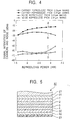
- FIGS. 3 and 4 show the measurement results of the dependence on the magneto-optical discs 20 and 40.
- the abscissa represents the reproducing power
- the ordinate represents intensities of the reproduced carriers and the reproduced noise.
- Curves A and B show the intensities of the carriers reproduced from the 0.24- ⁇ m and 0.97- ⁇ m repeated marks, respectively.
- Curves C and D show the intensities of the noise reproduced from the 0.24- ⁇ m and 0.97- ⁇ m repeated marks, respectively.
- the optimum reproducing power is 2.6 mW when the magneto-optical discs 20 and 40 with recorded random lengths of carriers have the best reproducing performance.
- the magneto-optical disc 40 When the magneto-optical disc 40 is reproduced with a reproducing power of about 1.8 mW, that is, a small reproducing power, noise obtained from the 0.97 ⁇ m marks is large.
- the magneto-optical disc 20 is reproduced with a reproducing power of about 1.8 mW, that is, a small reproducing power, noise obtained from the 0.97 ⁇ m marks is small.
- the magneto-optical disc of the present invention can reproduce carriers with a reduced power, that is, a wide range of power is usable for the magneto-optical disc when reproducing carriers, which is advantageous in designing the driving device for the magneto-optical disc.
- Retrieval with a reduced power means that the aperture used for reproducing carriers is small; hence, the track pitch is narrow and the recording density is increased.
- the same track pitch as that of the magneto-optical disc disclosed in Japanese Unexamined Patent Application Publication No. 9-320134 described above is used, a wide range of power is usable for reproducing, which is advantageous in designing the driving device for the magneto-optical disc.
- FIG. 5 is a sectional view showing the main part of a magneto-optical disc, namely, a magneto-optical recording medium 50 which does not have the rare earth metal layer 5 provided in the magneto-optical disc 20 described above.
- FIG. 6 shows that small reproducing power does not cause the noise to increase, and thus a wide range of power is usable for reproduction.
- the ratio of the intensity of the carrier reproduced from the long mark to that of the other carrier reproduced from the short mark is larger than that of the magneto-optical disc 20 of the present invention.
- the mask efficiency during reproduction of carriers namely, the reproduction resolution is inferior, and the performance desired for a magneto-optical recording medium having high magnetic resolution is inferior.
- the magneto-optical recording medium of the present invention has a high resolution and is reproduced with a wide range of power.
- the signal characteristics of the magneto-optical discs 20 and 40 were measured.
- a laser beam having a wavelength of 403 nm was focused with an objective lens having a numerical aperture of 0.6, the beam was focused to a spot, and the reproducing power was 2.6 mW.
- Random signals of RLL (1, 7) modulation were recorded and the density in the linear direction was 0.182 ⁇ m/bit.
- partial response equalization and Viterbi decoding were used.
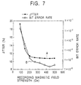
- FIG. 7 shows relationships between the magnetic recording field and the jitter (Curve A) and between the magnetic recording field and the bit error rate (Curve B) in the magneto-optical disc 20.
- FIG. 8 shows relationships between the magnetic recording field and the jitter (Curve A) and between the magnetic recording field and a bit error rate (Curve B) in the magneto-optical disc 40.
- the jitter is the standard deviation of the time difference between a clock edge formed from a reproduced carrier and a data edge of a binarized reproduced carrier.
- the jitter of the magneto-optical discs 20 and 40 are substantially same; however, the bit error rate of the magneto-optical disc 20 of the present invention is one order of magnitude smaller than that of the magneto-optical disc 40 ranging over the entire gamut of the magnetic recording field.
- the results show that the magneto-optical disc 20 of the present invention reliably performs the transferring operation compared with the magneto-optical disc 40; hence, the magneto-optical disc 20 exhibits excellent performance as a digital signal-recording medium.
- the Gd layer namely, the rare earth metal layer 5 having a thickness of 3 nm was placed between the recording layer 3 and the auxiliary reproducing layer 2.
- Magneto-optical recording media were prepared by changing the thickness in the range of 1 to 20 nm and the resulting media exhibited the same performance as that in the EXAMPLE.
- the reproducing power is small and the noise is reduced.
Abstract
A magneto-optical recording medium for recording and reproducing carriers by laser beam irradiation includes a first magnetic layer (reproducing layer 1) which is magnetized in the in-plane direction at room temperature and is perpendicularly magnetized at a predetermined temperature T1 or more; a second magnetic layer (auxiliary reproducing layer 2) which is in contact with the first magnetic layer, has a Curie temperature Tc2 higher than the predetermined temperature T1, and has in-plane magnetic anisotropy up to the Curie temperature Tc2; a third magnetic layer (recording layer 3) which has a Curie temperature Tc3 higher than the predetermined temperature T1 and has perpendicular magnetic anisotropy at least in a predetermined range of a temperature distribution of the magneto-optical recording medium during laser beam irradiation when reproducing; and a rare earth metal layer (5) formed between the third magnetic layer and the second magnetic layer. <IMAGE>
Description
The present invention relates to a magneto-optical
recording medium such as a magneto-optical disc, a magneto-optical
card, or magneto-optical tape, which is used for a
magneto-optical recording and reproducing apparatus.
For magneto-optical recording media, many new
technologies called magnetically induced super resolution
(MSR), which overcome optical limitations caused by the
numerical aperture NA of an objective lens and the laser
beam wavelength λ, have been proposed.
In these technologies, the resolution is increased by
using the following techniques: providing at least a
magnetic recording layer (hereinafter referred to as a
recording layer) and a magnetic reproducing layer
(hereinafter referred to as a reproducing layer) on a
magneto-optical recording medium; generating a temperature
distribution in the medium by laser beam irradiation for
reproduction, wherein the laser beam is focused on the
medium to form a beam spot; transferring, by using the
temperature distribution, the magnetization of the recording
layer only to a region of the reproducing layer having a
specific temperature, wherein the region having the specific
temperature is called an aperture; and forming a magnetic
mask in another region having a temperature other than the
specific temperature. The MSR technologies are excellent in
increasing resolution without changing a main parameter,
such as optical pickup characteristics, of the magneto-optical
recording and reproducing apparatus.
In the MSR technologies, an example of this technology
called Center Aperture Detection (CAD), which decreases both
the linear density and the recording track width and reduces
distortion generated in waveforms of reproduced signals
(hereinafter referred to as carriers), is disclosed in the
Japanese Unexamined Patent Application Publication No. 9-320134.
Referring to FIG. 9, the reproduction principle of the
magneto-optical recording medium disclosed the Japanese
Unexamined Patent Application Publication No. 9-320124 will
be now described.
The magneto-optical recording medium 10 has the
following layers: a reproducing layer 11 of which the
magnetic anisotropy changes from a in-plane direction to a
perpendicular direction at a predetermined temperature Tc1;
an auxiliary reproducing layer 12 which has a Curie
temperature Tc2 higher than the predetermined temperature Tc1
and has a in-plane magnetic anisotropy up to the Curie
temperature Tc2; a non-magnetic layer 14 composed of an Al
alloy, a dielectric material such as SiN or AlN, or the
like; and a recording layer 13 having a perpendicular
magnetic anisotropy up to the Curie temperature.
In the recording layer 13, magnetic domains having
different directions of magnetization are formed according
to information. By being irradiated with a reproducing
laser beam LB focused with an objective lens or the like
into a spot, the temperature distribution generated on the
magneto-optical recording medium 10 has a peak at the center
of a curve 15 in FIG. 9.
As described above, because the reproducing layer 11
has in-plane magnetic anisotropy in a low temperature range,
the magnetic domains of the recording layer 13 are not
transferred to a region of the reproducing layer 11 having a
low temperature, that is, the region functions as a mask.
In the above temperature range, the exchange coupling
force of the auxiliary reproducing layer 12 maintains a
strong in-plane magnetic anisotropy to increase mask
performance.
On the other hand, a part of the reproducing layer 11
which is in a region of the auxiliary reproducing layer 12
having a higher temperature than the Curie temperature Tc2
is released from the magnetic constraint force of the
auxiliary reproducing layer 12 to be formed into the
aperture. The magnetic domains of the recording layer 13
are transferred to the resulting aperture by the
magnetostatic coupling force of the magnetic field leaking
from the recording layer 13.
According to the above reproduction principle, the MSR
technology based on CAD increases the resolutions of both
the linear density and the recording track width. The
technology reduces distortion generated in waveforms of the
reproduced carriers because the aperture is located in the
vicinity of the center of the laser beam spot.
As described above, CAD is an excellent technology but
has the following problems: sensitiveness to disturbances;
instability in size of an aperture; and large noise. The
problems are caused by using only the aperture having the
highest temperature in the temperature distribution
generated by laser beam irradiation because the magnetic
coupling force is used for transferring the magnetic
recording information, namely, magnetic domains, in the
recording layer 13.
The strength of the leaked magnetic field varies
according to the size of the magnetic domain of the
recording layer 13, that is, a leaked magnetic field
generated from a long recorded magnetic domain is stronger
than another leaked magnetic field generated from a short
recorded magnetic domain.
The strength of the leaked magnetic field significantly
affects carrier reproduction characteristics of the magnetic
domains according to the recorded state thereof. Thus, in
particular, when magnetic domains are defective in recording,
the long recorded magnetic domain is not perfectly
transferred to a reproducing layer. Consequently, the
following phenomenon frequently arises: the ratio of the
bit error rate to the magnetic recording field is large even
if the ratio of the carrier-noise intensity rate to the
magnetic recording field or the rate of jitter to the
magnetic recording field is small.
Accordingly, it is an object of the present invention
to provide a magneto-optical recording medium which solves
the problems described above.
The magneto-optical recording medium for recording and
reproducing carriers by laser beam irradiation, according to
the present invention, includes a first magnetic layer which
is magnetized in the in-plane direction at room temperature
and is perpendicularly magnetized at a predetermined
temperature T1 or more; a second magnetic layer which is in
contact with the first magnetic layer, has a Curie
temperature Tc2 higher than the predetermined temperature T1,
and has in-plane magnetic anisotropy up to the Curie
temperature Tc2; a third magnetic layer which has a Curie
temperature Tc3 higher than the predetermined temperature T1
and has perpendicular magnetic anisotropy at least in a
predetermined range of a temperature distribution of the
magneto-optical recording medium during laser beam
irradiation when reproducing; and a rare earth metal layer
formed between the third magnetic layer and the second
magnetic layer.
The magneto-optical recording medium preferably
includes a transparent substrate on which the first magnetic
layer, the second magnetic layer, the rare earth metal layer,
and the third magnetic layer are deposited in that order.
The rare earth metal layer of the magneto-optical
recording medium is preferably composed of Gd.
The rare earth metal layer preferably has a thickness
of 1 to 20 nm.
The magneto-optical recording medium preferably
includes a fourth magnetic layer in contact with a face of
the third magnetic layer away from the rare earth metal
layer, wherein the fourth magnetic layer comprises a rare
earth-transition metal alloy.
The magneto-optical recording medium of the present
invention reproduces carriers with a reduced power, that is,
a wide range of power is usable for the magneto-optical disc
when reproducing carriers, and thus that is advantageous for
designing the driving device for the magneto-optical
recording medium such as a magneto-optical disc.
In the magneto-optical recording medium, a small power
is usable for reproducing; hence, the aperture used for
reproducing carriers is reduced, and miniaturization of the
track pitch and high recording density in the linear
direction are achieved.
Also, when reproducing carriers, the operation for
transferring the magnetic recording domains of the recording
layer to the reproducing layer is stable; hence, the ratio
of carrier intensity to noise intensity increases.
Furthermore, the magneto-optical recording medium has
the following advantages in practical use: improvement of
the relationship between jitter and error; reduction of the
current used for a magnetic head of the recording and
reproducing apparatus; and reduction of electricity consumed
by a driving device for the magneto-optical disc.
FIG. 1 is a schematic sectional view showing an
exemplary magneto-optical recording medium of the present
invention. The magneto-optical recording medium 20 for
recording and reproducing carriers by laser beam irradiation
has a first magnetic layer which is magnetized in the in-plane
direction at room temperature and is perpendicularly
magnetized at a predetermined temperature T1 or more; a
second magnetic layer which is in contact with the first
magnetic layer and has a Curie temperature Tc2 higher than
the predetermined temperature T1 and in-plane magnetic
anisotropy up to the Curie temperature Tc2; a third magnetic
layer which has a Curie temperature Tc3 higher than the
predetermined temperature T1, wherein T1 ≤ Tc2 < Tc3, and has
perpendicular magnetic anisotropy at least in a
predetermined range of a temperature distribution of the
magneto-optical recording medium during laser beam
irradiation when reproducing carriers; and a rare earth
metal layer formed between the third magnetic layer and the
second magnetic layer.
Referring to FIG. 1, an example of the magneto-optical
recording medium 20 of the present invention will be now
described.
In this example, the following layers were deposited on
a transparent substrate 21 composed of polycarbonate in the
following order by magnetron sputtering: a first dielectric
layer 31, a first magnetic layer 1 functioning as a
reproducing layer, a second magnetic layer 2 functioning as
an auxiliary reproducing layer, a rare earth metal layer 5,
a third magnetic layer 3 functioning as a recording layer, a
fourth magnetic layer 4 functioning as an auxiliary
recording layer, a second dielectric layer 32, and a heat
radiation layer 22. A protective layer 23 was formed on the
top of these layers by spin coating.
The first magnetic layer 31 and the second magnetic
layer 32 were composed of AlN, and the heat radiation layer
22 was composed of an Al alloy.
The reproducing layer, namely, the first magnetic layer
1, was composed of GdFeCo which has in-plane magnetic
anisotropy at room temperature but has perpendicular
magnetic anisotropy at high temperature.
The auxiliary reproducing layer, namely, the second
magnetic layer 2, was composed of GdFe.
The rare earth metal layer 5 was composed of Gd and had
a thickness of 3 nm.
The recording layer, namely, the third magnetic layer 3,
was composed of TbFeCo which is generally used for magneto-optical
recording media.
The auxiliary reproducing layer, namely, the first
magnetic layer 4 composed of GdFeCo functions so as to
enhance the magnetic recording field sensitivity, has a
smaller coercive force than that of the recording layer 3,
and has a higher Curie temperature than that of the
recording layer.
The Ar gas pressure used for depositing the recording
layer 3 was adjusted to be lower than that used for
depositing the reproducing layer in order to enhance the
magnetic recording field sensitivity and to stabilize the
operation for transferring the magnetic domain of the
recording layer 3 to the reproducing layer 1.
FIG. 2 is a schematic sectional view showing
COMPARATIVE EXAMPLE 1 of the magneto-optical recording
medium. In this example, the structure disclosed in
Japanese Unexamined Patent Application Publication No. 9-320134
described above was modified as follows: an
auxiliary reproducing layer 4 was added; and a non-magnetic
layer 6 composed of an Al alloy having a thickness of 3 nm
was provided instead of the rare earth metal layer 5 of the
present invention. The magneto-optical recording medium of
the comparative example had the same structure as that of
the EXAMPLE except for the non-magnetic layer 6.
For the magneto-optical discs of the EXAMPLE and
COMPARATIVE EXAMPLE 1, namely, the magneto- optical recording
media 20 and 40, respectively, the dependence of signal
intensities of carriers and noise reproduced from repeated
marks having a length of 0.24 µm and 0.97 µm on the
reproducing power was measured. The light spot used in this
measurement was obtained by focusing a laser beam having a
wavelength of 403 nm with an objective lens having a
numerical aperture of 0.6.
FIGS. 3 and 4 show the measurement results of the
dependence on the magneto- optical discs 20 and 40. The
abscissa represents the reproducing power, and the ordinate
represents intensities of the reproduced carriers and the
reproduced noise. In each figure, Curves A and B show the
intensities of the carriers reproduced from the 0.24-µm and
0.97-µm repeated marks, respectively. Also, Curves C and D
show the intensities of the noise reproduced from the 0.24-µm
and 0.97-µm repeated marks, respectively.
The optimum reproducing power is 2.6 mW when the
magneto- optical discs 20 and 40 with recorded random lengths
of carriers have the best reproducing performance.
When the magneto-optical disc 40 is reproduced with a
reproducing power of about 1.8 mW, that is, a small
reproducing power, noise obtained from the 0.97 µm marks is
large. On the other hand, the magneto-optical disc 20 is
reproduced with a reproducing power of about 1.8 mW, that is,
a small reproducing power, noise obtained from the 0.97 µm
marks is small.
The results suggest that the magneto-optical disc of
the present invention can reproduce carriers with a reduced
power, that is, a wide range of power is usable for the
magneto-optical disc when reproducing carriers, which is
advantageous in designing the driving device for the
magneto-optical disc.
Retrieval with a reduced power means that the aperture
used for reproducing carriers is small; hence, the track
pitch is narrow and the recording density is increased.
When the same track pitch as that of the magneto-optical
disc disclosed in Japanese Unexamined Patent Application
Publication No. 9-320134 described above is used, a wide
range of power is usable for reproducing, which is
advantageous in designing the driving device for the
magneto-optical disc.
FIG. 5 is a sectional view showing the main part of a
magneto-optical disc, namely, a magneto-optical recording
medium 50 which does not have the rare earth metal layer 5
provided in the magneto-optical disc 20 described above.
For the magneto-optical recording medium 50, the
dependence of signal intensities of carriers and noise
reproduced from 0.24-µm and 0.97-µm repeated marks on
reproducing power was measured and the results are shown in
FIG. 6. In FIG. 6, Curves A and B show the signal
intensities of the carriers reproduced from the 0.24-µm and
0.97-µm repeated marks, respectively. Also, Curves C and D
show the signal intensities of noise reproduced from the
0.24-µm and 0.97-µm repeated marks, respectively.
FIG. 6 shows that small reproducing power does not
cause the noise to increase, and thus a wide range of power
is usable for reproduction. In the magneto-optical disc 50
of COMPARATIVE EXAMPLE 2, the ratio of the intensity of the
carrier reproduced from the long mark to that of the other
carrier reproduced from the short mark is larger than that
of the magneto-optical disc 20 of the present invention.
Thus, the mask efficiency during reproduction of carriers,
namely, the reproduction resolution is inferior, and the
performance desired for a magneto-optical recording medium
having high magnetic resolution is inferior. Accordingly,
the magneto-optical recording medium of the present
invention has a high resolution and is reproduced with a
wide range of power.
The signal characteristics of the magneto- optical discs
20 and 40 were measured. In the measurement, a laser beam
having a wavelength of 403 nm was focused with an objective
lens having a numerical aperture of 0.6, the beam was
focused to a spot, and the reproducing power was 2.6 mW.
Random signals of RLL (1, 7) modulation were recorded and
the density in the linear direction was 0.182 µm/bit. In
the measurement of the bit error rate, partial response
equalization and Viterbi decoding were used.
FIG. 7 shows relationships between the magnetic
recording field and the jitter (Curve A) and between the
magnetic recording field and the bit error rate (Curve B) in
the magneto-optical disc 20. FIG. 8 shows relationships
between the magnetic recording field and the jitter (Curve
A) and between the magnetic recording field and a bit error
rate (Curve B) in the magneto-optical disc 40. The jitter
is the standard deviation of the time difference between a
clock edge formed from a reproduced carrier and a data edge
of a binarized reproduced carrier.
As shown in FIGS. 7 and 8, the jitter of the magneto- optical
discs 20 and 40 are substantially same; however, the
bit error rate of the magneto-optical disc 20 of the present
invention is one order of magnitude smaller than that of the
magneto-optical disc 40 ranging over the entire gamut of the
magnetic recording field. The results show that the
magneto-optical disc 20 of the present invention reliably
performs the transferring operation compared with the
magneto-optical disc 40; hence, the magneto-optical disc 20
exhibits excellent performance as a digital signal-recording
medium.
In the above EXAMPLE, the Gd layer, namely, the rare
earth metal layer 5 having a thickness of 3 nm was placed
between the recording layer 3 and the auxiliary reproducing
layer 2. Magneto-optical recording media were prepared by
changing the thickness in the range of 1 to 20 nm and the
resulting media exhibited the same performance as that in
the EXAMPLE.
As described above, in the magneto-optical recording
medium of the present invention, the reproducing power is
small and the noise is reduced.
Claims (5)
- A magneto-optical recording medium for recording and reproducing carriers by laser beam irradiation, comprising:a first magnetic layer which is magnetized in the in-plane direction at room temperature and is perpendicularly magnetized at a predetermined temperature T1 or more;a second magnetic layer which is in contact with the first magnetic layer, has a Curie temperature Tc2 higher than the predetermined temperature T1, and has in-plane magnetic anisotropy up to the Curie temperature Tc2;a third magnetic layer which has a Curie temperature Tc3 higher than the predetermined temperature T1 and has perpendicular magnetic anisotropy at least in a predetermined range of a temperature distribution of the magneto-optical recording medium during laser beam irradiation when reproducing; anda rare earth metal layer formed between the third magnetic layer and the second magnetic layer.
- A magneto-optical recording medium according to Claim 1, further comprising a transparent substrate on which the first magnetic layer, the second magnetic layer, the rare earth metal layer, and the third magnetic layer are deposited in that order.
- A magneto-optical recording medium according to Claim 1 or 2, wherein the rare earth metal layer comprises Gd.
- A magneto-optical recording medium according to Claim 1, 2 or 3, wherein the rare earth metal layer has a thickness of 1 to 20 nm.
- A magneto-optical recording medium according to Claim 1, 2, 3 or 4, further comprising a fourth magnetic layer in contact with a face of the third magnetic layer away from the rare earth metal layer, wherein the fourth magnetic layer comprises a rare earth-transition metal alloy.
Applications Claiming Priority (2)
| Application Number | Priority Date | Filing Date | Title |
|---|---|---|---|
| JP2000363554A JP2002170291A (en) | 2000-11-29 | 2000-11-29 | Magneto-optical recording medium |
| JP2000363554 | 2000-11-29 |
Publications (1)
| Publication Number | Publication Date |
|---|---|
| EP1213717A2 true EP1213717A2 (en) | 2002-06-12 |
Family
ID=18834654
Family Applications (1)
| Application Number | Title | Priority Date | Filing Date |
|---|---|---|---|
| EP01127437A Withdrawn EP1213717A2 (en) | 2000-11-29 | 2001-11-26 | Magneto-optical recording medium |
Country Status (3)
| Country | Link |
|---|---|
| US (1) | US6721238B2 (en) |
| EP (1) | EP1213717A2 (en) |
| JP (1) | JP2002170291A (en) |
Families Citing this family (1)
| Publication number | Priority date | Publication date | Assignee | Title |
|---|---|---|---|---|
| US7498092B2 (en) * | 2005-01-26 | 2009-03-03 | Hitachi Global Storage Technologies Netherlands B.V. | Perpendicular magnetic recording medium with magnetic torque layer coupled to the perpendicular recording layer |
Family Cites Families (8)
| Publication number | Priority date | Publication date | Assignee | Title |
|---|---|---|---|---|
| JP2810586B2 (en) * | 1992-04-22 | 1998-10-15 | シャープ株式会社 | Magneto-optical recording medium |
| JP3192281B2 (en) * | 1993-06-21 | 2001-07-23 | シャープ株式会社 | Recording method for magneto-optical recording medium |
| JPH09120595A (en) * | 1995-10-23 | 1997-05-06 | Sharp Corp | Magneto-optical recording medium |
| JPH09320124A (en) | 1996-05-24 | 1997-12-12 | Ricoh Co Ltd | Multilayer photoresist master development device |
| JP3781823B2 (en) | 1996-05-27 | 2006-05-31 | シャープ株式会社 | Magneto-optical recording medium and reproducing method thereof |
| US5903526A (en) * | 1996-09-20 | 1999-05-11 | Victor Company Of Japan, Ltd. | Magneto-optical recording medium having multiple magnetic layers |
| JP3538727B2 (en) * | 1997-10-01 | 2004-06-14 | 富士通株式会社 | Magneto-optical recording medium |
| JP3477384B2 (en) * | 1998-11-27 | 2003-12-10 | シャープ株式会社 | Magneto-optical recording medium |
-
2000
- 2000-11-29 JP JP2000363554A patent/JP2002170291A/en active Pending
-
2001
- 2001-11-26 EP EP01127437A patent/EP1213717A2/en not_active Withdrawn
- 2001-11-29 US US09/996,418 patent/US6721238B2/en not_active Expired - Fee Related
Also Published As
| Publication number | Publication date |
|---|---|
| US6721238B2 (en) | 2004-04-13 |
| JP2002170291A (en) | 2002-06-14 |
| US20030123336A1 (en) | 2003-07-03 |
Similar Documents
| Publication | Publication Date | Title |
|---|---|---|
| US5168482A (en) | Magnetooptical recording and playback method employing multi-layer recording medium with record holding layer and playback layer | |
| EP0619577A1 (en) | Magneto-optical recording medium and method for reproducing information therein | |
| JP2805746B2 (en) | Signal reproducing method for magneto-optical recording medium | |
| EP0416656B1 (en) | Magneto-optical playback method | |
| EP0915462A1 (en) | Magneto-optical recording medium, its reproducing method and reproducer | |
| US5631096A (en) | Magneto optical memory device | |
| KR20000022390A (en) | Mgneto-optical recording medium, its reproducing method and reproducer | |
| JP3786426B2 (en) | Magneto-optical recording medium and reproducing method thereof | |
| JP2762445B2 (en) | Signal reproducing method for magneto-optical recording medium | |
| JPH07244876A (en) | Magneto-optical recording medium and magneto-optical recording / reproducing method | |
| JP3492233B2 (en) | Magneto-optical recording medium and reproducing method thereof | |
| US6180268B1 (en) | Magneto-optical recording medium | |
| US6721238B2 (en) | Magneto-optical recording medium having multiple magnetic layers capable of reducing reproducing laser power | |
| US6844083B2 (en) | Magneto-optical recording medium possessing a magnetic assist layer | |
| JP3626050B2 (en) | Magneto-optical recording medium and recording method thereof | |
| US5587974A (en) | Magneto-optical recording medium having two magnetic layers with perpendicular magnetic anisotropy, and information recording method having the same | |
| Murakami et al. | Magnetic super-resolution | |
| CN100458943C (en) | magneto-optical recording media | |
| JPH07230637A (en) | Magneto-optical recording medium and information recording / reproducing method using the medium | |
| US5657299A (en) | Magneto-optical recording medium | |
| KR100565187B1 (en) | Magneto-optical recording media and data recording / reproducing method | |
| KR100447159B1 (en) | magneto-optical recording medium | |
| KR100531275B1 (en) | Optical magnetic disk | |
| JP3516865B2 (en) | Magneto-optical recording medium and reproducing apparatus | |
| EP0595639A2 (en) | Magnetooptical recording medium and method of recording data thereon |
Legal Events
| Date | Code | Title | Description |
|---|---|---|---|
| PUAI | Public reference made under article 153(3) epc to a published international application that has entered the european phase |
Free format text: ORIGINAL CODE: 0009012 |
|
| AK | Designated contracting states |
Kind code of ref document: A2 Designated state(s): AT BE CH CY DE DK ES FI FR GB GR IE IT LI LU MC NL PT SE TR |
|
| AX | Request for extension of the european patent |
Free format text: AL;LT;LV;MK;RO;SI |
|
| STAA | Information on the status of an ep patent application or granted ep patent |
Free format text: STATUS: THE APPLICATION HAS BEEN WITHDRAWN |
|
| 18W | Application withdrawn |
Effective date: 20060105 |