EP1213710A1 - Optical disk medium and optical disk identification method and optical disk device - Google Patents
Optical disk medium and optical disk identification method and optical disk device Download PDFInfo
- Publication number
- EP1213710A1 EP1213710A1 EP00956866A EP00956866A EP1213710A1 EP 1213710 A1 EP1213710 A1 EP 1213710A1 EP 00956866 A EP00956866 A EP 00956866A EP 00956866 A EP00956866 A EP 00956866A EP 1213710 A1 EP1213710 A1 EP 1213710A1
- Authority
- EP
- European Patent Office
- Prior art keywords
- disk medium
- information
- reproduction
- optical disk
- spiral
- Prior art date
- Legal status (The legal status is an assumption and is not a legal conclusion. Google has not performed a legal analysis and makes no representation as to the accuracy of the status listed.)
- Withdrawn
Links
Images



Classifications
-
- G—PHYSICS
- G11—INFORMATION STORAGE
- G11B—INFORMATION STORAGE BASED ON RELATIVE MOVEMENT BETWEEN RECORD CARRIER AND TRANSDUCER
- G11B19/00—Driving, starting, stopping record carriers not specifically of filamentary or web form, or of supports therefor; Control thereof; Control of operating function ; Driving both disc and head
- G11B19/02—Control of operating function, e.g. switching from recording to reproducing
- G11B19/14—Control of operating function, e.g. switching from recording to reproducing by sensing movement or position of head, e.g. means moving in correspondence with head movements
-
- G—PHYSICS
- G11—INFORMATION STORAGE
- G11B—INFORMATION STORAGE BASED ON RELATIVE MOVEMENT BETWEEN RECORD CARRIER AND TRANSDUCER
- G11B19/00—Driving, starting, stopping record carriers not specifically of filamentary or web form, or of supports therefor; Control thereof; Control of operating function ; Driving both disc and head
- G11B19/02—Control of operating function, e.g. switching from recording to reproducing
- G11B19/04—Arrangements for preventing, inhibiting, or warning against double recording on the same blank or against other recording or reproducing malfunctions
-
- G—PHYSICS
- G11—INFORMATION STORAGE
- G11B—INFORMATION STORAGE BASED ON RELATIVE MOVEMENT BETWEEN RECORD CARRIER AND TRANSDUCER
- G11B19/00—Driving, starting, stopping record carriers not specifically of filamentary or web form, or of supports therefor; Control thereof; Control of operating function ; Driving both disc and head
- G11B19/02—Control of operating function, e.g. switching from recording to reproducing
- G11B19/12—Control of operating function, e.g. switching from recording to reproducing by sensing distinguishing features of or on records, e.g. diameter end mark
-
- G—PHYSICS
- G11—INFORMATION STORAGE
- G11B—INFORMATION STORAGE BASED ON RELATIVE MOVEMENT BETWEEN RECORD CARRIER AND TRANSDUCER
- G11B20/00—Signal processing not specific to the method of recording or reproducing; Circuits therefor
-
- G—PHYSICS
- G11—INFORMATION STORAGE
- G11B—INFORMATION STORAGE BASED ON RELATIVE MOVEMENT BETWEEN RECORD CARRIER AND TRANSDUCER
- G11B20/00—Signal processing not specific to the method of recording or reproducing; Circuits therefor
- G11B20/00086—Circuits for prevention of unauthorised reproduction or copying, e.g. piracy
-
- G—PHYSICS
- G11—INFORMATION STORAGE
- G11B—INFORMATION STORAGE BASED ON RELATIVE MOVEMENT BETWEEN RECORD CARRIER AND TRANSDUCER
- G11B20/00—Signal processing not specific to the method of recording or reproducing; Circuits therefor
- G11B20/00086—Circuits for prevention of unauthorised reproduction or copying, e.g. piracy
- G11B20/00659—Circuits for prevention of unauthorised reproduction or copying, e.g. piracy involving a control step which is implemented as an executable file stored on the record carrier
-
- G—PHYSICS
- G11—INFORMATION STORAGE
- G11B—INFORMATION STORAGE BASED ON RELATIVE MOVEMENT BETWEEN RECORD CARRIER AND TRANSDUCER
- G11B7/00—Recording or reproducing by optical means, e.g. recording using a thermal beam of optical radiation by modifying optical properties or the physical structure, reproducing using an optical beam at lower power by sensing optical properties; Record carriers therefor
- G11B7/007—Arrangement of the information on the record carrier, e.g. form of tracks, actual track shape, e.g. wobbled, or cross-section, e.g. v-shaped; Sequential information structures, e.g. sectoring or header formats within a track
-
- G—PHYSICS
- G11—INFORMATION STORAGE
- G11B—INFORMATION STORAGE BASED ON RELATIVE MOVEMENT BETWEEN RECORD CARRIER AND TRANSDUCER
- G11B7/00—Recording or reproducing by optical means, e.g. recording using a thermal beam of optical radiation by modifying optical properties or the physical structure, reproducing using an optical beam at lower power by sensing optical properties; Record carriers therefor
- G11B7/08—Disposition or mounting of heads or light sources relatively to record carriers
- G11B7/09—Disposition or mounting of heads or light sources relatively to record carriers with provision for moving the light beam or focus plane for the purpose of maintaining alignment of the light beam relative to the record carrier during transducing operation, e.g. to compensate for surface irregularities of the latter or for track following
- G11B7/0901—Disposition or mounting of heads or light sources relatively to record carriers with provision for moving the light beam or focus plane for the purpose of maintaining alignment of the light beam relative to the record carrier during transducing operation, e.g. to compensate for surface irregularities of the latter or for track following for track following only
-
- G—PHYSICS
- G11—INFORMATION STORAGE
- G11B—INFORMATION STORAGE BASED ON RELATIVE MOVEMENT BETWEEN RECORD CARRIER AND TRANSDUCER
- G11B7/00—Recording or reproducing by optical means, e.g. recording using a thermal beam of optical radiation by modifying optical properties or the physical structure, reproducing using an optical beam at lower power by sensing optical properties; Record carriers therefor
- G11B7/24—Record carriers characterised by shape, structure or physical properties, or by the selection of the material
- G11B7/2407—Tracks or pits; Shape, structure or physical properties thereof
- G11B7/24073—Tracks
-
- G—PHYSICS
- G11—INFORMATION STORAGE
- G11B—INFORMATION STORAGE BASED ON RELATIVE MOVEMENT BETWEEN RECORD CARRIER AND TRANSDUCER
- G11B7/00—Recording or reproducing by optical means, e.g. recording using a thermal beam of optical radiation by modifying optical properties or the physical structure, reproducing using an optical beam at lower power by sensing optical properties; Record carriers therefor
- G11B7/24—Record carriers characterised by shape, structure or physical properties, or by the selection of the material
- G11B7/2407—Tracks or pits; Shape, structure or physical properties thereof
- G11B7/24085—Pits
-
- G—PHYSICS
- G11—INFORMATION STORAGE
- G11B—INFORMATION STORAGE BASED ON RELATIVE MOVEMENT BETWEEN RECORD CARRIER AND TRANSDUCER
- G11B7/00—Recording or reproducing by optical means, e.g. recording using a thermal beam of optical radiation by modifying optical properties or the physical structure, reproducing using an optical beam at lower power by sensing optical properties; Record carriers therefor
- G11B7/24—Record carriers characterised by shape, structure or physical properties, or by the selection of the material
- G11B7/24094—Indication parts or information parts for identification
-
- G—PHYSICS
- G11—INFORMATION STORAGE
- G11B—INFORMATION STORAGE BASED ON RELATIVE MOVEMENT BETWEEN RECORD CARRIER AND TRANSDUCER
- G11B20/00—Signal processing not specific to the method of recording or reproducing; Circuits therefor
- G11B20/10—Digital recording or reproducing
- G11B20/12—Formatting, e.g. arrangement of data block or words on the record carriers
- G11B20/1217—Formatting, e.g. arrangement of data block or words on the record carriers on discs
-
- G—PHYSICS
- G11—INFORMATION STORAGE
- G11B—INFORMATION STORAGE BASED ON RELATIVE MOVEMENT BETWEEN RECORD CARRIER AND TRANSDUCER
- G11B2220/00—Record carriers by type
- G11B2220/20—Disc-shaped record carriers
- G11B2220/25—Disc-shaped record carriers characterised in that the disc is based on a specific recording technology
- G11B2220/2537—Optical discs
- G11B2220/2545—CDs
Definitions
- the present invention relates to optical disk media having the same form which can be classified into two types, such as a CD and a CD-R (i.e., a medium of a reproduction-only type and a medium of a recordable type to which information can be added, respectively).
- the present invention also relates to a method for identifying an optical disk with respect to whether the optical disk is of a reproduction-only type or a recordable type, and to an optical disk apparatus for performing at least a reproduction process on the optical disk medium.
- optical disks have been used in a variety of applications, such as recording or storing of images, sounds, or information.
- a recordable optical disk is expected to be used in applications, such as authoring of video or audio contents (i.e., a trial piece for mass production), or it is expected to be used as a medium on which a general user can record audio or video information.
- the recordable optical disk has the same form as that of a reproduction-only optical disk, as in the case of a CD-R, i.e., the format of information recorded on a CD-R is the same as the format of information stored on a reproduction-only CD.
- a reproduction-only optical disk apparatus e.g., a CD player
- the reproduction-only optical disk such as a CD
- the reproduction-only optical disk has information pits preformed in a substrate thereof and such pits are usually formed by injecting resin into a die under high pressure. Accordingly, production facilities are large in scale, and thus the optical disks are supposed to be mass-produced.
- the recordable optical disks such as CD-Rs
- CD-Rs are suitable for being produced in small quantities for various kinds of products.
- the optical disk apparatus can treat the recordable optical disk as a reproduction-only optical disk so as to reproduce information on the recordable optical disk, whereby it is possible to achieve quick adaptability to the diversity in the market.
- the reproduction-only disk and the recordable disk have the same format when being used for authoring.
- Japanese Laid-Open Patent Publication No. 5-266576 discloses that when information is legally recorded (copied) on a disk, an invalid sector (a defect sector) is purposely provided on the disk.
- Japanese Laid-Open Patent Publication No. 10-302404 discloses a method for preventing a bit-by-bit copy by cutting off a spiral groove preformed in arecordable disk in suitable places.
- the aforementioned technologies are based on a premise that the reproduction-only disk and the recordable disk have different formats from each other.
- the present invention has been made in view of the above problems and aims to provide: an optical disk medium which makes it possible to readily identify an illegal bit-by-bit copy even when both a reproduction-only disk and a recordable disk have the same format; a method for identifying an optical disk; and an optical disk apparatus.
- a reproduction-only disk medium of the present invention includes preformed first information, the first information is formed in the same format as second information recorded on a prescribed recordable disk medium, and a direction along which the first information is formed on the reproduction-only disk medium is opposite to a direction along which the second information is recorded on the prescribed recordable disk medium, and therefore the above described objective is achieved.
- Third information which represents that the first information is illegal, may be preformed on the reproduction-only disk medium.
- the first information may be formed according to a prescribed modulation rule; fourth information, which has a first mark having a code length other than that created according to the prescribed modulation rule, may be preformed on the reproduction-only disk medium; and a second mark and a third mark respectively having a different prescribed code length may be formed so as to be adjacent the first mark.
- the first information may be formed along a first spiral direction of a spiral first track on the reproduction-only disk medium, and the first spiral direction may be opposite to a second spiral direction of a spiral second track on the prescribed recordable disk medium on which the second information is recorded.
- a recordable disk medium of the present invention is a recordable disk medium on which first information is recorded, the first information is recorded in the same format as second information preformed on a prescribed reproduction-only disk medium and a direction along which the first information is recorded on the recordable disk medium is opposite to a direction along which the second information is formed on the prescribed reproduction-only disk medium, and therefore the above described objective is achieved.
- the recordable disk medium may include a region in which third information is recorded representing whether the first information is legal or illegal.
- the first information may be recorded according to a prescribed modulation rule; fourth information, which has a first mark having a code length other than that created according to the prescribed modulation rule, may be recorded on the recordable disk medium; and a second mark and a third mark respectively having a different prescribed code length may be recorded so as to be adjacent the first mark.
- the first information may be recorded along a first spiral direction of a spiral first track on the recordable disk medium; and the first spiral direction may be opposite to a second spiral direction of a spiral second track on the prescribed reproduction-only disk medium on which the second information is formed.
- An optical disk apparatus of the present invention reproduces at least first information or second information from a reproduction-only disk medium on which the first information is preformed or a recordable disk medium on which the second information is recorded
- the optical disk apparatus includes: a motor for rotating the reproduction-only disk medium or the recordable disk medium; and a motor drive section for controlling the motor, a rotation direction during reproduction of the reproduction-only disk medium is different from a rotation direction during reproduction of the recordable disk medium, and therefore the above described objective is achieved.
- a first spiral direction of a spiral first track on the reproduction-only disk medium on which the first information is formed may be opposite to a second spiral direction of a spiral second track on the recordable disk medium on which the second information is recorded; and the optical disk apparatus may further include a disk type identification section for identifying the reproduction-only disk medium and the recordable disk medium from the first spiral direction or the second spiral direction.
- the optical disk apparatus may further include a rotation direction switching section for switching a rotation direction of the motor according to the first spiral direction or the second spiral direction.
- the reproduction-only disk medium may include preformed third information which represents that the first information is illegal; and during reproduction of the reproduction-only disk medium, the third information may be ignored by the optical disk apparatus.
- the reproduction-only disk medium may include preformed fourth information representing the first spiral direction; the recordable disk medium may include preformed fifth information representing the second spiral direction; and a direction identification section may identify the first spiral direction and the second spiral direction based on the fourth information and the fifth information.
- a disk medium identification method for identifying a reproduction-only disk medium of the present invention includes a plurality of pits preformed along a first spiral direction of a spiral first track and a recordable disk medium on which information can be recorded along a second spiral direction of a spiral second track opposite to the first spiral direction, the method includes the steps of: performing tracking control by rotating a prescribed disk along a prescribed direction; integrating a tracking error signal created when performing the tracking control; and identifying the reproduction-only disk medium and the recordable disk medium according to a polarity of the integrated tracking error signal, and therefore the above described objective is achieved.
- a disk medium identification method for identifying a reproduction-only disk medium of the present invention includes a plurality of pits preformed along a first spiral direction of a spiral first track and a recordable disk medium on which information can be recorded along a second spiral direction of a spiral second track opposite to the first spiral direction, the method includes the steps of: detecting a first signal from a prescribed disk when the prescribed disk is rotated along a prescribed direction; and identifying the reproduction-only disk medium and the recordable disk medium based on the first signal, and therefore the above described objective is achieved.
- the first signal may include at least a second signal having a first code length, a third signal having a second code length, and a fourth signal having a third code length, the code lengths being different from one another.
- the step of identifying may include identifying the reproduction-only disk medium and the recordable disk medium according to at least an order in which the second signal, the third signal, and the fourth signal are reproduced.
- optical disk media according to Example 1 of the present invention will be described with reference to the drawings.
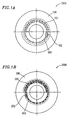
- the optical disk media according to Example 1 are classified into two types, i.e., a reproduction-only type and a recordable type. Structures of these two types of optical disk media are respectively shown in Figures 1A and 1B.
- Figure 1A illustrates an optical disk medium 1000 of a reproduction-only type.
- the optical disk medium 1000 includes a substrate 100 with information marks 101 and synch marks 102 provided along a spiral track center line 103 .
- the information marks 101 and synch marks 102 are respective concave and convex formed by pits and spaces.
- the track center line 103 as described herein does not actually exist as a line on the disk surface as shown in Figure 1A, rather it is virtually depicted. In other words, the track center line 103 runs through the center of a group of spirally formed information pits.
- FIG. 1B illustrates an optical disk medium 2000 of a recordable type.
- the optical disk medium 2000 includes a substrate 200 with a spiral track groove 203 .
- Information marks 201 and synch marks 202 are included in the track groove 203 .
- on the track groove 203 there is a preformed recording layer in which information can be written or rewritten (hereinafter, "record” is used instead of “write” or “rewrite”), and optical characteristics of the recording layer, such as a reflection coefficient, are changed by photothermal means, as in the case of a phase change film.
- the optical disk medium 1000 of a type shown in Figure 1A and the optical disk medium 2000 of a type shown in Figure 1B are characterized in that information preformed on the optical disk medium 1000 and information to be recorded on the optical disk medium 2000 use the same recording form, i.e., format.
- the format as described herein means a common standard regarding recording and reproduction procedures, such as modulation and demodulation methods (e.g., 8-16 modulation for DVD applications), an error correction method, etc.
- modulation and demodulation methods e.g., 8-16 modulation for DVD applications
- an error correction method etc.
- Example 1 of the present invention as shown in Figures 1A and 1B, the polarity of a spiral track provided in the optical disk medium of a reproduction-only type is opposite the polarity of the spiral track provided in the optical disk medium of a recordable type.
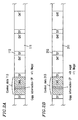
- Figures 2A and 2B schematically illustrate structural examples of information groups formed or recorded on the optical disk media 1000 and 2000 according to a prescribed format.
- the aforementioned information groups include: user data DAT111 or DAT211 (respectively corresponding to the information mark 101 of Figure 1A and the information mark 201 of Figure 1B ) in which normal data (e.g., a digital image, etc.) is formed or recorded; control data CNTL113 or CNTL213 in which management information or the like is formed or recorded; and synch marks 112 or 212 (respectively corresponding to the synch mark 102 of Figure 1A and the synch mark 202 of Figure 1B ).
- copy information CP is included in control data CNTL113 and CNTL213.
- the information provider supplies a receiver with digital TV images via a communication line or the like
- the information provider sends, according to a payment, information representing whether or not recording is permitted to the receiver.
- information representing illegality is recorded on each optical disk medium 2000 produced by coping information on the optical disk medium 1000 bit-by-bit, whereby reproducing information copied to the optical disk medium 2000 is prohibited.
- the reproduction-only optical disk medium 1000 prestores the information representing "illegality", any information stored on this reproduction-only optical disk medium 1000 can be prohibited from being reproduced. However, in the case of reproducing information on an optical disk medium, when the optical disk medium can be identified as being either a reproduction-only type or arecordable type, the information representing "illegality" stored on the reproduction-only optical disk medium 1000 can be ignored so as to reproduce other information stored thereon.
- Example 1 by providing spiral tracks in the optical disk medium of a reproduction-only type and the optical disk medium of a recordable type such that directions of the spiral tracks are opposed to each other, it is possible to identify both types of optical disk media. An identification method will be described in detail below.
- FIG 3 is a block diagram of an optical disk apparatus 3000 according to Example 2 of the present invention.
- an optical disk medium 1 is placed so as to be rotated along a prescribed direction by a disk motor 10.
- the optical disk medium 1000 shown in Figure 1A or the optical disk medium 2000 shown in Figure 1B is used as the optical disk medium 1.
- An optical head 2 reads information formed or recorded on the optical disk medium 1 , and an information reproduction section 3 reproduces information data according to a reproduction signal obtained from the optical disk medium 1 .
- the information reproduction section 3 includes, for example, a signal binarizing circuit and a PLL circuit (not shown).
- the information reproducing section 3 transforms the reproduction signal into a binary pulse signal, and then creates a synchronizing clock so as to create synchronized information data using the synchronizing clock.
- a disk type identification section 6 identifies a direction of a spiral track provided on the optical disk medium 1 so as to identify whether the optical disk medium 1 is a reproduction-only type or a recordable type. An example of a spiral direction detection method will be described with reference to Figures 1A through 4B.
- the synch marks (denoted by SY in the figures) 112 or 212 are inserted every other data block based on the format.
- a synch mark as described herein is used for tracking down the beginning of data, i.e., the synch mark is used for indicating a boundary between data blocks and realizing data synchronization.
- a code which cannot exist in normal data is used as the synch mark.
- 8-16 modulated normal data is limited to a code length of 3T to 11T (T: channel clock length).
- the optical disk medium 1 includes a (pit) mark having a length of 14T and (space) marks which are provided before and after the (pit) mark and have different lengths (3T and 5T).
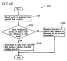
- a synch mark step S101 shown in Figure 4C
- step S102 by sensing the order in which the marks adjacent the synch mark have been detected, it is possible to identify a spiral direction of the optical disk medium 1 , so that the type of the optical disk medium 1 can be identified.
- a spiral track formed on the optical disk medium 2000 of a recordable type has a direction opposite to that of the spiral track formed on the optical disk medium 1000 of a reproduction-only type. Accordingly, in the case of recording information on the optical disk medium 2000 of a recordable type, the disk motor is naturally required to rotate in an opposite way with respect to the case of reproducing information on the optical disk medium 1000 of a reproduction-only type. The same applies to the case of reproducing information on the optical disk medium 2000 .
- a reproduction direction of the information on the optical disk medium 2000 is opposite to a reproduction direction of the information on the optical disk medium 1000.
- information is reproduced in the order of 3T, 14T and 5T in the proper manner, information is reproduced in the order of 5T, 14T and 3T, and thus the optical disk medium 1 is determined to be the optical disk medium 2000 .
- a rotation direction of the optical disk medium 1 is reversed (step S103 shown in Figure 4C ).
- information is reproduced in the order of 3T, 14T and 5T, information is further read from the optical disk medium 1 without changing the rotation direction of the optical disk medium 1 (step S104).
- a signal reproduction direction i.e., a spiral direction can be found, and thus the type of the optical disk medium 1 can be identified.
- the illegal copy detection method is performed after the type (spiral direction) of the disk is determined in the above-described manner.
- a polarity switching signal POL ( Figure 3 ) is sent to a polarity switching section 9 .
- the polarity switching section 9 is provided between the disk motor 10 and a motor drive section 8 which supplies a drive current to the disk motor 10 .
- the polarity switching section 9 switches a direction of the current supplied to the disk motor 10 according to the polarity switching signal POL .
- the polarity switching section 9 performs a crossbar operation according to the signal. When the current direction is switched by this operation, the rotation of the disk motor 10 is reversed.
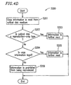
- the information reproduction section 3 When information is read along the proper direction by an optical head, the information reproduction section 3 performs an information reproduction process based on the format shown in Figures 2A or 2B. During this process, copy information CP is reproduced (step S201 shown in Figure 4D ).
- step S202 whether the optical disk medium 1 is the optical disk medium 1000 of a reproduction-only type or the optical disk medium 2000 of a recordable type is determined based on the results of the method depicted in the flowchart of Figure 4C (step S202).
- the optical disk medium 1 is the optical disk medium 1000 of a reproduction-only type
- a gate 5 determines, based on the output C from copy information determination section 4 , whether or not to output a reproduction signal SDATA.
- Example 2 of the present invention by preforming information representing a history that information has been illegally copied on the optical disk medium 1000 and also forming a spiral track on the optical disk medium 2000 of a recordable type so as to have a direction opposite to that of a spiral track formed on the optical disk medium 1000 of a reproduction-only type, it is possible to accurately identify both type of the optical disk media, and it is also possible to readily identify illegally copied information.
- Example 2 of the present invention even if information on the optical disk medium 1000 of a reproduction-only type is copied bit-by-bit on the optical disk medium 2000 of a recordable type, which has the same format as the optical disk medium 1000, the illegality of the disk can be readily identified and reproducing the illegal disk can be prohibited, whereby copyright protection can be achieved.
- Example 2 of the present invention includes any format for a disk of a recordable type which appears to a reproduction-only optical disk drive as if the format is practically the same as a format for a disk of a reproduction-only type.
- the disk of a recordable type has a physical address in addition to the format for a disk of a reproduction-only type.
- the physical address refers to address information preformed on the disk of a recordable type.
- the physical address is used as an index for recording information.
- the format for the disk of a recordable type is different from that for the disk of a reproduction-only type.
- the format for the disk of a recordable type can be substantially same as that for the disk of a reproduction-only type.
- both types of disks which have their respective spiral tracks opposing each other, have the same format.
- one of the reasons why both types of the disks should have the same format is that, in the case where the disk of a recordable type is used as an authoring disk, if the disk of a recordable type does not have the same format as that of the disk of a reproduction-only type which is a disk to be a final product, as described above, system performance cannot be satisfactorily verified.
- Example 2 it is not conceivable that reversing a rotation direction of an optical disk affects system performance.
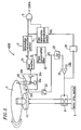
- FIG. 5 is a block diagram of an optical disk apparatus 4000 according to Example 3 of the present invention.
- components similar to those of the optical disk apparatus 3000 shown in Figure 3 are denoted by similar reference numerals.
- an optical disk medium 1 an information reproduction section 3, a copy information determination section 4, a gate 5, a motor drive section 8, a polarity switching section 9 , and a disk motor 10 have the same function as their corresponding components of the optical disk apparatus 3000 shown in Figure 3 .
- an optical head 20 includes an object lens 20b which focuses a laser beam emitted by a laser source 20a on the optical disk medium 1, and a photodetector 20c which transforms a reflection beam from the optical disk medium 1 into an electric signal group.
- a head amplifier 21 creates an information reproduction signal HF and a tracking error signal TE from the electric signal group.
- the tracking error signal TE is input to a phase compensation filter 22, and the phase compensation filter 22 outputs a tracking control signal TC.
- the tracking control signal TC is fed back through a drive amplifier 23 to a tracking actuator 20d of the optical head 20, thereby performing tracking control.
- Example 3 of the present invention is characterized in that the type of the optical disk medium 1 is identified by identifying a spiral direction of the optical disk medium 1 based on the tracking control signal TC.
- the location of a focused laser beam with which the optical disk medium 1 is irradiated by the object lens 20b is controlled so as to follow a track formed on the optical disk medium 1 .
- the aforementioned focused laser beam moves toward an outer circumference or an inner circumference of the optical disk medium 1 .
- Whether the focused laser beam moves toward the outer circumference or the inner circumference of the optical disk medium 1 depends on a spiral direction of the track on the optical disk medium 1 .
- the spiral direction of the optical disk medium 1 can be identified, thereby identifying the type of optical disk medium 1.
- a specific example of methods for detecting the moving direction of the focused laser beam uses an optical element which detects displacement of the tracking actuator 20d .
- the polarity of an accumulated error of a tracking error signal is detected using an integrator circuit 24 and a comparator 25.
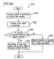
- a method for detecting the spiral direction of the optical disk medium 1 from the moving direction of the focused laser beam will be described with reference to Figure 6A and a flowchart 4100 shown in Figure 6B.
- the aforementioned tracking control system is used for feeding back a detected tracking error signal to the tracking actuator 20d (step S301 shown in Figure 6B ).
- the detected tracking error signal is integrated (step S302), and the polarity of the integrated tracking error signal is identified (step S303).
- the tracking actuator 20d includes a movable element on which an object lens is mounted, and a fixed element to which an electromagnetic coil is provided. These two elements are joined by a weak elastic body (e.g., a spring), and thus the tracking actuator 20d has spring-mass system secondary integral characteristics. That is, the tracking actuator 20d has a character of being displaced by a distance corresponding to a value obtained by integrating the tracking error signal TE through the tracking control. In other words, the tracking actuator 20d has the ability to overpower reaction force of a spring using an integrated driving power.
- an integrated output by the integrator circuit 24 exactly corresponds to the displacement of the tracking actuator 20d.
- Figure 6A shows an example of variations in an integrated tracking error signal STE (i.e., the aforementioned integrated output) for each of the cases where the optical disk medium 1 is a reproduction-only type or a recordable type and a rotation direction of the optical disk medium 1 is prescribed.
- STE integrated tracking error signal
- the tracking actuator 20d when reproducing information on the optical disk medium 2000 of a recordable type on which a spiral track is formed along a direction opposite the optical disk medium 1000, the tracking actuator 20d is displaced toward the inner circumference of the disk and the integrated tracking error signal STE varies in a negative direction.
- a spiral direction of the optical disk medium 1 that is, the type of the disk can be identified.
- Example 3 of the present invention as shown in Figure 6A, a threshold -Vth is set on the negative side of an electric potential, and when the integrated tracking error signal STE falls below the threshold -Vth, the comparator 25 is operated, so that a latch 26 ( Figure 5 ) holds a signal from the comparator 25 and supplies a polarity switching signal POL to the polarity switching section 9 and the copy information determination section 4 (step S305 shown in Figure 6B ).
- the spiral direction of the optical disk medium 1 can be identified based on an amount of the integrated tracking error signal TE, thereby further identifying the type of the optical disk medium 1.
- switching a rotation direction of an optical disk medium is automatically performed by an optical disk apparatus.
- a user of the optical disk apparatus may manually switch the rotation direction of the optical disk medium by operating the optical disk apparatus.
- the present invention is applicable not only to an optical disk but also to recording media having any disk shape, such as a magneto-optical disk, a magnetic disk, etc.
- an optical disk of a reproduction-only type and an optical disk of a recordable type have the same format and each type of the disks includes a track thereon, which has a spiral direction opposite the other type of disk, whereby it is possible to readily identify both types of disks. It is also possible to identify whether or not information has been illegally recorded on an optical disk.
Landscapes
- Engineering & Computer Science (AREA)
- Signal Processing (AREA)
- Computer Security & Cryptography (AREA)
- Optical Recording Or Reproduction (AREA)
- Signal Processing For Digital Recording And Reproducing (AREA)
- Optical Record Carriers And Manufacture Thereof (AREA)
Abstract
Description
Claims (17)
- A reproduction-only disk medium comprising preformed first information, wherein:the first information is formed in the same format as second information recorded on a prescribed recordable disk medium; anda direction along which the first information is formed on the reproduction-only disk medium is opposite to a direction along which the second information is recorded on the prescribed recordable disk medium.
- A reproduction-only disk medium according to claim 1, wherein third information, which represents that the first information is illegal, is preformed.
- A reproduction-only disk medium according to claim 1, wherein:the first information is formed according to a prescribed modulation rule;fourth information, which has a first mark having a code length other than that created according to the prescribed modulation rule, is preformed on the reproduction-only disk medium; anda second mark and a third mark respectively having a different prescribed code length are formed so as to be adjacent the first mark.
- A reproduction-only disk medium according to claim 1, wherein:the first information is formed along a first spiral direction of a spiral first track on the reproduction-only disk medium; andthe first spiral direction is opposite to a second spiral direction of a spiral second track on the prescribed recordable disk medium on which the second information is recorded.
- A recordable disk medium on which first information is recorded, wherein:the first information is recorded in the same format as second information preformed on a prescribed reproduction-only disk medium; anda direction along which the first information is recorded on the recordable disk medium is opposite to a direction along which the second information is formed on the prescribed reproduction-only disk medium.
- A recordable disk medium according to claim 5, comprising a region in which third information is recorded representing whether the first information is legal or illegal.
- A recordable disk medium according to claim 5, wherein:the first information is recorded according to a prescribed modulation rule;fourth information, which has a first mark having a code length other than that created according to the prescribed modulation rule, is recorded on the recordable disk medium; anda second mark and a third mark respectively having a different prescribed code length are recorded so as to be adjacent the first mark.
- A recordable disk medium according to claim 5, wherein:the first information is recorded along a first spiral direction of a spiral first track on the recordable disk medium; andthe first spiral direction is opposite to a second spiral direction of a spiral second track on the prescribed reproduction-only disk medium on which the second information is formed.
- An optical disk apparatus reproducing at least first information or second information from a reproduction-only disk medium on which the first information is preformed or a recordable disk medium on which the second information is recorded, the optical disk apparatus comprising:a motor for rotating the reproduction-only disk medium or the recordable disk medium; anda motor drive section for controlling the motor,wherein a rotation direction during reproduction of the reproduction-only disk medium is different from a rotation direction during reproduction of the recordable disk medium.
- An optical disk apparatus according to claim 9, wherein:a first spiral direction of a spiral first track on the reproduction-only disk medium on which the first information is formed is opposite to a second spiral direction of a spiral second track on the recordable disk medium on which the second information is recorded;the optical disk apparatus further comprises a disk type identification section for identifying the reproduction-only disk medium and the recordable disk medium from the first spiral direction or the second spiral direction.
- An optical disk apparatus according to claim 10, further comprising a rotation direction switching section for switching a rotation direction of the motor according to the first spiral direction or the second spiral direction.
- An optical disk apparatus according to claim 9, wherein:the reproduction-only disk medium includes preformed third information which represents that the first information is illegal; andduring reproduction of the reproduction-only disk medium, the third information is ignored by the optical disk apparatus.
- An optical disk apparatus according to claim 10, wherein:the reproduction-only disk medium includes preformed fourth information representing the first spiral direction;the recordable disk medium includes preformed fifth information representing the second spiral direction; anda direction identification section identifies the first spiral direction and the second spiral direction based on the fourth information and the fifth information.
- A disk medium identification method for identifying a reproduction-only disk medium including a plurality of pits preformed along a first spiral direction of a spiral first track and a recordable disk medium on which information can be recorded along a second spiral direction of a spiral second track opposite to the first spiral direction, the method comprising the steps of:performing tracking control by rotating a prescribed disk along a prescribed direction;integrating a tracking error signal created when performing the tracking control; andidentifying the reproduction-only disk medium and the recordable disk medium according to a polarity of the integrated tracking error signal.
- A disk medium identification method for identifying a reproduction-only disk medium including a plurality of pits preformed along a first spiral direction of a spiral first track and a recordable disk medium on which information can be recorded along a second spiral direction of a spiral second track opposite to the first spiral direction, the method comprising the steps of:detecting a first signal from a prescribed disk when the prescribed disk is rotated along a prescribed direction; andidentifying the reproduction-only disk medium and the recordable disk medium based on the first signal.
- A disk medium identification method according to claim 15, wherein the first signal includes at least a second signal having a first code length, a third signal having a second code length, and a fourth signal having a third code length, the code lengths being different from one another.
- A disk medium identification method according to claim 16, identifying the reproduction-only disk medium and the recordable disk medium according to at least an order in which the second signal, the third signal, and the fourth signal are reproduced.
Applications Claiming Priority (3)
| Application Number | Priority Date | Filing Date | Title |
|---|---|---|---|
| JP24834799 | 1999-09-02 | ||
| JP24834799 | 1999-09-02 | ||
| PCT/JP2000/005944 WO2001018798A1 (en) | 1999-09-02 | 2000-08-31 | Optical disk medium and optical disk identification method and optical disk device |
Publications (2)
| Publication Number | Publication Date |
|---|---|
| EP1213710A1 true EP1213710A1 (en) | 2002-06-12 |
| EP1213710A4 EP1213710A4 (en) | 2007-01-10 |
Family
ID=17176751
Family Applications (1)
| Application Number | Title | Priority Date | Filing Date |
|---|---|---|---|
| EP00956866A Withdrawn EP1213710A4 (en) | 1999-09-02 | 2000-08-31 | OPTICAL DISC MEDIUM, OPTICAL DISC IDENTIFICATION METHOD, AND OPTICAL DISC DEVICE |
Country Status (5)
| Country | Link |
|---|---|
| US (1) | US6850478B1 (en) |
| EP (1) | EP1213710A4 (en) |
| KR (2) | KR100491782B1 (en) |
| CN (1) | CN1273969C (en) |
| WO (1) | WO2001018798A1 (en) |
Cited By (1)
| Publication number | Priority date | Publication date | Assignee | Title |
|---|---|---|---|---|
| EP2381443A1 (en) * | 2010-04-21 | 2011-10-26 | Thomson Licensing | Optical disc with protection code, method for obtaining the protection code and respective apparatus for reading of data |
Families Citing this family (8)
| Publication number | Priority date | Publication date | Assignee | Title |
|---|---|---|---|---|
| US7126906B2 (en) * | 2000-12-21 | 2006-10-24 | Hitachi Maxell, Ltd. | Optical record carrier, drive unit, data updating method and software version-up method |
| US7327648B2 (en) * | 2003-11-19 | 2008-02-05 | Warner Bros. Home Entertainment Inc. | Player with rotational control for double-sided optical discs |
| US20050105457A1 (en) * | 2003-11-19 | 2005-05-19 | Cookson Christopher J. | Double-sided optical disc with means for indicating its proper direction of rotation |
| US7512048B2 (en) * | 2003-11-20 | 2009-03-31 | Warner Bros. Entertainment Inc. | Method and apparatus for reading optical discs having different configurations |
| US20050111334A1 (en) * | 2003-11-20 | 2005-05-26 | Cookson Christopher J. | Method and apparatus for reading data from an optical disc in a reverse direction |
| US20090290468A1 (en) * | 2004-12-20 | 2009-11-26 | Koninklijke Philips Electronics, N.V. | Information reproducing method |
| TWI263200B (en) * | 2005-08-02 | 2006-10-01 | Asustek Comp Inc | Accelerating apparatus for a disc drive |
| JP2009134784A (en) * | 2007-11-29 | 2009-06-18 | Tdk Corp | Multilayer recording medium and optical recording/reproducing method |
Family Cites Families (12)
| Publication number | Priority date | Publication date | Assignee | Title |
|---|---|---|---|---|
| US5255262A (en) * | 1991-06-04 | 1993-10-19 | International Business Machines Corporation | Multiple data surface optical data storage system with transmissive data surfaces |
| JP3025561B2 (en) * | 1991-09-06 | 2000-03-27 | 株式会社日立製作所 | Optical disk drive |
| CN1126078C (en) * | 1994-04-18 | 2003-10-29 | 松下电器产业株式会社 | Method and device for preventing illegal copying or illegal installation of information on an optical recording medium |
| JP3447812B2 (en) * | 1994-07-29 | 2003-09-16 | 株式会社東芝 | Cartridge for accommodating disks and disk device handling this cartridge |
| AU3468395A (en) * | 1994-09-20 | 1996-04-09 | Paralight Laser Technologies Inc. | Multiple-layer optical disc and apparatus |
| EP0715301B1 (en) * | 1994-11-30 | 2000-01-19 | Sony Corporation | Data recording media and recording/reproduction thereof |
| MY112755A (en) * | 1995-06-06 | 2001-08-30 | Sony Corp | Information data reproducing system, reproducing apparatus, reproducing method, data forming apparatus and data record medium |
| EP0751513B1 (en) * | 1995-06-29 | 2002-03-27 | Matsushita Electric Industrial Co., Ltd. | Optical medium and apparatus for recording and reproducing the same |
| JPH0955016A (en) * | 1995-08-14 | 1997-02-25 | Sony Corp | Disc-shaped recording medium, data reproducing method and device |
| EP0856186B1 (en) * | 1995-10-19 | 2000-06-28 | Matsushita Electric Industrial Co., Ltd. | Information storage medium, information reproducing method, and information reproducing apparatus |
| JP3063613B2 (en) * | 1996-03-25 | 2000-07-12 | 三菱電機株式会社 | Optical disk medium and optical disk device |
| JP4162294B2 (en) * | 1998-07-03 | 2008-10-08 | パイオニア株式会社 | Information reproducing apparatus having copy restriction function |
-
2000
- 2000-08-31 EP EP00956866A patent/EP1213710A4/en not_active Withdrawn
- 2000-08-31 US US10/069,638 patent/US6850478B1/en not_active Expired - Fee Related
- 2000-08-31 WO PCT/JP2000/005944 patent/WO2001018798A1/en not_active Ceased
- 2000-08-31 KR KR10-2004-7010254A patent/KR100491782B1/en not_active Expired - Fee Related
- 2000-08-31 CN CNB008124094A patent/CN1273969C/en not_active Expired - Fee Related
- 2000-08-31 KR KR10-2002-7002860A patent/KR100470521B1/en not_active Expired - Fee Related
Cited By (3)
| Publication number | Priority date | Publication date | Assignee | Title |
|---|---|---|---|---|
| EP2381443A1 (en) * | 2010-04-21 | 2011-10-26 | Thomson Licensing | Optical disc with protection code, method for obtaining the protection code and respective apparatus for reading of data |
| EP2381441A1 (en) * | 2010-04-21 | 2011-10-26 | Thomson Licensing | Optical disc with protection code, method for obtaining the protection code and respective apparatus for reading of data. |
| US8264925B2 (en) | 2010-04-21 | 2012-09-11 | Thomson Licensing | Optical disc with protection code, method for obtaining the protection code and respective apparatus for reading of data |
Also Published As
| Publication number | Publication date |
|---|---|
| WO2001018798A1 (en) | 2001-03-15 |
| KR100491782B1 (en) | 2005-05-30 |
| US6850478B1 (en) | 2005-02-01 |
| KR100470521B1 (en) | 2005-03-10 |
| CN1273969C (en) | 2006-09-06 |
| KR20020037352A (en) | 2002-05-18 |
| EP1213710A4 (en) | 2007-01-10 |
| CN1372684A (en) | 2002-10-02 |
| KR20040075040A (en) | 2004-08-26 |
Similar Documents
| Publication | Publication Date | Title |
|---|---|---|
| US6791937B2 (en) | Recordable optical disk | |
| JP2005310379A (en) | Recording medium with restricted playback feature and apparatus and methods for thus forming, recording on and reproducing from the recording medium | |
| US6850478B1 (en) | Optical disk medium and optical disk indentification method and optical disk device | |
| EP1204100B1 (en) | Recordable optical disk | |
| EP1586094B1 (en) | Method of managing copy protection information of a recording medium, recording medium with copy protection information for contents recorded thereon, and reproducing method for the recording medium | |
| US7345979B2 (en) | Storage medium storing copy protection data in burst cutting area using the on-off keying modulation method | |
| JPWO2001018798A1 (en) | Optical disc medium, optical disc identification method, and optical disc device | |
| JP2001084704A (en) | Optical-disk recording medium and manufacture of the optical-disk recording medium |
Legal Events
| Date | Code | Title | Description |
|---|---|---|---|
| PUAI | Public reference made under article 153(3) epc to a published international application that has entered the european phase |
Free format text: ORIGINAL CODE: 0009012 |
|
| 17P | Request for examination filed |
Effective date: 20020328 |
|
| AK | Designated contracting states |
Kind code of ref document: A1 Designated state(s): AT BE CH CY DE DK ES FI FR GB GR IE IT LI LU MC NL PT SE |
|
| AX | Request for extension of the european patent |
Free format text: AL;LT;LV;MK;RO;SI |
|
| RBV | Designated contracting states (corrected) |
Designated state(s): DE FR GB |
|
| A4 | Supplementary search report drawn up and despatched |
Effective date: 20061208 |
|
| RIC1 | Information provided on ipc code assigned before grant |
Ipc: G11B 7/00 20060101AFI20061204BHEP |
|
| 17Q | First examination report despatched |
Effective date: 20071016 |
|
| RAP1 | Party data changed (applicant data changed or rights of an application transferred) |
Owner name: PANASONIC CORPORATION |
|
| STAA | Information on the status of an ep patent application or granted ep patent |
Free format text: STATUS: THE APPLICATION IS DEEMED TO BE WITHDRAWN |
|
| 18D | Application deemed to be withdrawn |
Effective date: 20090925 |