EP1213338B1 - Methods for preparing flakes - Google Patents
Methods for preparing flakes Download PDFInfo
- Publication number
- EP1213338B1 EP1213338B1 EP01126428A EP01126428A EP1213338B1 EP 1213338 B1 EP1213338 B1 EP 1213338B1 EP 01126428 A EP01126428 A EP 01126428A EP 01126428 A EP01126428 A EP 01126428A EP 1213338 B1 EP1213338 B1 EP 1213338B1
- Authority
- EP
- European Patent Office
- Prior art keywords
- lamina
- pack
- layer
- platelets
- laminae
- Prior art date
- Legal status (The legal status is an assumption and is not a legal conclusion. Google has not performed a legal analysis and makes no representation as to the accuracy of the status listed.)
- Expired - Lifetime
Links
Images


Classifications
-
- C—CHEMISTRY; METALLURGY
- C09—DYES; PAINTS; POLISHES; NATURAL RESINS; ADHESIVES; COMPOSITIONS NOT OTHERWISE PROVIDED FOR; APPLICATIONS OF MATERIALS NOT OTHERWISE PROVIDED FOR
- C09C—TREATMENT OF INORGANIC MATERIALS, OTHER THAN FIBROUS FILLERS, TO ENHANCE THEIR PIGMENTING OR FILLING PROPERTIES ; PREPARATION OF CARBON BLACK ; PREPARATION OF INORGANIC MATERIALS WHICH ARE NO SINGLE CHEMICAL COMPOUNDS AND WHICH ARE MAINLY USED AS PIGMENTS OR FILLERS
- C09C3/00—Treatment in general of inorganic materials, other than fibrous fillers, to enhance their pigmenting or filling properties
- C09C3/04—Physical treatment, e.g. grinding, treatment with ultrasonic vibrations
-
- C—CHEMISTRY; METALLURGY
- C09—DYES; PAINTS; POLISHES; NATURAL RESINS; ADHESIVES; COMPOSITIONS NOT OTHERWISE PROVIDED FOR; APPLICATIONS OF MATERIALS NOT OTHERWISE PROVIDED FOR
- C09K—MATERIALS FOR MISCELLANEOUS APPLICATIONS, NOT PROVIDED FOR ELSEWHERE
- C09K19/00—Liquid crystal materials
- C09K19/04—Liquid crystal materials characterised by the chemical structure of the liquid crystal components, e.g. by a specific unit
- C09K19/38—Polymers
-
- C—CHEMISTRY; METALLURGY
- C09—DYES; PAINTS; POLISHES; NATURAL RESINS; ADHESIVES; COMPOSITIONS NOT OTHERWISE PROVIDED FOR; APPLICATIONS OF MATERIALS NOT OTHERWISE PROVIDED FOR
- C09B—ORGANIC DYES OR CLOSELY-RELATED COMPOUNDS FOR PRODUCING DYES, e.g. PIGMENTS; MORDANTS; LAKES
- C09B67/00—Influencing the physical, e.g. the dyeing or printing properties of dyestuffs without chemical reactions, e.g. by treating with solvents grinding or grinding assistants, coating of pigments or dyes; Process features in the making of dyestuff preparations; Dyestuff preparations of a special physical nature, e.g. tablets, films
- C09B67/006—Preparation of organic pigments
- C09B67/0061—Preparation of organic pigments by grinding a dyed resin
-
- C—CHEMISTRY; METALLURGY
- C09—DYES; PAINTS; POLISHES; NATURAL RESINS; ADHESIVES; COMPOSITIONS NOT OTHERWISE PROVIDED FOR; APPLICATIONS OF MATERIALS NOT OTHERWISE PROVIDED FOR
- C09B—ORGANIC DYES OR CLOSELY-RELATED COMPOUNDS FOR PRODUCING DYES, e.g. PIGMENTS; MORDANTS; LAKES
- C09B67/00—Influencing the physical, e.g. the dyeing or printing properties of dyestuffs without chemical reactions, e.g. by treating with solvents grinding or grinding assistants, coating of pigments or dyes; Process features in the making of dyestuff preparations; Dyestuff preparations of a special physical nature, e.g. tablets, films
- C09B67/0098—Organic pigments exhibiting interference colours, e.g. nacrous pigments
-
- C—CHEMISTRY; METALLURGY
- C09—DYES; PAINTS; POLISHES; NATURAL RESINS; ADHESIVES; COMPOSITIONS NOT OTHERWISE PROVIDED FOR; APPLICATIONS OF MATERIALS NOT OTHERWISE PROVIDED FOR
- C09K—MATERIALS FOR MISCELLANEOUS APPLICATIONS, NOT PROVIDED FOR ELSEWHERE
- C09K19/00—Liquid crystal materials
- C09K19/04—Liquid crystal materials characterised by the chemical structure of the liquid crystal components, e.g. by a specific unit
- C09K19/38—Polymers
- C09K19/3833—Polymers with mesogenic groups in the side chain
- C09K19/3842—Polyvinyl derivatives
- C09K19/3852—Poly(meth)acrylate derivatives
- C09K19/3866—Poly(meth)acrylate derivatives containing steroid groups
-
- C—CHEMISTRY; METALLURGY
- C09—DYES; PAINTS; POLISHES; NATURAL RESINS; ADHESIVES; COMPOSITIONS NOT OTHERWISE PROVIDED FOR; APPLICATIONS OF MATERIALS NOT OTHERWISE PROVIDED FOR
- C09K—MATERIALS FOR MISCELLANEOUS APPLICATIONS, NOT PROVIDED FOR ELSEWHERE
- C09K19/00—Liquid crystal materials
- C09K19/52—Liquid crystal materials characterised by components which are not liquid crystals, e.g. additives with special physical aspect: solvents, solid particles
- C09K19/58—Dopants or charge transfer agents
- C09K19/586—Optically active dopants; chiral dopants
Definitions
- the invention relates to a method for producing platelets a thickness of 0.2 - 1000 ⁇ m and a diameter of 0.5-10,000 ⁇ m.
- Such platelets come naturally as scales, fish silver or mica platelets before and are as such or in surface-modified form used as effect pigments.
- artificial effect pigments are known, for example consist of thin platelets of cholesteric liquid crystals.
- Such platelets are also found, for example, as rheological additives widely used.
- the material layer of the carrier material not be pulled off over the whole area without tearing, but it must be subjected to an abrasive process. specially This process step is used for thin layers below 10 ⁇ m costly and with wear problems of the carrier material connected, especially if it is as a carrier material general terephthalate film (DE 196 18 566 A1, DE 197 07 805 A1). To avoid this problem, it is known Apply release agent to the carrier material before that Material or the materials that make up the interference pigment be applied. This is a great way to when brittle materials form the interference pigment. However, there are significant problems when it comes to Materials with high elongation at break and low tensile strength is. On the one hand, they are extremely difficult in To transfer fragments by compressed air or suction can be removed from the carrier material, on the other hand are they not firm enough to be seen as a film from Carrier to be released.
- No. 5,364,557 discloses the production of thin cholesteric platelets by applying a cholesteric layer on a carrier material, for example on a film, by means of an applicator consisting of a doctor blade or a roller applicator.
- a carrier material for example on a film
- an applicator consisting of a doctor blade or a roller applicator.
- the application takes place above the melting or glass temperature of the material.
- the material is then removed from the substrate below the melting or glass temperature with an air jet, which may contain an abrasive powder, or with a scraper.
- the transfer to another carrier material is described as a special embodiment.
- the creation of layers consisting of substances with different properties is disclosed.
- double layers consisting of left and right helical material which deliver platelets during the shredding process, which consist of a left and right helical layer and do not disintegrate into further layers during the shredding process.
- All of the procedures disclosed in US Pat. No. 5,364,557 lead to a single layer, optionally made up of sublayers, from which plates are obtained by breaking, which have the thickness of the layer subjected to the milling process.
- crosslinked cholesteric is produced Platelets by printing on a carrier with cholesteric Material, by crosslinking and then removing of the printed, cross-linked material.
- the one ultimately obtained corresponds to cholesteric platelets.
- DE 197 57 699 discloses a process for producing platelet-shaped, cholesteric multilayer interference pigments, characterized by the Layer sequences A1-B-A2, whereby A1 and A2 can be different, however comprise at least one cholesteric layer and B for a separating layer Intermediate layer stands, the light that transmits the layers A1 and A2 partially or completely absorbed.
- the multi-layer pigments disclosed have one Diameters from 5 to 500 ⁇ m.
- the layer thickness of each cholesteric Layers A1 or A2 are 0.5 to 20 ⁇ m, while the layer thickness of each single layer B is 0.2 to 5 microns.
- the object of the invention is therefore to provide a method that makes it possible even from materials with high elongation at break and low tensile strength without the problems mentioned Small plates with a thickness of 0.1-1000 ⁇ m and a diameter of 0.5-10 000 ⁇ m.
- a Material to be processed in flowable or gaseous form Condition applied to a carrier, solidified, from removed from the carrier and subjected to a crushing or grinding process is characterized in that the material on the carrier is applied one above the other in such a way that after application there is a layer package which is perpendicular to the cross section individual layers with a thickness between 0.2 - Contains 1000 ⁇ m, the strength of the layer package parallel to the course of the layer is greater than perpendicular to the course of the layer, and this layer package after detachment from the Carrier is treated so that the material in individual layers disintegrates and the individual layers to a particle size of 0.5 - 10000 ⁇ m can be crushed.
- a layer package is preferably obtained in that unconsolidated, material to be processed into platelets, first in is usually applied to a carrier and solidified and then unconsolidated onto this solidified material material to be processed into platelets and is solidified without welding or blocking the individual layers of material with one another comes.
- Process steps suitable for this are, for example applying and polymerizing or crosslinking polymerizable or crosslinkable materials onto an already polymerized one or cross-linked layer or applying one Melt on solidified, cold material.
- the layer package is used using a Release agent generated. This is done on a solidified material layer before applying an unconsolidated layer of material a release agent applied.
- the release agent can be applied between each individual layer or after a certain one Number of layers are done.
- the release agent becomes platelet according to the number of Layers (sub-layers), which after crushing a multilayer Form platelets, applied.
- Sub-layers which after crushing a multilayer Form platelets, applied.
- a single layer in the sense of the present invention can therefore quite how also known from the prior art, from several sub-layers, that are inseparable from each other.
- the layer package is preferably made two or more times Applying and solidifying the material to be processed, which forms a single layer.
- any material is suitable that at the solidification temperature of the to be applied Material is solid.
- metals like iron, Steel, alloyed steels, brass, chrome, copper or plastics such as saturated polyester (PET), polyethylene (PE), polypropylene (PP), polystyrene (PS), cross-linked unsaturated polyester, polytetrafluoroethylene (Teflon), polyimides and polyamides as well as inorganic oxidic and non-oxidic materials such as porcelain, Silicon carbide, tungsten carbide, boron carbide, silicon nitride, Mixed ceramics, granite and glass or combinations of these materials in the form of coated materials or made from them Composites.
- Plate, cylindrical, tubular or band-shaped can be used as carriers Body can be chosen. Your surfaces can be rough, ground, polished, surface coated and / or with a separating layer be provided. It is preferably cylindrical Body or body that may be conical or are parabolic.
- Materials that are used in the method according to the invention can be cross-linkable materials or substances made from the liquid phase can be converted into a solid phase, be it by solidifying a melt or by evaporation of a solvent, be it by crystallization or a Crosslinking reaction.
- polyesters saturated and unsaturated Polyester, epoxies, vinyl esters, vinyl ethers, polyurethanes, Silanes, siloxanes, silanolates, water glass, silicic acid esters, liquid crystalline, polymerizable or crosslinkable aromatic, cycloaliphatic or heterocyclic compounds such as Epoxides with the amino, hydroxy or anhydride components, vinyl esters, Vinyl ether, isocyanates as such or with the corresponding HO components in monomeric or oligomeric form, Silanes or siloxanes.
- They are preferably polymerizable, crosslinkable, liquid crystalline, nematic, smectic, chiral nematic and chiral smectic materials.
- the materials a cholesteric phase.
- the materials can be pure or in combination with others Substances such as excipients or active ingredients are used become.
- Auxiliaries are e.g. Fillers, dyes, Pigments or initiators for radical or ionic polymerizations, for polyadditions, condensations or for hydrosilylations.
- the active ingredients can be dissolved or as a second phase in the material available. It is e.g. pharmaceuticals, herbicides or pesticides.
- the materials can also be in dispersed liquids included, e.g. low molecular weight liquid crystalline substances, which in the usual way e.g. by applying electrical fields in the tiles can be switched.
- dispersed liquids included e.g. low molecular weight liquid crystalline substances, which in the usual way e.g. by applying electrical fields in the tiles can be switched.
- the second phase can be in the matrix of the material to be used even before the method according to the invention is carried out or it can be present during the process according to the invention arise through phase separation.
- filming dispersions, suspensions, Powder coatings or comparable systems as well as by sputtering or evaporable materials as starting materials in the inventive methods are used.
- these are polymerizable, polyaddable, hydrosilylatable, polycondensable, crosslinkable Fabrics, meltable resins, thermoplastics, by evaporation of Solvents, suspensions and films which can be converted into films mixtures which can be converted into two-phase systems by polymerization, any auxiliary substances such as photoinitiators, peroxides, Contain UV absorbers, dyes or pigments.
- the layer package can be constructed with one or more of the materials mentioned. Prerequisite for successful Is to carry out the method according to the invention, that the strength of the layer package parallel to the course of the layer is larger than perpendicular to the layers.
- Release agents can be selected from the group of compounds Silicones, also surfactants, polyethers, polyvinyl alcohol (PVA), finely divided silica (HDK), talc, Teflon powder, graphite, Molybdenum sulfide, mica powder and metal flakes (e.g. Al or Brass) can be used.
- the release properties of the release agent can be effective immediately after the layer package has been removed from the support or, for example, can be effective in a subsequent calcination step in the case of a layer package made of inorganic material. In the case of a layer package containing organic separating layers, this can be done, for example, by calcining in an oxidizing atmosphere above 150 ° C. or by blowing up a separating layer which, for example, eliminates water, CO 2 or N 2 .
- crosslinkable materials can be used between the individual layers by making the layers of cross-linkable Materials whose separation is initially undesirable, only weakly networked, the layer at which the separation should take place, but is strongly networked.
- the materials can be applied by various methods respectively. Examples are application options by rolling, Squeegees, spraying in liquid form with or without solvent or in the form of powders according to known powder technologies called as well as evaporation and sputtering.
- the order can be done with one or more commissioned works, whereby the material or materials between the commissioned works be converted into the desired solid form must / must. Depending on the material, this is done in a known manner and by drying, polymerizing, crosslinking or cooling.
- the layer packs can optionally be used generated by smoothing elements.
- the materials to be processed into platelets are liquid-crystalline materials, so the Layer structure preferably in the presence of liquid crystals orienting auxiliaries or electrical or magnetic Fields. Corresponding methods are from the prior art known. With such materials, the structure of the Layer packages preferably without the use of a release agent.
- the layer package can also be removed by removal of layers on the side opposite the application respectively.
- the removal is preferably carried out continuously.
- the crushing process can take place, for example, in a pan mill, a ball mill, a pin mill or an air jet mill and the material is then classified.
- the method according to the invention can also be carried out in this way that materials with different properties applied one after the other, with the proviso that these double or Multiple layers the individual layers of the resulting Layer packets, which are the desired ones during the grinding process Deliver tiles with the desired layer sequence.
- the method according to the invention can therefore also be used Realize tiles with layer structure.
- different ones can be Material combinations e.g. B. AB, ABA, ABC etc.
- cholesteric liquid crystals with different ones Get reflection wavelengths or different helicity become.
- Combinations of cholesteric layers with planar oriented nematic layers that are linearly polarized Reflect light, or combinations of cholesteric Layers with homeotropically oriented nematic or smectic layers are possible.
- the platelets produced according to the invention can be further Process steps such as coating with metals and metal oxides are supplied.
- a variant of the method according to the invention can be, for example by modifying that described in DE 42 40 743 A1 Realize procedure.
- DE 42 40 743 A1 becomes the crosslinking reaction of the to be processed into platelets Material between two films, a carrier and cover film executed.
- This process thus becomes the invention Modified procedure that the first, between carrier and Covering film is freed of the cover film and the layer with the carrier film one or more others Coating steps analogous to the coating of the carrier is subjected.
- a layer package produced in this way in the form of a layer stack can be considerably from the carrier peel off better than a single layer.
- Process variant is the carrier film without Release agent or release layer used.
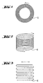
- 1 to 3 are examples of further types of material application for building a layer package, from which platelet can be obtained discontinuously or continuously, shown schematically, the material application continuously or discontinuously.
- the arrows indicate that Direction of the order.
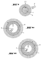
- the application of the material according to FIG. 1 takes place, for example on the outside of a rotating cylinder as a carrier a commissioned work.
- This process is schematic in Fig. 4 a shown.
- the order on the inside is analogous a cylinder as a carrier possible.
- the orbital period of the unsolidified Material on the cylinder larger than that for solidification time required, the solidification can be continuous take place and a roll-shaped layer package is created.
- Layer packets are a ring-shaped layer packet as shown in Fig. 4b.
- the order of the material on the Inside of a cylinder can in the manner already described done, but it can also be followed by a spraying process of leveling the material by centrifugal acceleration respectively.
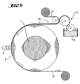
- the material is made from a material reservoir (2) with a Roller applicator (3) applied to a rotating cylinder (1), with UV radiation required for the polymerization sufficiently permeable film (5) smoothed and cross-linked by UV radiation (4).
- a roller applicator (3) applied to a rotating cylinder (1), with UV radiation required for the polymerization sufficiently permeable film (5) smoothed and cross-linked by UV radiation (4).
- Separation aid can be applied or for liquid crystalline materials an orientation aid (7), which in a downstream Operation, for example by rubbing (8), pretreated becomes.
- a guide (7) for example also used photochemically generated orientation layers become.
- the film (5) can optionally be surface-treated, for example, it can carry a silicone layer.
- the foil (5) In addition to its smoothing function, it has the task of which negatively influences the networking, of the one to be networked Keep the surface away. This task does not apply if the apparatus is operated under inert gas.
- a flexible carrier (9) is made according to the method from the Are known in the art, e.g. from a material reservoir (10) with an order work (11) with a radiation (UV, electron beam) crosslinkable material coated.
- the coated flexible carrier (12) transfers the material continuously on a rotating, cylindrical core (1).
- There the material is UV crosslinked or hardened using an electron beam (4).
- This continuous coating process results to a shift package in the form of a roll.
- the one from the coating exempted carrier (9) can either be an endless belt can be reused immediately immediately or, as shown in Fig. 6, run from roll to roll.
- the detaching step shapes the procedures described discontinuous. However, it can be of appropriate size Apparatus by using several series connected Application and hardening units used to build up the multiple layers lead, followed by a separation unit, also continuously be designed.
- a layer package in the form of a helix is thereby built that a commissioned work on a circular path a carrier moves and the applied material continuously is converted into the solid state.
- a roller applicator is used this expediently conical to the uniform To ensure the application of the layer-forming material. If the circular path of the commissioned work is at a constant working height held, the helical layer package grows downwards. Without the continuous growth of the shift package interrupt, after removing the carrier in the desired Distance to the working level continuously or stratified Material removed and fed to a grinding process become.
- FIG. 3 schematically shows the structure of a layer package, comparable a stack of continuous paper.
- This folder structure is obtained when a commissioned work is placed over a carrier one level forward and then backward and that applied material continuously in the solid state is transferred. The movement level is at a constant working height held, the folded layer package grows down. Without the continuous growth of the shift package interrupt, after removing the carrier in the desired Distance to the working level continuously or stratified Material removed and fed to a grinding process become.
- the grinding process proceeds as in the prior art for production known from platelets of the size mentioned.
- the platelets obtained by the process according to the invention can be used as pigments, effect pigments, substrates for interference layers, rheological additives, lubricants, heat shields, Polarizers, electrically switchable displays, flame retardants, electroviscous liquids and drug carriers use.
- Example 1 Production of liquid-crystalline platelets with cholesteric structure (pigments) from multiple layers under Using a siliconized cover film:
- Example 1a From a layer package with two layers
- Example 9 of German patent application DE 199 17 067 described methods are two mixtures of crosslinkable liquid-crystalline substances with chiral phase (LC mixtures) manufactured.
- the color of the first LC mixture (Mix 1) by an appropriate concentration of the chiral dopant is adjusted so that one of only one Layer of existing liquid crystal film (LC film) with orthogonal Supervision has a red color.
- the color of the second LC mixture (mixture 2) is set so that an analog LC film with orthogonal supervision has a green color.
- a cover film is laminated onto the layer obtained, which is provided on the side facing the LC layer with an approximately 2 ⁇ m thick crosslinked silicone layer.
- the LC mixture is oriented towards a highly reflective cholesteric structure.
- the silicone layer consists of three-dimensionally cross-linked silicone (100 parts Detungssiv 920, 1 part adhesion promoter HF 86, 2.5 parts Crosslinker V24 and 1 part Catalyst OL, available from Wacker-Chemie GmbH, Kunststoff).
- the LC layer is then cured by UV light with a UV A dose of approximately 300-600 mJ / cm 2 . A temperature of 100 ° C is maintained throughout the process.
- the resulting LC film shows a red color under orthogonal supervision.
- this first LC layer again at 100 ° C the 2nd LC mixture (mixture 2) applied by knife application.
- the 2nd LC mixture mixture 2
- the LC double layer is included Carrier film by deflecting over a breaking edge (deflection radius 0.4 mm) broken.
- the resulting raw clods will be obtained by suction from the carrier film.
- the 12 ⁇ m thick LC double layers can thus be easily and completely detach from the carrier film.
- the raw clods in an ultra-centrifugal mill type ZM 100 from Retsch, Haan crushed into pigments with an inserted sieve ⁇ 80 ⁇ m.
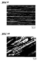
- Example 1a The procedure is as in Example 1a, with the difference that only one LC mixture (mixture 2, green, from Example la) is used. Electron micrographs (FIG. 7) show that, as in example 1a, only single-layer platelets with a layer thickness of approximately 6 ⁇ m are obtained.
- Example 1b The procedure is as in Example 1b with the difference that a layer package consisting of four layers is built up, the individual layers of which have a thickness of 4-5 ⁇ m, so that a total thickness 18 ⁇ m is obtained. Due to the increased overall thickness the four-layer package can be even easier detach from the carrier film as the two-layer package in the previous examples.
- electron microscope Images of the ground pigments show that, as in Examples 1a and 1b the platelets consist of only one layer.
- Example 1b The procedure is as in Example 1b with the difference that an LC mixture consisting of 64 g of hydroquinone bis- [4- (4-acryloylbutoxy) benzoate] (available from Broer, DJ; Mol, GN; Challa, G Makromol. Chem. 1991, 192, 59), 36 g methacrylic acid cholesterol ester (available from De Visser et al., J. Polym. Sci. A 1 (9), 1983 (1971)) 1.00 g photoinitiator Irgacure® 819 and 0.20 g of 2,6-di-tert-butyl-4- (dimethylaminomethylene) phenol (Ethanox® 703, Ethyl Corp., Baton Rouge, LA 70801) is used.
- an LC mixture consisting of 64 g of hydroquinone bis- [4- (4-acryloylbutoxy) benzoate] (available from Broer, DJ; Mol, GN; Challa, G Makromol. Chem. 1991,
- Example 1a This mixture is homogenized using a KPG stirrer at an oil bath temperature of 150 ° C. until a clear solution is obtained and then processed further in accordance with the process described in Example 1a. After the grinding process, green pigments are obtained. Electron micrographs show that these pigments, as in Example 1a, are exclusively single-layer platelets with a layer thickness of approximately 6 ⁇ m.
- Example 1b The procedure is as in Example 1b with the difference that an LC mixture consisting of 82.6 g of hydroquinone bis- [4- (4-acryloylbutoxy) benzoate] (available from Broer, DJ; Mol, GN; Challa , G. Makromol. Chem. 1991, 192, 59), 17.4 g 2,5-bis- [4- (acryloyloxy) benzoyl] isomannide (obtainable by the process described in Example 4 of patent application DE 199 17 067, an equivalent amount of isomannide is used as starting material instead of the isosorbide.
- hydroquinone bis- [4- (4-acryloylbutoxy) benzoate] available from Broer, DJ; Mol, GN; Challa , G. Makromol. Chem. 1991, 192, 59
- 17.4 g 2,5-bis- [4- (acryloyloxy) benzoyl] isomannide obtainable by the process described in Example 4 of patent application DE 199 17 06
- Example 2 Preparation of cholesteric platelets Structure (pigments) from a layer stack of 10 layers without using a cover film.
- Two cross-linkable, liquid-crystalline materials with chiral Phase are placed on a with the help of a doctor Glass plate 20 cm x 20 cm alternately applied in layers.
- the process takes place on a hot plate at a temperature of 110 ° C.
- Each layer is applied immediately after doctoring in a chamber filled with nitrogen with a UV hand lamp (uvhand 250, Fa. Hönle, Martinsried) networked.
- the shift package is replaced by the glass support at 20 ° C.
- the SEM image (Fig. 8) shows a layer package consisting of 10 layers with Layer thicknesses from 4 to 10 ⁇ m.
- the shift package becomes analog Example 1a crushed. Slides appear in the microscope green and red reflection color. SEM images of this ground Particles show that only particles that only consist of exist in one layer.
- Example 3a Preparation of cholesteric platelets Structure (pigments) from a layer package with 148 layers using a siliconized cover film
- a crosslinkable, liquid-crystalline material (LC material) with a chiral phase according to DE 199 17 067.3, example 10, is processed with the aid of an apparatus analogous to FIG. 5, but without elements 7 and 8.
- the material is applied to a rotating hard chrome roller (1) using a doctor blade (3). Doctor blade (3) and roller (1) are heated. The temperature is approx. 100 ° C.
- the distance between the knife edge and roller is set to 5 ⁇ m and a 5 ⁇ m thick LC film is knife-coated.
- a siliconized film analogous to Example 1a serves as the cover film for smoothing the material (5). It is cross-linked with a UV A lamp (4) (600 mJ / cm 2 in the UV A range).
- the distance between the doctor blades is increased by 5 ⁇ m, so that a further 5 ⁇ m layer can be applied to the existing LC layer.
- This coating process is carried out 148 times, so that a multi-layer layer package is produced with a uniform color.
- the roller circumference rotates at a speed of 10 cm / sec.
- the cylindrical layer package consisting of 148 layers with a thickness of 5 ⁇ m, is cut parallel to the roller axis and can be lifted off as a thick, free-standing layer package.
- the layer package is cut into narrow strips by a paper cutter and comminuted into pigments using an ultra-centrifugal mill type ZM 100 from Retsch, Haan, with a sieve ⁇ 80 ⁇ m.
- a visual assessment in the microscope shows platelet-shaped particles.
- SEM images (FIG. 9, section from the layer package and FIG. 10, bed of the ground material) show uniform layer thicknesses of 5 ⁇ m. Multi-layer particles could not be found.
- the spectrophotometric determination of the reflection band gives uniform values for the individual pigment particles. The determination is carried out with a Zeiss MPM 400 microscope spectrometer.
- Example 3b Preparation of cholesteric platelets Structure (pigments) from a layer package with 1508 layers using a siliconized cover film
- Example 3a The procedure is as in Example 3a, with the difference that the distance between the knife edge and the roller was set to 1 ⁇ m and a 1 ⁇ m thick LC film is knife-coated. Smoothing and Crosslinking takes place analogously to example 3a. After every turn the distance between the doctor blades is increased by 1 ⁇ m, so that another 1 ⁇ m layer is applied to the existing LC layer can be. This coating process is 1508 times executed so that a multi-layer package with uniform Color emerges. The roller circumference rotates at a speed of 12.5 cm / sec. The cylindrical layer package, consisting of 1508 layers with a thickness of 1 ⁇ m, is parallel to the Roll axis cut and can be as a thick, free-standing Shift package can be lifted off.
- the shift package is marked by a Paper cutter cut into narrow strips and with a Rotoplex granulator 20/12 (Hosokawa Alpine Augsburg) with sieve inserted ⁇ 0.8 mm to ⁇ 0.8 mm.
- the crushing to pigments was carried out in a jet milling system 100 AFG (Hosokawa Alpine Augsburg).
- the grain size histogram determined with a Mastersizer (Malvern Instruments Ltd, Malvern, UK), gives an average grain size of 25.6 ⁇ m.
- a visual one Assessment in the microscope shows platelet-shaped particles.
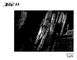
- An SEM picture (Fig. 11) on the bed of the regrind) shows uniform layer thicknesses of 1 ⁇ m.
- the spectrophotometric Determination of the reflection band results in the individual pigment particles uniform values. The determination is done with a Zeiss MPM 400 microscope spectrometer.
- Example 4 Production of platelets by continuous coating a hard chrome roller with 158 layers
- Example 3b of DE 42 40 743 corresponding US 5362315
- a shift package 158 layers with a thickness of 5 ⁇ m. It gets across Cut in the roller and press one against the roller Scraper lifted off in large clods without any residual coating remains on the roller.
- the 5 ⁇ m layers are crushed analogously to Example 1. Red pigments are obtained.
- a visual assessment in the microscope shows platelet-shaped Particles. SEM images of a bed of these milled Particles consist of single-layer pigments Layer thicknesses of 5 ⁇ m.
- Comparative Example 1 Production of cholesteric platelets Structure (pigments) with only one layer
- Example 1a The procedure is as in Example 1a, but from the green one LC mixture produced a single layer of approx. 6 ⁇ m. To the 6 ⁇ m thick LC single layer is removed by deflecting the carrier film over a breaking edge (Deflection radius 0.4 mm) broken. The resulting Raw clods can, however, unlike in the examples 1a-e, do not remove from the carrier film by suction alone.
- the procedure described in Example 1 can less than 5% of the LC film can be detached from the carrier film. Only through the use of powerful compressed air nozzles also with the single-layer process according to the prior art 90-95% achieved. Here are compressed air pressures of approx. 4 bar with a nozzle diameter of 1.5 mm and a nozzle spacing of about 2 cm required. A complete and residue-free detachment as with the described double layers is also not possible using compressed air.
- a liquid crystal film is produced from the green LC mixture described in Example 1a, but the layer thickness is only 4-5 ⁇ m.
- the reduction in the layer thickness means that once the cover film has been removed, the LC single layers can no longer be broken by deflecting the carrier film over a breaking edge with a deflection radius of 0.4 mm. Even with a significant reduction in the deflection radius to approximately 0.1 mm, at most isolated break points can be generated. In addition, the use of such a sharp breaking edge leads to significant damage to the carrier film, which can result in it tearing.
- the LC film which is only 4-5 ⁇ m thick and only incompletely broken over long stretches, cannot be removed from the carrier film even with the use of compressed air at further increased compressed air pressures of 7-8 bar with the compressed air nozzle described in comparative example 1a. No detachment of the LC film can be observed even in the area of existing break points.
- Example 6 Property profile of those produced in the multi-layer process pigments
- the liquid crystal pigments obtained in accordance with Examples 1b, 1c, 3 and 4 and Comparative Example 1a are mixed with a clear lacquer in a ratio of 1: 9 parts by weight.
- a conventional acrylate-melamine resin binder system from Herberts, Wuppertal, for automotive refinishing and a waterborne basecoat (Envirobase T 490 from PPG) are used as the clearcoat.
Description
Die Erfindung betrifft ein Verfahren zur Herstellung von Plättchen einer Dicke von 0,2 - 1000 µm und eines Durchmessers von 0,5 - 10 000 µm.The invention relates to a method for producing platelets a thickness of 0.2 - 1000 µm and a diameter of 0.5-10,000 µm.
Derartige Plättchen kommen in der Natur als Schuppen, Fischsilber oder Glimmerplättchen vor und werden als solche oder in oberflächenmodifizierter Form als Effektpigmente eingesetzt. Daneben sind künstliche Effektpigmente bekannt, die beispielsweise aus dünnen Plättchen cholesterischer Flüssigkristalle bestehen. Weiterhin finden solche Plättchen beispielsweise als rheologische Additive breite Anwendung.Such platelets come naturally as scales, fish silver or mica platelets before and are as such or in surface-modified form used as effect pigments. In addition, artificial effect pigments are known, for example consist of thin platelets of cholesteric liquid crystals. Such platelets are also found, for example, as rheological additives widely used.
In WO 93/08237, DE 196 18 563 A1, DE 196 18 566 A1 und DE 197 07 805 A1 ist die Herstellung von Interferenzpigmenten beschrieben, die aus hoch- und niedrigbrechenden, gegebenenfalls gefärbten oder vollkommen absorbierenden Schichten sowie Metallschichten bestehen. Die Herstellung dieser Interferenzpigmente erfolgt durch das Auftragen eines Materials oder mehrerer Materialien des Interferenzpigmentes auf ein Trägermaterial und anschließendes Ablösen der aus einem Material oder mehreren Materialien des Interferenzpigmentes bestehenden Schicht. Diese Schicht darf sich, auch wenn sie aus einzelnen Subschichten aufgebaut ist, beim Ablösen und den anschließenden Verarbeitungsschritten nicht in die Subschichten trennen, da hierdurch die charakteristischen Eigenschaften des Interferenzpigmentes verloren gehen. Eine Subschicht ist somit ein integraler Bestandteil eines gemäß Stand der Technik hergestellten Plättchens.In WO 93/08237, DE 196 18 563 A1, DE 196 18 566 A1 and DE 197 07 805 A1 describes the production of interference pigments, those of high and low refractive index, if necessary colored or completely absorbent layers as well as metal layers consist. The production of these interference pigments is done by applying one or more materials Materials of the interference pigment on a carrier material and subsequent detachment of one or more materials of the interference pigment existing layer. This Layer is allowed, even if it consists of individual sub-layers is built up during detachment and the subsequent processing steps do not separate into the sub-layers as this will result the characteristic properties of the interference pigment get lost. A sub-layer is therefore an integral part a plate manufactured according to the prior art.
Wenn die Materialien zur Herstellung der Schicht eine geringe Festigkeit haben, kann die Materialschicht von dem Trägermaterial nicht vollflächig abgezogen werden ohne zu reißen, sondern sie muß einem abrasiven Verfahren unterworfen werden. Speziell bei dünnen Schichten unter 10 µm ist dieser Verfahrensschritt kostenintensiv und mit Verschleißproblemen des Trägermaterials verbunden, insbesondere wenn es sich um eine als Trägermaterial allgemein übliche Terephthalatfolie (DE 196 18 566 A1, DE 197 07 805 A1) handelt. Um dieses Problem zu vermeiden, ist bekannt, Trennmittel auf das Trägermaterial aufzutragen, ehe das Material oder die Materialien, die das Interferenzpigment bilden, aufgetragen werden. Diese Vorgehensweise eignet sich hervorragend, wenn spröde Materialien das Interferenzpigment bilden. Es treten aber erhebliche Probleme auf, wenn es sich um Materialien mit hoher Bruchdehnung und geringer Reißfestigkeit handelt. Sie sind dann einerseits äußerst schwierig in Bruchstücke zu überführen, die durch Preßluft oder einen Absaugvorgang vom Trägermaterial entfernt werden können, andererseits sind sie nicht fest genug, um unbeschadet als Film vom Träger gelöst zu werden.If the materials used to make the layer are low Can have strength, the material layer of the carrier material not be pulled off over the whole area without tearing, but it must be subjected to an abrasive process. specially This process step is used for thin layers below 10 µm costly and with wear problems of the carrier material connected, especially if it is as a carrier material general terephthalate film (DE 196 18 566 A1, DE 197 07 805 A1). To avoid this problem, it is known Apply release agent to the carrier material before that Material or the materials that make up the interference pigment be applied. This is a great way to when brittle materials form the interference pigment. However, there are significant problems when it comes to Materials with high elongation at break and low tensile strength is. On the one hand, they are extremely difficult in To transfer fragments by compressed air or suction can be removed from the carrier material, on the other hand are they not firm enough to be seen as a film from Carrier to be released.
US 5,364,557 offenbart die Herstellung dünner cholesterischer
Plättchen durch Auftragen einer cholesterischen Schicht auf ein
Trägermaterial, z.B. auf eine Folie mittels eines Auftragswerkes,
bestehend aus einer Rakel oder einem Walzenauftragswerk.
Bei schmelzbaren Materialien erfolgt der Auftrag oberhalb der
Schmelz- oder Glastemperatur des Materials. Anschließend wird
das Material unterhalb der Schmelz- oder Glastemperatur vom
Substrat mit einem Luftstrahl, der gegebenenfalls ein abrasives
Pulver enthält, oder aber mit einem Schaber entfernt. Als spezielle
Ausführungsform wird die Übertragung auf ein weiteres
Trägermaterial beschrieben. Weiterhin wird die Erzeugung von
Schichten, die aus Stoffen mit unterschiedlichen Eigenschaften
bestehen, offenbart. So werden Doppelschichten, bestehend aus
links- und rechtshelikalem Material, beschrieben, die beim Zerkleinerungsvorgang
Plättchen liefern, die sowohl aus einer
links- und als auch aus einer rechtshelikalen Schicht bestehen
und beim Zerkleinerungsvorgang nicht in weitere Schichten zerfallen.
Alle in US 5,364,557 offenbarten Verfahrensweisen führen zu einer
einzigen ggf. aus Subschichten aufgebauten Schicht, aus
welcher durch Brechen Plättchen gewonnen werden, welche die Dicke
der dem Mahlvorgang unterworfenen Schicht besitzen. No. 5,364,557 discloses the production of thin cholesteric platelets by applying a cholesteric layer on a carrier material, for example on a film, by means of an applicator consisting of a doctor blade or a roller applicator. For meltable materials, the application takes place above the melting or glass temperature of the material. The material is then removed from the substrate below the melting or glass temperature with an air jet, which may contain an abrasive powder, or with a scraper. The transfer to another carrier material is described as a special embodiment. Furthermore, the creation of layers consisting of substances with different properties is disclosed. For example, double layers consisting of left and right helical material are described which deliver platelets during the shredding process, which consist of a left and right helical layer and do not disintegrate into further layers during the shredding process.
All of the procedures disclosed in US Pat. No. 5,364,557 lead to a single layer, optionally made up of sublayers, from which plates are obtained by breaking, which have the thickness of the layer subjected to the milling process.
Auch DE 42 40 743 (entspricht US 5,362,315) offenbart die Herstellung vernetzter cholesterischer Plättchen über Einfachschichten.DE 42 40 743 (corresponds to US 5,362,315) also discloses the production cross-linked cholesteric platelets over single layers.
Gemäß EP 07 93 693 erfolgt die Herstellung vernetzter cholesterischer Plättchen durch Bedrucken eines Trägers mit cholesterischem Material, durch Vernetzen und durch anschließendes Entfernen des aufgedruckten, vernetzten Materials. Auch hier geht man von einer einzelnen Schicht aus, die dem letztendlich erhaltenen cholesterischen Plättchen entspricht.According to EP 07 93 693, crosslinked cholesteric is produced Platelets by printing on a carrier with cholesteric Material, by crosslinking and then removing of the printed, cross-linked material. Here too one from a single layer, the one ultimately obtained corresponds to cholesteric platelets.
DE 197 57 699 offenbart ein Verfahren zur Herstellung plättchenförmiger, cholesterischer Mehrschichtinterferenzpigmente, gekennzeichnet durch die Schichtfolgen A1-B-A2, wobei A1 und A2 unterschiedlich sein können, jedoch mindestens eine cholesterische Schicht umfassen und B für eine trennende Zwischenschicht steht, die das die Schichten A1 und A2 transmittierende Licht teilweise oder vollständig absorbiert. Die offenbarten Mehrschichtpigmente haben einen Durchmesser von 5 bis 500 µm. Die Schichtdicken der einzelnen cholesterischen Schichten A1 oder A2 betragen 0,5 bis 20 µm, während die Schichtdicke jeder einzelnen Schicht B 0,2 bis 5 µm beträgt.DE 197 57 699 discloses a process for producing platelet-shaped, cholesteric multilayer interference pigments, characterized by the Layer sequences A1-B-A2, whereby A1 and A2 can be different, however comprise at least one cholesteric layer and B for a separating layer Intermediate layer stands, the light that transmits the layers A1 and A2 partially or completely absorbed. The multi-layer pigments disclosed have one Diameters from 5 to 500 µm. The layer thickness of each cholesteric Layers A1 or A2 are 0.5 to 20 µm, while the layer thickness of each single layer B is 0.2 to 5 microns.
Alle genannten Verfahren sind abhängig von der Leichtigkeit, mit welcher der vernetzte oder unterhalb der Glastemperatur befindliche Film vom eingesetzten Substrat abgelöst werden kann. Je fester der cholesterische Film auf dem Trägermaterial haftet, desto größerer mechanischer Beanspruchung muß das Trägermaterial beim Ablösen der cholesterischen Schicht ausgesetzt werden. Dies führt zu hohem Verschleiß des Trägermaterials und damit zu erhöhten Produktionskosten für die cholesterischen Filme. Besonders drastisch treten Probleme auf, wenn Schichten unter 10 µm Dicke, bestehend aus einem nicht spröden Material, abgelöst werden müssen.All of the above methods depend on the ease, with which the networked or below the glass temperature Film can be detached from the substrate used. The more firmly the cholesteric film adheres to the carrier material, the greater the mechanical stress on the carrier material exposed when the cholesteric layer is detached become. This leads to high wear of the carrier material and thereby increasing production costs for the cholesteric Movies. Problems occur particularly drastically when layers less than 10 µm thick, consisting of a non-brittle material, have to be replaced.
Aufgabe der Erfindung ist es daher, ein Verfahren bereitzustellen, das es ermöglicht, auch aus Materialien mit hoher Reißdehnung und geringer Reißfestigkeit ohne die genannten Probleme Plättchen einer Dicke von 0,1-1000 µm und eines Durchmessers von 0,5 -10 000 µm herzustellen.The object of the invention is therefore to provide a method that makes it possible even from materials with high elongation at break and low tensile strength without the problems mentioned Small plates with a thickness of 0.1-1000 µm and a diameter of 0.5-10 000 µm.
Diese Aufgabe wird gelöst durch ein Verfahren, bei dem ein zu Plättchen zu verarbeitendes Material in fließfähigem oder gasförmigem Zustand auf einen Träger aufgetragen, verfestigt, von dem Träger entfernt und einem Brech- oder Mahlprozeß unterzogen wird, dadurch gekennzeichnet, daß das Material auf den Träger derart übereinander aufgetragen wird, daß nach dem Auftragen ein Schichtpaket vorliegt, welches im Querschnitt senkrecht zu seiner Oberfläche Einzelschichten einer Dicke zwischen 0,2 - 1000 µm enthält, wobei die Festigkeit des Schichtpakets parallel zum Schichtverlauf größer ist, als senkrecht zum Schichtverlauf, und dieses Schichtpaket nach Ablösen von dem Träger derart behandelt wird, daß das Material in Einzelschichten zerfällt und die Einzelschichten auf eine Teilchengröße von 0,5 - 10000 µm zerkleinert werden.This problem is solved by a method in which a Material to be processed in flowable or gaseous form Condition applied to a carrier, solidified, from removed from the carrier and subjected to a crushing or grinding process is characterized in that the material on the carrier is applied one above the other in such a way that after application there is a layer package which is perpendicular to the cross section individual layers with a thickness between 0.2 - Contains 1000 µm, the strength of the layer package parallel to the course of the layer is greater than perpendicular to the course of the layer, and this layer package after detachment from the Carrier is treated so that the material in individual layers disintegrates and the individual layers to a particle size of 0.5 - 10000 µm can be crushed.
Ein Schichtpaket wird vorzugsweise dadurch erhalten, daß unverfestigtes, zu Plättchen zu verarbeitendes Material, zunächst in üblicher Weise auf einen Träger aufgebracht und verfestigt wird und anschließend auf dieses verfestigte Material wiederum unverfestigtes zu Plättchen zu verarbeitendes Material aufgebracht und verfestigt wird, ohne daß es dabei zu einem Verschweißen oder Blocken der einzelnen Materialschichten miteinander kommt. Hierfür geeignete Prozeßschritte sind beispielsweise das Auftragen und Polymerisieren oder Vernetzen polymerisierbarer oder vernetzbarer Materialien auf eine bereits polymerisierte oder vernetzte Schicht oder das Aufbringen einer Schmelze auf erstarrtes, kaltes Material.A layer package is preferably obtained in that unconsolidated, material to be processed into platelets, first in is usually applied to a carrier and solidified and then unconsolidated onto this solidified material material to be processed into platelets and is solidified without welding or blocking the individual layers of material with one another comes. Process steps suitable for this are, for example applying and polymerizing or crosslinking polymerizable or crosslinkable materials onto an already polymerized one or cross-linked layer or applying one Melt on solidified, cold material.
Gegebenenfalls wird das Schichtpaket unter Verwendung eines Trennmittels erzeugt. Dabei wird auf eine verfestigte Materialschicht vor dem Auftrag einer unverfestigten Materialschicht ein Trennmittel aufgetragen. Der Auftrag des Trennmittels kann zwischen jeder Einzelschicht oder jeweils nach einer bestimmten Anzahl von Schichten erfolgen. Zur Herstellung mehrschichtiger Plättchen wird das Trennmittel jeweils nach der Anzahl von Schichten (Subschichten), die nach dem Zerkleinern ein mehrschichtiges Plättchen bilden, aufgetragen. Im Sinne der vorliegenden Erfindung handelt es sich auch bei einem solchen mehrschichtigen flächenhaften Gebilde, welches beim Ablösen vom Träger und beim Mahlprozess nicht in Einzelschichten (Subschichten) zerfällt, um eine Einzelschicht. Eine Einzelschicht im Sinne der vorliegenden Erfindung kann daher durchaus, wie auch aus dem Stand der Technik bekannt, aus mehreren Subschichten, die miteinander untrennbar verbunden sind, bestehen.If necessary, the layer package is used using a Release agent generated. This is done on a solidified material layer before applying an unconsolidated layer of material a release agent applied. The release agent can be applied between each individual layer or after a certain one Number of layers are done. To produce multilayer The release agent becomes platelet according to the number of Layers (sub-layers), which after crushing a multilayer Form platelets, applied. In the sense of the present Invention is also such a multilayer flat structure, which when detached from Carrier and in the grinding process not in individual layers (sub-layers) decays to a single layer. A single layer in the sense of the present invention can therefore quite how also known from the prior art, from several sub-layers, that are inseparable from each other.
Das Schichtpaket wird vorzugsweise durch zwei- oder mehrmaliges Auftragen und Verfestigen des zu verarbeitenden Materials, welches eine Einzelschicht bildet, hergestellt. Bevorzugt besteht ein Schichtpaket aus mehr als 6 Einzelschichten, besonders bevorzugt aus mehr als 10 Einzelschichten.The layer package is preferably made two or more times Applying and solidifying the material to be processed, which forms a single layer. Preferably there is a layer package of more than 6 individual layers, particularly preferred from more than 10 individual layers.
Nach dem Aufbau des aus mindestens zwei Einzelschichten bestehenden Pakets wird dieses vom Träger entfernt, wobei eine erste Schicht des Materials auf dem Träger verbleiben kann, und dann einem Brech- und/oder Mahlwerk zugeführt.After building up the consisting of at least two individual layers Package is removed from the carrier, being a first Layer of material can remain on the carrier, and then fed to a crushing and / or grinder.
Als Träger, auf den die erste Schicht des zu Plättchen zu verarbeitenden Materials aufgetragen wird, eignet sich jedes Material, das bei der Verfestigungstemperatur des aufzutragenden Materials fest ist. Dies sind beispielsweise Metalle wie Eisen, Stahl, legierte Stähle, Messing, Chrom, Kupfer oder Kunststoffe wie gesättigte Polyester (PET), Polyethylen (PE), Polypropylen (PP), Polystyrol (PS), vernetzte ungesättigte Polyester, Polytetrafluorethylen (Teflon), Polyimide und Polyamide sowie anorganische oxidische und nichtoxidische Werkstoffe wie Porzellan, Siliciumcarbid, Wolframcarbid, Borcarbid, Siliciumnitrid, Mischkeramiken, Granit und Glas oder Kombinationen dieser Werkstoffe in Form beschichteter Werkstoffe oder aus ihnen hergestellte Verbundwerkstoffe.As a carrier on which the first layer of the platelet to be processed Material is applied, any material is suitable that at the solidification temperature of the to be applied Material is solid. These are, for example, metals like iron, Steel, alloyed steels, brass, chrome, copper or plastics such as saturated polyester (PET), polyethylene (PE), polypropylene (PP), polystyrene (PS), cross-linked unsaturated polyester, polytetrafluoroethylene (Teflon), polyimides and polyamides as well as inorganic oxidic and non-oxidic materials such as porcelain, Silicon carbide, tungsten carbide, boron carbide, silicon nitride, Mixed ceramics, granite and glass or combinations of these materials in the form of coated materials or made from them Composites.
Als Träger können platten-, zylinder-, röhren- oder bandförmige Körper gewählt werden. Ihre Oberflächen können rauh, geschliffen, poliert, oberflächenvergütet und / oder mit einer Trennschicht versehen sein. Vorzugsweise handelt es sich um zylinderförmige Körper oder Körper, die gegebenenfalls konisch oder parabolisch ausgebildet sind.Plate, cylindrical, tubular or band-shaped can be used as carriers Body can be chosen. Your surfaces can be rough, ground, polished, surface coated and / or with a separating layer be provided. It is preferably cylindrical Body or body that may be conical or are parabolic.
Materialien, die im erfindungsgemäßen Verfahren eingesetzt werden können, sind vernetzbare Materialien oder Stoffe, die aus der flüssigen in eine feste Phase übergeführt werden können, sei es durch Erstarren einer Schmelze, sei es durch Verdampfen eines Lösungsmittels, sei es durch Kristallisation oder eine Vernetzungsreaktion. Materials that are used in the method according to the invention can be cross-linkable materials or substances made from the liquid phase can be converted into a solid phase, be it by solidifying a melt or by evaporation of a solvent, be it by crystallization or a Crosslinking reaction.
Beispiele für solche Materialien sind gesättigte und ungesättigte Polyester, Epoxide, Vinylester, Vinyläther, Polyurethane, Silane, Siloxane, Silanolate, Wasserglas, Kieselsäureester, flüssigkristalline, polymerisierbare oder vernetzbare aromatische, cycloaliphatische oder heterocyclische Verbindungen wie Epoxide mit den Amino-, Hydroxy- oder Anhydridkomponenten, Vinylester, Vinyläther, Isocyanate als solche oder mit den entsprechenden HO-Komponenten in monomerer oder oligomerer Form, Silane oder Siloxane. Weiterhin sind verfilmende Dispersionen und Harzlösungen zu nennen, die vernetzbare oder nichtvernetzbare Harze enthalten.Examples of such materials are saturated and unsaturated Polyester, epoxies, vinyl esters, vinyl ethers, polyurethanes, Silanes, siloxanes, silanolates, water glass, silicic acid esters, liquid crystalline, polymerizable or crosslinkable aromatic, cycloaliphatic or heterocyclic compounds such as Epoxides with the amino, hydroxy or anhydride components, vinyl esters, Vinyl ether, isocyanates as such or with the corresponding HO components in monomeric or oligomeric form, Silanes or siloxanes. There are also filming dispersions and to name resin solutions that are crosslinkable or non-crosslinkable Resins included.
Vorzugsweise handelt es sich um polymerisierbare, vernetzbare, flüssigkristalline, nematische, smektische, chiral nematische und chiral smektische Materialien. Vorzugsweise haben die Materialien eine cholesterische Phase.They are preferably polymerizable, crosslinkable, liquid crystalline, nematic, smectic, chiral nematic and chiral smectic materials. Preferably the materials a cholesteric phase.
Die Materialien können rein oder in Kombination mit anderen Stoffen wie beispielsweise Hilfsstoffen oder Wirkstoffen eingesetzt werden. Hilfsstoffe sind z.B. Füllstoffe, Farbstoffe, Pigmente oder Initiatoren für radikalische oder ionische Polymerisationen, für Polyadditionen, Kondensationen oder für Hydrosilylierungen.The materials can be pure or in combination with others Substances such as excipients or active ingredients are used become. Auxiliaries are e.g. Fillers, dyes, Pigments or initiators for radical or ionic polymerizations, for polyadditions, condensations or for hydrosilylations.
Die Wirkstoffe können gelöst oder als zweite Phase im Material vorliegen. Es handelt sich z.B. um Pharmazeutika, Herbizide oder Pestizide.The active ingredients can be dissolved or as a second phase in the material available. It is e.g. pharmaceuticals, herbicides or pesticides.
Die Materialien können auch in dispergierter Form Flüssigkeiten enthalten, z.B. niedermolekulare flüssigkristalline Substanzen, die in üblicher Weise z.B. durch Anlegen elektrischer Felder in den Plättchen geschaltet werden können.The materials can also be in dispersed liquids included, e.g. low molecular weight liquid crystalline substances, which in the usual way e.g. by applying electrical fields in the tiles can be switched.
Die zweite Phase kann in der Matrix des einzusetzenden Materials bereits vor Durchführung des erfindungsgemäßen Verfahrens vorliegen oder sie kann während des erfindungsgemäßen Verfahrens durch Phasenseparation entstehen. The second phase can be in the matrix of the material to be used even before the method according to the invention is carried out or it can be present during the process according to the invention arise through phase separation.
Darüber hinaus können verfilmende Dispersionen, Suspensionen, Pulverlacke oder vergleichbare Systeme sowie durch Sputtern oder Verdampfen aufbringbare Stoffe als Ausgangsmaterialien im erfindungsgemäßen Verfahren eingesetzt werden.In addition, filming dispersions, suspensions, Powder coatings or comparable systems as well as by sputtering or evaporable materials as starting materials in the inventive methods are used.
Beispielsweise handelt es sich dabei um polymerisierbare, polyaddierbare, hydrosilylierbare, polykondensierbare, vernetzbare Stoffe, schmelzbare Harze, Thermoplaste, durch Verdampfen von Lösemitteln in Filme überführbare Lösungen, Suspensionen und durch Polymerisation in Zweiphasensysteme überführbare Mischungen, die gegebenenfalls Hilfsstoffe wie Photoinitiatoren, Peroxide, UV-Absorber, Farbstoffe oder Pigmente enthalten.For example, these are polymerizable, polyaddable, hydrosilylatable, polycondensable, crosslinkable Fabrics, meltable resins, thermoplastics, by evaporation of Solvents, suspensions and films which can be converted into films mixtures which can be converted into two-phase systems by polymerization, any auxiliary substances such as photoinitiators, peroxides, Contain UV absorbers, dyes or pigments.
Der Aufbau des Schichtpakets kann mit einem oder mit mehreren der genannten Materialien erfolgen. Voraussetzung für das erfolgreiche Durchführen des erfindungsgemäßen Verfahrens ist, daß die Festigkeit des Schichtpakets parallel zum Schichtverlauf größer ist als senkrecht zu den Schichten.The layer package can be constructed with one or more of the materials mentioned. Prerequisite for successful Is to carry out the method according to the invention, that the strength of the layer package parallel to the course of the layer is larger than perpendicular to the layers.
Der Aufbau eines Schichtpakets aus den genannten Materialien kann ohne oder mit einem Trennmittel durchgeführt werden. Als Trennmittel können Verbindungen, ausgewählt aus der Gruppe der Silicone, außerdem Tenside, Polyether, Polyvinylalkohol (PVA), hochdisperse Kieselsäure (HDK), Talkum, Teflonpulver, Graphit, Molybdänsulfid, Glimmerpulver und Metallplättchen (z.B. Al oder Messing) eingesetzt werden.The construction of a layer package from the materials mentioned can be carried out without or with a release agent. As Release agents can be selected from the group of compounds Silicones, also surfactants, polyethers, polyvinyl alcohol (PVA), finely divided silica (HDK), talc, Teflon powder, graphite, Molybdenum sulfide, mica powder and metal flakes (e.g. Al or Brass) can be used.
Die Trenneigenschaften des Trennmittels können unmittelbar nach der Entfernung des Schichtpakets vom Träger wirksam sein oder aber beispielsweise bei einem Schichtpaket aus anorganischem Material in einem nachfolgenden Kalzinierungsschritt wirksam werden. Dies kann beispielsweise im Fall eines organische Trennschichten enthaltenden Schichtpakets durch Kalzinieren in oxidierender Atmosphäre über 150°C oder durch Aufblähen einer beispielsweise Wasser, CO2 oder N2 abspaltenden Trennschicht geschehen. The release properties of the release agent can be effective immediately after the layer package has been removed from the support or, for example, can be effective in a subsequent calcination step in the case of a layer package made of inorganic material. In the case of a layer package containing organic separating layers, this can be done, for example, by calcining in an oxidizing atmosphere above 150 ° C. or by blowing up a separating layer which, for example, eliminates water, CO 2 or N 2 .
Der gleiche Effekt wie durch das Aufbringen eines Trennmittels zwischen den einzelnen Schichten läßt sich mit vernetzbaren Materialien dadurch erzeugen, daß die Schichten aus vernetzbaren Materialien, deren Trennung zunächst unerwünscht ist, nur schwach vernetzt werden, die Schicht, an welcher die Trennung erfolgen soll, jedoch stark vernetzt wird.The same effect as applying a release agent crosslinkable materials can be used between the individual layers by making the layers of cross-linkable Materials whose separation is initially undesirable, only weakly networked, the layer at which the separation should take place, but is strongly networked.
Der Auftrag der Materialien kann durch verschiedene Verfahren erfolgen. Beispielhaft seien Auftragsmöglichkeiten durch Walzen, Rakeln, Sprühen in flüssiger Form mit oder ohne Lösungsmittel oder in Form von Pulvern gemäß den bekannten Pulvertechnologien genannt sowie Aufdampfen und Sputtern. Der Auftrag kann mit einem oder mehreren Auftragswerken geschehen, wobei das Material bzw. die Materialien jeweils zwischen den Auftragswerken in die gewünschte feste Form übergeführt werden muß/müssen. Dies geschieht je nach Material in bekannter Art und Weise durch Trocknen, Polymerisieren, Vernetzen oder Kühlen. Die Schichtpakete können gegebenenfalls unter Verwendung von Glättungselementen erzeugt werden.The materials can be applied by various methods respectively. Examples are application options by rolling, Squeegees, spraying in liquid form with or without solvent or in the form of powders according to known powder technologies called as well as evaporation and sputtering. The order can be done with one or more commissioned works, whereby the material or materials between the commissioned works be converted into the desired solid form must / must. Depending on the material, this is done in a known manner and by drying, polymerizing, crosslinking or cooling. The layer packs can optionally be used generated by smoothing elements.
Wenn es sich bei den zu Plättchen zu verarbeitenden Materialien um flüssigkristalline Materialien handelt, so erfolgt der Schichtaufbau vorzugsweise in Gegenwart von Flüssigkristalle orientierenden Hilfsstoffen oder elektrischen oder magnetischen Feldern. Entsprechende Verfahren sind aus dem Stand der Technik bekannt. Bei solchen Materialien erfolgt der Aufbau des Schichtpakets vorzugsweise ohne den Einsatz eines Trenmittels.If it is the materials to be processed into platelets are liquid-crystalline materials, so the Layer structure preferably in the presence of liquid crystals orienting auxiliaries or electrical or magnetic Fields. Corresponding methods are from the prior art known. With such materials, the structure of the Layer packages preferably without the use of a release agent.
Nach Aufbau einer Schichtabfolge im gewünschten Umfang wird das Schichtpaket vom Träger gelöst und einem Zerkleinerungsprozeß unterworfen.After building up a shift sequence to the desired extent, this will be Layer package released from the carrier and a comminution process subjected.
Das Ablösen des Schichtpakets kann dabei auch durch Abtragen von Schichten auf der dem Auftragswerk gegenüberliegenden Seite erfolgen. Das Abtragen erfolgt vorzugsweise kontinuierlich.The layer package can also be removed by removal of layers on the side opposite the application respectively. The removal is preferably carried out continuously.
Der Zerkleinerungsprozeß kann beispielsweise in einem Kollergang, einer Kugelmühle, einer Stiftmühle oder einer Luftstrahlmühle durchgeführt und das Material anschließend klassiert werden.The crushing process can take place, for example, in a pan mill, a ball mill, a pin mill or an air jet mill and the material is then classified.
Das erfindungsgemäße Verfahren kann auch dergestalt durchgeführt werden, daß Materialien mit unterschiedlichen Eigenschaften unmittelbar nacheinander aufeinander aufgebracht werden, mit der Maßgabe, daß diese miteinander fest verbundenen Doppeloder Mehrfachschichten die Einzelschichten des entstehenden Schichtpakets darstellen, die beim Mahlprozeß die gewünschten Plättchen mit der gewünschten Schichtabfolge liefern.The method according to the invention can also be carried out in this way that materials with different properties applied one after the other, with the proviso that these double or Multiple layers the individual layers of the resulting Layer packets, which are the desired ones during the grinding process Deliver tiles with the desired layer sequence.
Mittels des erfindungsgemäßen Verfahrens lassen sich daher auch
Plättchen mit Schichtaufbau realisieren. So lassen sich verschiedene
Materialkombinationen z. B. AB, ABA, ABC usw. (A =
Material 1, B = Material 2, C = Material 3) erzeugen. Beispielsweise
können Doppel-, Dreifach- oder n-fach Schichten aus
cholesterischen Flüssigkristallen mit jeweils unterschiedlichen
Reflexionswellenlängen oder unterschiedlicher Helizität erhalten
werden. Auch Kombinationen von cholesterischen Schichten
mit planar orientierten nematischen Schichten, die linear polarisiertes
Licht reflektieren, oder Kombinationen von cholesterischen
Schichten mit homeotrop orientierten nematischen oder
smektischen Schichten sind möglich.The method according to the invention can therefore also be used
Realize tiles with layer structure. So different ones can be
Material combinations e.g. B. AB, ABA, ABC etc. (A =
Im Folgenden werden beispielhaft weitere Eigenschaftskombinationen in den Plättchen genannt, die durch das erfindungsgemäße Verfahren realisiert werden können: Hohe / niedrige Dielektrizitätskonstante; hohes / niedriges el. Dipolmoment; hohe / niedrige el. oder optische Polarisierbarkeit; hoher / niedriger Brechungsindex; doppelbrechend / isotrop; transparent / streuend; transparent / absorbierend; streuend / absorbierend; hydrophil / hydrophob; lipophil / lipophob; el. leitend / nicht leitend; hoher / niedriger el. Widerstand; ionisch / neutral; anionisch / kationisch; magnetisch / nicht magnetisch; magnetisierbar / nicht magnetisierbar; quellbar / nicht quellbar; nur in org. Lösungsmitteln quellbar / nur in Wasser quellbar. The following are examples of further property combinations called in the platelets by the inventive Processes can be realized: high / low dielectric constant; high / low el. dipole moment; height / low electrical or optical polarizability; higher / lower Refractive index; birefringent / isotropic; transparent / scattering; transparent / absorbent; scattering / absorbing; hydrophilic / hydrophobic; lipophilic / lipophobic; el. conductive / not conductive; high / low electrical resistance; ionic / neutral; anionic / cationic; magnetic / non-magnetic; magnetizable / not magnetizable; swellable / not swellable; just in org. Solvent swellable / swellable only in water.
Die erfindungsgemäß hergestellten Plättchen können weiteren Prozeßschritten wie beispielsweise dem Beschichten mit Metallen und Metalloxiden zugeführt werden.The platelets produced according to the invention can be further Process steps such as coating with metals and metal oxides are supplied.
Eine Variante des erfindungsgemäßen Verfahrens läßt sich beispielsweise durch Modifizierung des in DE 42 40 743 A1 beschriebenen Verfahrens verwirklichen. Gemäß DE 42 40 743 A1 wird die Vernetzungsreaktion des zu Plättchen zu verarbeitenden Materials zwischen zwei Folien, einer Träger- und Deckfolie ausgeführt. Dieses Verfahren wird dadurch zum erfindungsgemäßen Verfahren modifiziert, daß die erste, zwischen Träger- und Deckfolie befindliche Schicht von der Deckfolie befreit wird und die Schicht mit der Trägerfolie einem oder mehreren weiteren Beschichtungsschritten analog der Beschichtung des Trägers unterworfen wird. Ein auf diese Weise hergestelltes Schichtpaket in Form eines Schichtstapels läßt sich von dem Träger erheblich besser ablösen als eine Einfachschicht.In dieser erfindungsgemäßen Verfahrensvariante wird die Trägerfolie ohne Trennmittel oder Trennschicht eingesetzt.A variant of the method according to the invention can be, for example by modifying that described in DE 42 40 743 A1 Realize procedure. According to DE 42 40 743 A1 becomes the crosslinking reaction of the to be processed into platelets Material between two films, a carrier and cover film executed. This process thus becomes the invention Modified procedure that the first, between carrier and Covering film is freed of the cover film and the layer with the carrier film one or more others Coating steps analogous to the coating of the carrier is subjected. A layer package produced in this way in the form of a layer stack can be considerably from the carrier peel off better than a single layer. In this invention Process variant is the carrier film without Release agent or release layer used.
Diese Variante des erfindungsgemäßen Verfahrens arbeitet sowohl bezüglich des Materialauftrags als auch bezüglich der Gewinnung des Schichtpakets diskontinuierlich. Sie kann jedoch durch Einsatz von Endlosträgern und mehrfach hintereinandergeschalten Auftrags- und Härtungseinheiten, die zum Aufbau einer Mehrfachschicht führen, gefolgt von einer Ablöseeinheit, kontinuierlich gestaltet werden.This variant of the method according to the invention works both with regard to the material application as well as in terms of extraction of the shift package discontinuously. However, you can by using of endless carriers and connected in series several times Application and hardening units that build up a multi-layer lead, followed by a detachment unit, continuously be designed.
In Fig. 1 bis 3 sind beispielhaft weitere Arten des Materialauftrags für den Aufbau eines Schichtpakets, aus welchem Plättchen diskontinuierlich oder kontinuierlich gewonnen werden können, schematisch dargestellt, wobei der Materialauftrag kontinuierlich oder diskontinuierlich erfolgt. Die Pfeile geben die Richtung des Auftrags an.1 to 3 are examples of further types of material application for building a layer package, from which platelet can be obtained discontinuously or continuously, shown schematically, the material application continuously or discontinuously. The arrows indicate that Direction of the order.
Der Auftrag des Materials gemäß Fig. 1 erfolgt beispielsweise auf der Außenseite eines rotierenden Zylinders als Träger mittels eines Auftragswerks. Schematisch ist dieser Vorgang in Fig. 4 a dargestellt. Analog ist der Auftrag auf die Innenseite eines Zylinders als Träger möglich. Ist die Umlaufzeit des unverfestigten Materials auf dem Zylinder größer als die zur Verfestigung benötigte Zeit, kann die Verfestigung kontinuierlich erfolgen und es entsteht ein rollenförmiges Schichtpaket. Ist die Umlaufzeit des unverfestigten Materials auf dem Zylinder geringer als die Verfestigungzeit, so erfolgt der Materialauftrag dikontinuierlich, nach Auftrag eines Zylinderumfangs unverfestigten Materials erfolgt die Verfestigung, nach der Verfestigung erfolgt der nächste Auftrag eines Zylinderumfangs unverfestigten Materials usw.. Es entsteht statt eines rollenförmigen Schichtpackets ein ringförmig aufgebautes Schichtpaket wie in Fig. 4b dargestellt. Der Auftrag des Materials auf der Innenseite eines Zylinders kann in der schon beschriebenen Weise erfolgen, er kann aber auch durch einen Spritzvorgang, gefolgt von Nivellierung des Materials durch die Zentrifugalbeschleunigung erfolgen.The application of the material according to FIG. 1 takes place, for example on the outside of a rotating cylinder as a carrier a commissioned work. This process is schematic in Fig. 4 a shown. The order on the inside is analogous a cylinder as a carrier possible. Is the orbital period of the unsolidified Material on the cylinder larger than that for solidification time required, the solidification can be continuous take place and a roll-shaped layer package is created. is the round trip time of the unconsolidated material on the cylinder less than the solidification time, the material is applied discontinuous, after application of a cylinder circumference unconsolidated Solidification takes place after the solidification the next order of a cylinder circumference is unconsolidated Materials etc. It is created instead of a roll-shaped one Layer packets are a ring-shaped layer packet as shown in Fig. 4b. The order of the material on the Inside of a cylinder can in the manner already described done, but it can also be followed by a spraying process of leveling the material by centrifugal acceleration respectively.
Der Aufbau einer Apparatur, welche zur Herstellung eines Schichtpakets in Form einer Rolle auf einem Zylinder aus mittels UV- Strahlung vernetzbaren Materials geeignet ist, ist in Fig. 5 dargestellt.The construction of an apparatus which is used to manufacture a Layer packages in the form of a roll on a cylinder by means of UV radiation of crosslinkable material is suitable in Fig. 5 shown.
Das Material wird aus einem Materialreservoir (2) mit einem Walzenauftragswerk (3) auf einen rotierenden Zylinder (1) aufgetragen, mit einer zur Polymerisation erforderlichen UV-Strahlung ausreichend durchlässigen Folie (5) geglättet und mittels UV-Strahlung vernetzt(4). Nach der Vernetzung kann eine Trennhilfe aufgetragen werden oder bei flüssigkristallinen Materialien eine Orientierungshilfe(7), welche in einem nachgeschalteten Arbeitsgang, beispielsweise durch Reiben(8), vorbehandelt wird. Als Orientierungshilfe (7) können beispielsweise auch photochemisch erzeugte Orientierungschichten verwendet werden.The material is made from a material reservoir (2) with a Roller applicator (3) applied to a rotating cylinder (1), with UV radiation required for the polymerization sufficiently permeable film (5) smoothed and cross-linked by UV radiation (4). After networking, one can Separation aid can be applied or for liquid crystalline materials an orientation aid (7), which in a downstream Operation, for example by rubbing (8), pretreated becomes. As a guide (7), for example also used photochemically generated orientation layers become.
Die Folie (5) kann gegebenenfalls oberflächenbehandelt sein, sie kann beispielsweise eine Siliconschicht tragen. Die Folie (5) hat neben ihrer Glättungsfunktion die Aufgabe, Luftsauerstoff, der die Vernetzung negativ beeinflußt, von der zu vernetzenden Oberfläche fernzuhalten. Diese Aufgabe entfällt, wenn die Apparatur unter Inertgas betrieben wird.The film (5) can optionally be surface-treated, for example, it can carry a silicone layer. The foil (5) In addition to its smoothing function, it has the task of which negatively influences the networking, of the one to be networked Keep the surface away. This task does not apply if the apparatus is operated under inert gas.
Ist die gewünschte Schichtenanzahl erreicht, wird das spiralförmig aufgebaute Schichtpaket (6) vom zylindrischen Kern (1) entfernt und einem Mahlwerkzeug zugeführt.When the desired number of layers is reached, it becomes spiral assembled layer package (6) from the cylindrical core (1) removed and fed to a grinding tool.
Eine weitere Variante des Verfahrens ist in Fig. 6 dargestellt. Ein flexibler Träger (9) wird nach Verfahren, wie sie aus dem Stand der Technik bekannt sind, z.B. aus einem Materialreservoir (10) mit einem Auftragswerk (11) mit einem durch Strahlung (UV, Elektronenstrahl) vernetzbaren Material beschichtet. Der beschichtete flexible Träger (12) überträgt das Material kontinuierlich auf einen rotierenden, zylindrischen Kern (1). Dort wird das Material UV-vernetzt oder mittels Elektronenstrahl gehärtet (4). Dieses kontinuierliche Beschichtungsverfahren führt zu einem Schichtpaket in Form einer Rolle. Der von der Beschichtung befreite Träger (9) kann entweder als Endlosband ständig sofort wiederverwendet werden oder, wie in Fig. 6 dargestellt, von Rolle zu Rolle durchlaufen.Another variant of the method is shown in FIG. 6. A flexible carrier (9) is made according to the method from the Are known in the art, e.g. from a material reservoir (10) with an order work (11) with a radiation (UV, electron beam) crosslinkable material coated. The coated flexible carrier (12) transfers the material continuously on a rotating, cylindrical core (1). There the material is UV crosslinked or hardened using an electron beam (4). This continuous coating process results to a shift package in the form of a roll. The one from the coating exempted carrier (9) can either be an endless belt can be reused immediately immediately or, as shown in Fig. 6, run from roll to roll.
Der Schritt des Ablösens gestaltet die beschriebenen Verfahren diskontinuierlich. Er kann jedoch bei entsprechender Größe der Apparatur durch Verwenden mehrerer hintereinander geschalteter Auftrags- und Härtungseinheiten, die zum Aufbau der Mehrfachschichten führen, gefolgt von einer Ablöseeinheit, auch kontinuierlich gestaltet werden.The detaching step shapes the procedures described discontinuous. However, it can be of appropriate size Apparatus by using several series connected Application and hardening units used to build up the multiple layers lead, followed by a separation unit, also continuously be designed.
Auch die in Fig. 2 oder 3 dargestellte Auftragsweise des Materials auf einen Träger führt sehr einfach zu kontinuierlichen Prozessen.Also the way of applying the material shown in Fig. 2 or 3 on a carrier very easily leads to continuous Processes.
Nach Fig. 2 wird ein Schichtpaket in Form einer Helix dadurch aufgebaut, daß sich ein Auftragswerk auf einer Kreisbahn über einem Träger bewegt und das aufgebrachte Material kontinuierlich in den festen Zustand übergeführt wird. Wird als Auftragswerk beispielsweise ein Walzenauftragswerk verwendet, so ist dieses zweckmäßigerweise konisch ausgebildet, um den gleichmäßigen Auftrag des Schichten bildenden Materials zu gewährleisten. Wird die Kreisbahn des Auftragswerkes in konstanter Arbeitshöhe gehalten, wächst das helikale Schichtpaket nach unten. Ohne den kontinuierlichen Zuwachs des Schichtpaketes zu unterbrechen, kann nach Entfernen des Trägers im gewünschten Abstand zur Arbeitsebene kontinuierlich oder absatzweise geschichtetes Material entfernt und einem Mahlprozeß zugeführt werden.2, a layer package in the form of a helix is thereby built that a commissioned work on a circular path a carrier moves and the applied material continuously is converted into the solid state. Will be as a commissioned work For example, a roller applicator is used this expediently conical to the uniform To ensure the application of the layer-forming material. If the circular path of the commissioned work is at a constant working height held, the helical layer package grows downwards. Without the continuous growth of the shift package interrupt, after removing the carrier in the desired Distance to the working level continuously or stratified Material removed and fed to a grinding process become.
Fig. 3 zeigt schematisch den Aufbau eines Schichtpakets, vergleichbar einem Stapel Endlospapier. Diese Faltblattstruktur wird erhalten, wenn sich ein Auftragswerk über einem Träger in einer Ebene vorwärts und anschließend rückwärts bewegt und das aufgebrachte Material kontinuierlich in den festen Zustand übergeführt wird. Wird die Bewegungsebene auf konstanter Arbeitshöhe gehalten, wächst das gefaltete Schichtpaket nach unten. Ohne den kontinuierlichen Zuwachs des Schichtpaketes zu unterbrechen, kann nach Entfernen des Trägers im gewünschten Abstand zur Arbeitsebene kontinuierlich oder absatzweise geschichtetes Material entfernt und einem Mahlprozeß zugeführt werden.3 schematically shows the structure of a layer package, comparable a stack of continuous paper. This folder structure is obtained when a commissioned work is placed over a carrier one level forward and then backward and that applied material continuously in the solid state is transferred. The movement level is at a constant working height held, the folded layer package grows down. Without the continuous growth of the shift package interrupt, after removing the carrier in the desired Distance to the working level continuously or stratified Material removed and fed to a grinding process become.
Der Mahlprozeß verläuft wie aus dem Stand der Technik zur Herstellung von Plättchen der genannten Größe bekannt.The grinding process proceeds as in the prior art for production known from platelets of the size mentioned.
Die nach dem erfindungsgemäßen Verfahren erhaltenen Plättchen lassen sich als Pigmente, Effektpigmente, Substrate für Interferenzschichten, rheologische Additive, Gleitmittel, Wärmeschilde, Polarisatoren, elektrisch schaltbare Displays, Flammschutzmittel, elektroviskose Flüssigkeiten und Wirkstoffträger verwenden.The platelets obtained by the process according to the invention can be used as pigments, effect pigments, substrates for interference layers, rheological additives, lubricants, heat shields, Polarizers, electrically switchable displays, flame retardants, electroviscous liquids and drug carriers use.
Die folgenden Beispiele dienen der weiteren Beschreibung der Erfindung. The following examples serve to further describe the Invention.
Gemäß dem in Beispiel 9 der deutschen Patentanmeldung DE 199 17 067 beschriebenen Verfahren werden zwei Mischungen aus vernetzbaren flüssigkristallinen Substanzen mit chiraler Phase (LC-Mischungen) hergestellt. Dabei wird die Farbe der ersten LC-Mischung (Mischung 1) durch eine entsprechende Konzentration des chiralen Dotierstoffes so eingestellt, daß ein aus nur einer Schicht bestehender Flüssigkristallfilm (LC-Film) bei orthogonaler Aufsicht eine rote Farbe aufweist. Die Farbe der zweiten LC-Mischung (Mischung 2) wird hingegen so eingestellt, daß ein analog hergestellter LC-Film bei orthogonaler Aufsicht eine grüne Farbe besitzt.According to that in Example 9 of German patent application DE 199 17 067 described methods are two mixtures of crosslinkable liquid-crystalline substances with chiral phase (LC mixtures) manufactured. The color of the first LC mixture (Mix 1) by an appropriate concentration of the chiral dopant is adjusted so that one of only one Layer of existing liquid crystal film (LC film) with orthogonal Supervision has a red color. The color of the second LC mixture (mixture 2), however, is set so that an analog LC film with orthogonal supervision has a green color.
Aus der ersten LC-Mischung wird ein Flüssigkristallfilm hergestellt,
indem man diese Mischung bei 100°C durch Rakelauftrag
mit einer Schichtdicke von ca. 6 µm auf eine PET-Folie (Dicke =
50 µm, Type Hostaphan RN 50, zu beziehen von Fa. Pütz Folien,
Taunusstein-Wehen) aufträgt. Auf die dabei erhaltene Schicht
wird eine Deckfolie aufkaschiert, die auf der der LC-Schicht
zugewandten Seite mit einer ca. 2 µm dicken vernetzten Siliconschicht
versehen ist. Dabei orientiert sich die LC-Mischung zu
einer stark reflektierenden cholesterischen Struktur. Die Siliconschicht
besteht aus dreidimensional vernetztem Silicon (100
Teile Dehäsiv 920, 1 Teil Haftvermittler HF 86, 2,5 Teilen
Crosslinker V24 und 1 Teil Catalyst OL, zu beziehen von Wacker-Chemie
GmbH, München). Anschließend wird die LC-Schicht durch
UV-Licht mit einer UVA-Dosis von ca. 300-600 mJ/cm2 ausgehärtet.
Während des gesamten Prozesses wird eine Temperatur von 100 °C
beibehalten. Der dabei erhaltene LC-Film zeigt bei orthogonaler
Aufsicht eine rote Farbe.A liquid crystal film is produced from the first LC mixture by applying this mixture at 100 ° C. by knife application with a layer thickness of approximately 6 μm onto a PET film (thickness = 50 μm, type Hostaphan RN 50, available from Fa. Pütz films, Taunusstein contractions). A cover film is laminated onto the layer obtained, which is provided on the side facing the LC layer with an approximately 2 μm thick crosslinked silicone layer. The LC mixture is oriented towards a highly reflective cholesteric structure. The silicone layer consists of three-dimensionally cross-linked silicone (100
Nach dem Entfernen der Deckfolie wird auf diese erste LC-Schicht wiederum bei 100 °C die 2. LC-Mischung (Mischung 2) durch Rakelauftrag aufgetragen. Durch Wiederholung aller oben genannten Prozeßschritte wird so ein Zweischichtsystem mit einer Gesamtschichtdicke von ca. 12 µm (d.h. 6 µm pro Einzelschicht) erzeugt, das bei orthogonaler Aufsicht eine goldene Farbe (Farbaddition von Rot und Grün) aufweist. Nach dem Entfernen der Deckfolie wird die LC-Doppelschicht mitsamt Trägerfolie durch Umlenken über eine Brechkante (Umlenkradius 0,4 mm) gebrochen. Die entstehenden Rohschollen werden durch Absaugen von der Trägerfolie gewonnen. Die 12 µm dicken LC-Doppelschichten lassen sich so problemlos und vollständig von der Trägerfolie ablösen. Anschließend werden die Rohschollen in einer Ultra-Zentrifugalmühle Typ ZM 100 der Fa. Retsch, Haan, mit eingesetztem Sieb < 80 µm zu Pigmenten zerkleinert.After removing the cover film, this first LC layer again at 100 ° C the 2nd LC mixture (mixture 2) applied by knife application. By repeating all of the above process steps is a two-layer system with a Total layer thickness of approx. 12 µm (i.e. 6 µm per single layer) generated that with orthogonal supervision a golden Color (color addition of red and green). After removing the cover film, the LC double layer is included Carrier film by deflecting over a breaking edge (deflection radius 0.4 mm) broken. The resulting raw clods will be obtained by suction from the carrier film. The 12 µm thick LC double layers can thus be easily and completely detach from the carrier film. Then the raw clods in an ultra-centrifugal mill type ZM 100 from Retsch, Haan, crushed into pigments with an inserted sieve <80 µm.
Die mikroskopische Untersuchung der erhaltenen Pigmente belegt, daß sich die LC-Doppelschichten beim Mahlprozeß vollständig getrennt haben. So zeigen die Pigmente ausnahmslos entweder eine rote oder eine grüne Farbe, je nach der Herkunftsschicht. Zweischichtige, an ihrer goldenen Farbe erkennbare Pigmente sind auch in sehr großen Pigmentproben (>>10.000 einzelne Plättchen) nicht vorhanden.Microscopic examination of the pigments obtained shows that that the LC double layers separate completely during the milling process to have. The pigments, without exception, either show one red or green color, depending on the layer of origin. two-layer, pigments recognizable by their golden color also in very large pigment samples (>> 10,000 individual platelets) unavailable.
Es wird wie in Beispiel 1a vorgegangen mit dem Unterschied, daß
nur eine LC-Mischung (Mischung 2, grün, aus dem Beispiel la)
verwendet wird.
Elektronenmikroskopische Aufnahmen (Fig. 7) zeigen, daß ebenso
wie im Beispiel 1a ausschließlich einschichtige Plättchen mit
einer Schichtdicke von ca. 6 µm erhalten werden.The procedure is as in Example 1a, with the difference that only one LC mixture (mixture 2, green, from Example la) is used.
Electron micrographs (FIG. 7) show that, as in example 1a, only single-layer platelets with a layer thickness of approximately 6 μm are obtained.
Es wird wie in Beispiel 1b vorgegangen mit dem Unterschied, daß ein Schichtpaket aus vier Schichten aufgebaut wird, dessen Einzelschichten eine Dicke von 4-5 µm haben, so daß eine Gesamtdicke von ca. 18 µm erhalten wird. Auf Grund der erhöhten Gesamtdicke läßt sich das vierschichtige Schichtpaket noch leichter von der Trägerfolie ablösen als das zweischichtige Schichtpaket in den vorangegangenen Beispielen. Elektronenmikroskopische Aufnahmen der gemahlenen Pigmente zeigen, daß ebenso wie in Beispiel 1a und 1b die Plättchen nur aus einer Schicht bestehen.The procedure is as in Example 1b with the difference that a layer package consisting of four layers is built up, the individual layers of which have a thickness of 4-5 µm, so that a total thickness 18 µm is obtained. Due to the increased overall thickness the four-layer package can be even easier detach from the carrier film as the two-layer package in the previous examples. electron microscope Images of the ground pigments show that, as in Examples 1a and 1b the platelets consist of only one layer.
Es wird wie in Beispiel 1b vorgegangen mit dem Unterschied, daß
eine LC-Mischung, bestehend aus 64 g Hydrochinon-bis-[4-(4-acryloylbutoxy)-benzoat]
(erhältlich nach Broer, D. J.; Mol, G.
N.; Challa, G. Makromol. Chem. 1991, 192, 59), 36 g Methacrylsäurecholesterinester
(erhältlich nach De Visser et al., J. Polym.
Sci. A 1(9), 1983 (1971)) 1,00 g Photoinitiator Irgacure®
819 und 0,20 g 2,6-Di-tert.-butyl-4-(dimethylaminomethylen)-phenol
(Ethanox® 703, Ethyl Corp., Baton Rouge, LA 70801) eingesetzt
wird. Diese Mischung wird mittels eines KPG-Rührers bei
150 °C Ölbadtemperatur homogenisiert bis eine klare Lösung entsteht
und danach entsprechend des in Beispiel 1a beschriebenen
Prozesses weiterverarbeitet.
Nach dem Mahlprozeß werden grüne Pigmente erhalten. Elektronenmikroskopische
Aufnahmen zeigen, daß es sich bei diesen Pigmenten
ebenso wie im Beispiel 1a ausschließlich um einschichtige
Plättchen mit einer Schichtdicke von ca. 6 µm handelt.The procedure is as in Example 1b with the difference that an LC mixture consisting of 64 g of hydroquinone bis- [4- (4-acryloylbutoxy) benzoate] (available from Broer, DJ; Mol, GN; Challa, G Makromol. Chem. 1991, 192, 59), 36 g methacrylic acid cholesterol ester (available from De Visser et al., J. Polym. Sci. A 1 (9), 1983 (1971)) 1.00 g photoinitiator Irgacure® 819 and 0.20 g of 2,6-di-tert-butyl-4- (dimethylaminomethylene) phenol (Ethanox® 703, Ethyl Corp., Baton Rouge, LA 70801) is used. This mixture is homogenized using a KPG stirrer at an oil bath temperature of 150 ° C. until a clear solution is obtained and then processed further in accordance with the process described in Example 1a.
After the grinding process, green pigments are obtained. Electron micrographs show that these pigments, as in Example 1a, are exclusively single-layer platelets with a layer thickness of approximately 6 μm.
Es wird wie in Beispiel 1b vorgegangen mit dem Unterschied, daß eine LC-Mischung, bestehend aus 82,6 g Hydrochinon-bis-[4-(4-acryloylbutoxy)-benzoat] (erhältlich nach Broer, D. J.; Mol, G. N.; Challa, G. Makromol. Chem. 1991, 192, 59), 17,4 g 2,5-Bis-[4-(acryloyloxy)benzoyl]-Isomannid (erhältlich nach dem in Beispiel 4 der Patentanmeldung DE 199 17 067 beschriebenen Verfahren, wobei anstelle des Isosorbids eine äquivalente Menge Isomannid als Edukt eingesetzt wird. Alle übrigen Reaktionsparameter bleiben dabei unverändert), 1,00 g Photoinitiator Irgacure® 819 und 0,20 g 2,6-Di-tert.-butyl-4-(dimethylaminomethylen)-phenol (Ethanox® 703, Ethyl Corp., Baton Rouge, LA 70801) eingesetzt wird. Diese Mischung wird mittels eines KPG-Rührers bei 150 °C Ölbadtemperatur homogenisiert bis eine klare Lösung entsteht und danach entsprechend des in Beispiel 1a beschriebenen Prozesses weiterverarbeitet. The procedure is as in Example 1b with the difference that an LC mixture consisting of 82.6 g of hydroquinone bis- [4- (4-acryloylbutoxy) benzoate] (available from Broer, DJ; Mol, GN; Challa , G. Makromol. Chem. 1991, 192, 59), 17.4 g 2,5-bis- [4- (acryloyloxy) benzoyl] isomannide (obtainable by the process described in Example 4 of patent application DE 199 17 067, an equivalent amount of isomannide is used as starting material instead of the isosorbide. All other reaction parameters remain unchanged), 1.00 g photoinitiator Irgacure® 819 and 0.20 g 2,6-di-tert-butyl-4- (dimethylaminomethylene) -phenol (Ethanox® 703, Ethyl Corp., Baton Rouge, LA 70801) is used. This mixture is homogenized using a KPG stirrer at an oil bath temperature of 150 ° C. until a clear solution is obtained and then processed further in accordance with the process described in Example 1a.
Nach dem Mahlprozeß werden grüne Pigmente erhalten. Elektronenmikroskopische Aufnahmen zeigen, daß es sich bei diesen Pigmenten ebenso wie im Beispiel 1a ausschließlich um einschichtige Plättchen mit einer Schichtdicke von ca. 6 µm handelt.After the grinding process, green pigments are obtained. electron microscope Images show that these pigments just as in example 1a only with one layer Platelets with a layer thickness of about 6 microns.
Zwei vernetzbare, flüssigkristalline Materialien mit chiraler Phase, entsprechend DE 199 17 067.3, Beispiel 9, und gemäß DE 199 17 067.3, Beispiel 10, werden mit Hilfe einer Rakel auf eine Glasplatte 20 cm x 20 cm abwechselnd schichtweise aufgetragen. Der Vorgang erfolgt auf einer Heizplatte bei einer Temperatur von 110 °C. Jede Schicht wird sofort nach dem Aufrakeln in einer mit Stickstoff gefüllten Kammer mit einer UV-Handlampe (uvhand 250, Fa. Hönle, Martinsried) vernetzt. Das Schichtpaket wird vom Glasträger bei 20 °C abgelöst. Die REM-Aufnahme (Fig. 8) zeigt ein Schichtpaket, bestehend aus 10 Schichten mit Schichtdicken von 4 bis 10 µm. Das Schichtpaket wird analog Beispiel 1a zerkleinert. Im Mikroskop zeigen sich Plättchen mit grüner und roter Reflexionsfarbe. REM-Aufnahmen dieser gemahlenen Teilchen zeigen, daß ausschließlich Teilchen, die nur aus einer Schicht bestehen, vorliegen.Two cross-linkable, liquid-crystalline materials with chiral Phase, according to DE 199 17 067.3, Example 9, and according to DE 199 17 067.3, example 10, are placed on a with the help of a doctor Glass plate 20 cm x 20 cm alternately applied in layers. The process takes place on a hot plate at a temperature of 110 ° C. Each layer is applied immediately after doctoring in a chamber filled with nitrogen with a UV hand lamp (uvhand 250, Fa. Hönle, Martinsried) networked. The shift package is replaced by the glass support at 20 ° C. The SEM image (Fig. 8) shows a layer package consisting of 10 layers with Layer thicknesses from 4 to 10 µm. The shift package becomes analog Example 1a crushed. Slides appear in the microscope green and red reflection color. SEM images of this ground Particles show that only particles that only consist of exist in one layer.
Ein vernetzbares, flüssigkristallines Material (LC-Material) mit chiraler Phase gemäß DE 199 17 067.3, Beispiel 10, wird mit Hilfe einer Apparatur analog Fig. 5, jedoch ohne die Elemente 7 und 8, verarbeitet. Mit einer Rakel (3) wird das Material auf eine rotierende Hartchromwalze (1) aufgetragen. Rakel (3) und Walze (1) sind beheizt. Die Temperatur beträgt ca. 100 °C. Der Abstand zwischen Rakelkante und Walze wird auf 5 µm eingestellt und ein 5 µm dicker LC-Film aufgerakelt. Als Deckfolie zur Glättung des Materials (5) dient eine siliconisierte Folie analog Beispiel 1a. Vernetzt wird mit einer UVA-Lampe (4) (600 mJ/cm2 im UVA-Bereich). Nach jeder Umdrehung der Walze wird der Abstand der Rakel um 5 µm vergrößert, so daß auf die vorhandene LC-Schicht eine weitere 5 µm Schicht aufgebracht werden kann. Dieser Beschichtungsvorgang wird 148 mal ausgeführt, so daß ein viellagiges Schichtpaket mit einheitlicher Farbe entsteht. Der Walzenumfang rotiert mit einer Geschwindigkeit von 10 cm/sec. Das zylindrische Schichtpaket, bestehend aus 148 Schichten mit 5 µm Dicke, wird parallel zur Walzenachse eingeschnitten und kann als dickes, frei stehendes Schichtpaket abgehoben werden. Das Schichtpaket wird durch ein Papierschneidegerät in schmale Streifen geschnitten und mit einer Ultra-Zentrifugalmühle Typ ZM 100 der Fa. Retsch, Haan, mit eingesetztem Sieb < 80 µm zu Pigmenten zerkleinert. Eine visuelle Beurteilung im Mikroskop zeigt plättchenförmige Teilchen. REM-Aufnahmen (Fig. 9, Ausschnitt aus dem Schichtpaket u. Fig. 10, Schüttung des Mahlguts) zeigen einheitliche Schichtdicken von 5 µm. Mehrlagige Teilchen konnten nicht festgestellt werden. Die spektralphotometrische Bestimmung der Reflexionsbande ergibt bei den einzelnen Pigmentteilchen einheitliche Werte. Die Bestimmung erfolgt mit einem Zeiss-Mikroskopspektrometer MPM 400.A crosslinkable, liquid-crystalline material (LC material) with a chiral phase according to DE 199 17 067.3, example 10, is processed with the aid of an apparatus analogous to FIG. 5, but without elements 7 and 8. The material is applied to a rotating hard chrome roller (1) using a doctor blade (3). Doctor blade (3) and roller (1) are heated. The temperature is approx. 100 ° C. The distance between the knife edge and roller is set to 5 µm and a 5 µm thick LC film is knife-coated. A siliconized film analogous to Example 1a serves as the cover film for smoothing the material (5). It is cross-linked with a UV A lamp (4) (600 mJ / cm 2 in the UV A range). After each rotation of the roller, the distance between the doctor blades is increased by 5 µm, so that a further 5 µm layer can be applied to the existing LC layer. This coating process is carried out 148 times, so that a multi-layer layer package is produced with a uniform color. The roller circumference rotates at a speed of 10 cm / sec. The cylindrical layer package, consisting of 148 layers with a thickness of 5 µm, is cut parallel to the roller axis and can be lifted off as a thick, free-standing layer package. The layer package is cut into narrow strips by a paper cutter and comminuted into pigments using an ultra-centrifugal mill type ZM 100 from Retsch, Haan, with a sieve <80 µm. A visual assessment in the microscope shows platelet-shaped particles. SEM images (FIG. 9, section from the layer package and FIG. 10, bed of the ground material) show uniform layer thicknesses of 5 μm. Multi-layer particles could not be found. The spectrophotometric determination of the reflection band gives uniform values for the individual pigment particles. The determination is carried out with a Zeiss MPM 400 microscope spectrometer.
Es wird wie in Beispiel 3a vorgegangen mit dem Unterschied, daß der Abstand zwischen Rakelkante und Walze auf 1 µm eingestellt ist und ein 1 µm dicker LC-Film aufgerakelt wird. Glättung und Vernetzung erfolgt analog zu Beispiel 3a. Nach jeder Umdrehung der Walze wird der Abstand der Rakel um 1 µm vergrößert, so daß auf die vorhandene LC-Schicht eine weitere 1 µm Schicht aufgebracht werden kann. Dieser Beschichtungsvorgang wird 1508 mal ausgeführt, so daß ein viellagiges Schichtpaket mit einheitlicher Farbe entsteht. Der Walzenumfang rotiert mit einer Geschwindigkeit von 12,5 cm/sec. Das zylindrische Schichtpaket, bestehend aus 1508 Schichten mit 1 µm Dicke, wird parallel zur Walzenachse eingeschnitten und kann als dickes, frei stehendes Schichtpaket abgehoben werden. Das Schichtpaket wird durch ein Papierschneidegerät in schmale Streifen geschnitten und mit einer Rotoplex-Schneidmühle 20/12 (Fa. Hosokawa Alpine Augsburg) mit eingesetztem Sieb <0,8 mm auf <0,8 mm zerkleinert. Die Zerkleinerung zu Pigmenten erfolgte in einer Strahlmahlanlage 100 AFG (Fa. Hosokawa Alpine Augsburg). Das Korngrößenhistogramm, ermittelt mit einem Mastersizer (Malvern Instruments Ltd, Malvern, UK), ergibt eine mittlere Korngröße von 25,6 µm. Eine visuelle Beurteilung im Mikroskop zeigt plättchenförmige Teilchen. Eine REM-Aufnahmen (Fig. 11) an der Schüttung des Mahlguts) zeigt einheitliche Schichtdicken von 1 µm. Die spektralphotometrische Bestimmung der Reflexionsbande ergibt bei den einzelnen Pigmentteilchen einheitliche Werte. Die Bestimmung erfolgt mit einem Zeiss-Mikroskopspektrometer MPM 400.The procedure is as in Example 3a, with the difference that the distance between the knife edge and the roller was set to 1 µm and a 1 µm thick LC film is knife-coated. Smoothing and Crosslinking takes place analogously to example 3a. After every turn the distance between the doctor blades is increased by 1 µm, so that another 1 µm layer is applied to the existing LC layer can be. This coating process is 1508 times executed so that a multi-layer package with uniform Color emerges. The roller circumference rotates at a speed of 12.5 cm / sec. The cylindrical layer package, consisting of 1508 layers with a thickness of 1 µm, is parallel to the Roll axis cut and can be as a thick, free-standing Shift package can be lifted off. The shift package is marked by a Paper cutter cut into narrow strips and with a Rotoplex granulator 20/12 (Hosokawa Alpine Augsburg) with sieve inserted <0.8 mm to <0.8 mm. The crushing to pigments was carried out in a jet milling system 100 AFG (Hosokawa Alpine Augsburg). The grain size histogram, determined with a Mastersizer (Malvern Instruments Ltd, Malvern, UK), gives an average grain size of 25.6 µm. A visual one Assessment in the microscope shows platelet-shaped particles. An SEM picture (Fig. 11) on the bed of the regrind) shows uniform layer thicknesses of 1 µm. The spectrophotometric Determination of the reflection band results in the individual pigment particles uniform values. The determination is done with a Zeiss MPM 400 microscope spectrometer.
Es wird analog Beispiel 3 vorgegangen mit dem Unterschied, daß ein vernetzbares, flüssigkristallines Material mit chiraler Phase, bekannt aus Beispiel 3b von DE 42 40 743 (entsprechend US 5362315) verwendet wird. Es wird ein Schichtpaket, bestehend aus 158 Schichten mit 5 µm Dicke, erhalten. Es wird quer zur Walze eingeschnitten und mit einem an der Walze anliegenden Schaber in großen Schollen abgehoben, ohne daß eine Restbeschichtung auf der Walze zurückbleibt. Die 5 µm-Schichten werden analog Beispiel 1 zerkleinert. Es werden rote Pigmente erhalten. Eine visuelle Beurteilung im Mikroskop zeigt plättchenförmige Teilchen. REM-Aufnahmen einer Schüttung dieser gemahlenen Teilchen zeigen einheitlich einschichtige Pigmente mit Schichtdicken von 5 µm.The procedure is analogous to Example 3, with the difference that a cross-linkable, liquid crystalline material with chiral Phase, known from Example 3b of DE 42 40 743 (corresponding US 5362315) is used. There will be a shift package 158 layers with a thickness of 5 µm. It gets across Cut in the roller and press one against the roller Scraper lifted off in large clods without any residual coating remains on the roller. The 5 µm layers are crushed analogously to Example 1. Red pigments are obtained. A visual assessment in the microscope shows platelet-shaped Particles. SEM images of a bed of these milled Particles consist of single-layer pigments Layer thicknesses of 5 µm.
Es wird gemäß Beispiel 1a vorgegangen, jedoch aus der grünen LC-Mischung eine Einfachschicht von ca. 6 µm hergestellt. Nach dem Entfernen der Deckfolie wird die 6 µm dicke LC-Einfachschicht durch das Umlenken der Trägerfolie über eine Brechkante (Umlenkradius 0,4 mm) gebrochen. Die dabei entstehenden Rohschollen lassen sich jedoch, anders als in den Beispielen 1a-e, nicht allein durch Absaugen von der Trägerfolie entfernen. Durch die in Beispiel 1 beschriebene Vorgehensweise kann weniger als 5% des LC-Films von der Trägerfolie abgelöst werden. Erst durch den Einsatz leistungsfähiger Preßluftdüsen werden auch beim Einschichtverfahren gemäß Stand der Technik Ablöseraten von 90- 95 % erreicht. Dabei sind Preßluftdrücke von ca. 4 bar bei einem Düsendurchmesser von 1,5 mm und einem Düsenabstand von ca. 2 cm erforderlich. Eine vollständige und rückstandsfreie Ablösung wie bei den beschriebenen Doppelschichten ist aber auch mittels Preßluft nicht möglich.The procedure is as in Example 1a, but from the green one LC mixture produced a single layer of approx. 6 µm. To the 6 µm thick LC single layer is removed by deflecting the carrier film over a breaking edge (Deflection radius 0.4 mm) broken. The resulting Raw clods can, however, unlike in the examples 1a-e, do not remove from the carrier film by suction alone. The procedure described in Example 1 can less than 5% of the LC film can be detached from the carrier film. Only through the use of powerful compressed air nozzles also with the single-layer process according to the prior art 90-95% achieved. Here are compressed air pressures of approx. 4 bar with a nozzle diameter of 1.5 mm and a nozzle spacing of about 2 cm required. A complete and residue-free detachment as with the described double layers is also not possible using compressed air.
Anschließend werden die erhaltenen Rohschollen in einer Ultra-Zentrifugalmühle Typ ZM 100 der Fa. Retsch mit eingesetztem Sieb < 80 µm zu Pigmenten zerkleinert.Then the raw clods obtained in an ultra-centrifugal mill Type ZM 100 from Retsch with inserted Sieve <80 µm crushed into pigments.
Gemäß dem im Vergleichsbeispiel 1a beschriebenen Verfahren wird
aus der in Beispiel 1a beschriebenen grünen LC-Mischung ein
Flüssigkristallfilm hergestellt, dessen Schichtdicke jedoch nur
4-5 µm beträgt.
Die Reduktion der Schichtdicke führt dazu, daß man die LC-Einfachschichten
nach dem Entfernen der Deckfolie nicht mehr durch
das Umlenken der Trägerfolie über eine Brechkante mit einem Umlenkradius
von 0,4 mm brechen kann. Auch bei einer erheblichen
Reduktion des Umlenkradius auf etwa 0,1 mm können bestenfalls
vereinzelte Bruchstellen erzeugt werden. Zudem führt der Einsatz
einer derart scharfen Brechkante zu deutlichen Beschädigungen
der Trägerfolie, was deren Reißen zur Folge haben kann.
Der nur 4-5 µm dicke, über weite Strecken nur unvollständig gebrochene
LC-Film läßt sich auch unter dem Einsatz von Preßluft
bei nochmals gesteigerten Preßluftdrücken von 7-8 bar mit der
im Vergleichsbeispiel 1a beschriebenen Preßluftdüse nicht von
der Trägerfolie entfernen. Selbst im Bereich von vorhandenen
Bruchstellen läßt sich keinerlei Ablösung des LC-Filmes beobachten. According to the method described in Comparative Example 1a, a liquid crystal film is produced from the green LC mixture described in Example 1a, but the layer thickness is only 4-5 μm.
The reduction in the layer thickness means that once the cover film has been removed, the LC single layers can no longer be broken by deflecting the carrier film over a breaking edge with a deflection radius of 0.4 mm. Even with a significant reduction in the deflection radius to approximately 0.1 mm, at most isolated break points can be generated. In addition, the use of such a sharp breaking edge leads to significant damage to the carrier film, which can result in it tearing. The LC film, which is only 4-5 µm thick and only incompletely broken over long stretches, cannot be removed from the carrier film even with the use of compressed air at further increased compressed air pressures of 7-8 bar with the compressed air nozzle described in comparative example 1a. No detachment of the LC film can be observed even in the area of existing break points.
Die entsprechend den Beispielen 1b , 1c, 3 und 4 sowie dem Vergleichsbeispiel
1a erhaltenen Flüssigkristallpigmente werden
mit einem Klarlack im Verhältnis 1 : 9 Gewichtsteilen gemischt.
Als Klarlack wird dabei ein konventionelles Acrylat-Melaminharz-Bindemittelsystem
der Fa. Herberts, Wuppertal, für die
Kraftfahrzeugreparaturlackierung sowie ein Wasserbasislack (Envirobase
T 490 der Fa. PPG) verwendet.
Weder bei der Einarbeitung der Pigmente in die Lacksysteme noch
in der Rheologie der pigmentierten Lacke oder bei deren Auftrag
durch Spritzen oder Rakeln zeigen sich Unterschiede in der Verarbeitbarkeit
zwischen den nach dem erfindungsgemäßen Verfahren
hergestellten Pigmenten und den Pigmenten aus dem Vergleichsbeispiel
1a.The liquid crystal pigments obtained in accordance with Examples 1b, 1c, 3 and 4 and Comparative Example 1a are mixed with a clear lacquer in a ratio of 1: 9 parts by weight. A conventional acrylate-melamine resin binder system from Herberts, Wuppertal, for automotive refinishing and a waterborne basecoat (Envirobase T 490 from PPG) are used as the clearcoat.
There are no differences in the processability between the pigments produced by the process according to the invention and the pigments from comparative example 1a, neither in the incorporation of the pigments into the coating systems, nor in the rheology of the pigmented coatings, or in their application by spraying or knife coating.
Die in der nachfolgenden Tabelle aufgeführten Meßwerte wurden
gemäß DE 199 17 067 (US-Serial Number 09/546040), Beispiel 11,
ermittelt.
Claims (16)
- Method of producing platelets, wherein a material to be processed into platelets is applied in a flowable or gaseous state to a substrate, is consolidated, removed from the substrate and subjected to a crushing or grinding process, characterized in that the material is applied to the substrate in such a way on top of itself, that after said application a lamina pack is present which in its cross section perpendicular to its surface has individual laminae of a thickness of between 0.2 - 1000 µm, the mechanical strength of the lamina pack parallel to the course of the laminae being greater than perpendicular to the course of the laminae and said lamina pack, having been stripped from the substrate, is treated in such a way that the material disintegrates into individual laminae and the individual laminae are reduced in size to a particle size of 0.5 - 10 000 µm.
- Method according to Claim 1, characterized in that the lamina pack is prepared by the material to be processed being applied and consolidated two or more times.
- Method according to Claim 1 or 2, characterized in that the material used comprises polymerizable, crosslinkable liquid-crystalline, preferably cholesteric materials.
- Method according to Claim 1, 2 or 3, characterized in that the material to be processed into platelets comprises compounds selected from the group consisting of polyesters, epoxides, vinyl esters, vinyl ethers, polyurethanes, silanes, siloxanes, silanolates, water glass, silicic acid esters, liquid-crystalline, polymerizable or crosslinkable aromatic, cycloaliphatic or heterocyclic compounds, film-forming dispersions, resin solutions, suspensions, powder paints, substances which can be applied by sputtering or vapour deposition, polymerizable, polyaddable, hydrosilylable, polycondensable, crosslinkable substances, fusible resins, thermoplasts, solutions which can be converted into films by the evaporation of solvents, suspensions, mixtures which can be converted into two-phase systems by polymerization.
- Method according to any one of Claims 1 to 4, characterized in that the lamina pack is built up in such a way by repeated application of a material to be processed into the platelets onto a substrate in the form of a substrate sheet without a release agent or release layer, that it is present in the form of a lamina pack.
- Method according to any one of Claims 1 to 4, characterized in that the lamina pack is built up by application of the material to be processed into platelets onto a substrate in the form of a rotating cylinder and is released in the form of a roll-shaped or an annular lamina pack.
- Method according to Claim 6, characterized in that the material to be processed into platelets is applied to a revolving belt and is then transferred to a rotating cylinder, so that a lamina pack in the form of a roll is produced on the cylinder.
- Method according to Claim 6, characterized in that the material to be processed into platelets is applied to the inside of the rotating cylinder, so that a lamina pack in the form of a roll-shaped or an annular lamina pack is produced on the inside of the cylinder.
- Method according to any one of Claims 1 to 4, characterized in that the lamina pack is produced continuously by an applicator mechanism revolving in a circular orbit and is present in the form of a helix.
- Method according to any one of Claims 1 to 4, characterized in that the lamina pack is produced continuously by an applicator mechanism moving back and forth in a plane and is present in the form of a folded-leaf structure.
- Method according to any one of Claims 1 to 4 and 7 to 10, characterized in that the lamina pack is produced with the use of a release agent.
- Method according to any one of Claims 1 to 11, characterized in that the build-up of the laminae takes place in the presence of auxiliaries which align liquid crystals or of electric or magnetic fields.
- Method according to any one of Claims 1 to 12, characterized in that the lamina packs are optionally produced with the use of smoothing elements.
- Method according to Claims 1 - 4 and 9 - 13, characterized in that laminae are continuously removed from the lamina pack on the side opposite the applicator mechanism.
- Method according to any one of Claims 1 to 14, characterized in that size reduction of the individual laminae is carried out in an edge mill, a ball mill, a pin mill or an air-jet mill, and the material is then classified.
- Method according to any one of Claims 1 to 15, characterized in that the materials having different characteristics are applied on top of one another immediately after one another, with the proviso that these double or multiple laminae bonded firmly together represent individual laminae of the lamina pack being formed which, during the grinding process, afford the desired platelets having the desired laminar sequence.
Applications Claiming Priority (4)
| Application Number | Priority Date | Filing Date | Title |
|---|---|---|---|
| DE10056844 | 2000-11-16 | ||
| DE10056844 | 2000-11-16 | ||
| DE10125358 | 2001-05-23 | ||
| DE10125358A DE10125358A1 (en) | 2000-11-16 | 2001-05-23 | Producing platelets, for use e.g., as pigments, involves coating substrate with successive layers, separating multilayer stack from substrate, separating layers and milling to form platelets |
Publications (2)
| Publication Number | Publication Date |
|---|---|
| EP1213338A1 EP1213338A1 (en) | 2002-06-12 |
| EP1213338B1 true EP1213338B1 (en) | 2003-07-23 |
Family
ID=26007679
Family Applications (1)
| Application Number | Title | Priority Date | Filing Date |
|---|---|---|---|
| EP01126428A Expired - Lifetime EP1213338B1 (en) | 2000-11-16 | 2001-11-08 | Methods for preparing flakes |
Country Status (4)
| Country | Link |
|---|---|
| US (1) | US6732961B2 (en) |
| EP (1) | EP1213338B1 (en) |
| JP (1) | JP3689362B2 (en) |
| KR (1) | KR100420622B1 (en) |
Cited By (3)
| Publication number | Priority date | Publication date | Assignee | Title |
|---|---|---|---|---|
| WO2011012520A2 (en) | 2009-07-28 | 2011-02-03 | Sicpa Holding Sa | Transfer foil comprising optically variable magnetic pigment, method of making, use of transfer foil, and article or document comprising such |
| EP2637145A1 (en) | 2007-04-24 | 2013-09-11 | Sicpa Holding Sa | Method of marking and identifying a document or item having circular polarizing particles |
| WO2014177375A1 (en) | 2013-05-01 | 2014-11-06 | Sicpa Holding Sa | Security elements exhibiting a dynamic visual motion |
Families Citing this family (27)
| Publication number | Priority date | Publication date | Assignee | Title |
|---|---|---|---|---|
| WO2004083335A2 (en) * | 2003-03-21 | 2004-09-30 | University Of Rochester | Glassy chiral-nematic liquid crystals and optical devices containing same |
| US8673436B2 (en) * | 2006-12-22 | 2014-03-18 | Southwest Research Institute | Nanoengineered material for hydrogen storage |
| DE102007007526A1 (en) * | 2007-02-15 | 2008-08-21 | Epg (Engineered Nanoproducts Germany) Ag | Finest interference pigments containing glass layers on metal, glass and ceramic surfaces and methods for their preparation |
| UA102067C2 (en) * | 2007-04-24 | 2013-06-10 | Сікпа Холдінг Са | Method of marking a document or item, method and device for identifying the marked document or item and method of use of circular polarizing particles |
| WO2009121605A2 (en) | 2008-04-02 | 2009-10-08 | Sicpa Holding S.A. | Identification and authentication using liquid crystal material markings |
| PE20100769A1 (en) | 2009-04-02 | 2010-11-25 | Sicpa Holding Sa | IDENTIFICATION AND AUTHENTICATION USING MARKINGS OF POLYMERIC LIQUID CRYSTAL MATERIAL |
| KR101644046B1 (en) * | 2009-05-07 | 2016-08-01 | 삼성디스플레이 주식회사 | Liquid crystal device |
| PL2529940T3 (en) | 2011-05-31 | 2013-10-31 | Sicpa Holding Sa | Printed device with three dimensional appearance |
| EP2830887A2 (en) | 2012-03-27 | 2015-02-04 | Sicpa Holding SA | Multilayer flake with high level of coding |
| RS53938B1 (en) | 2012-06-11 | 2015-08-31 | Sicpa Holding Sa | Methods for printing tactile security features |
| US9844969B2 (en) | 2012-08-01 | 2017-12-19 | Sicpa Holdings Sa | Optically variable security threads and stripes |
| US9701152B2 (en) | 2012-08-29 | 2017-07-11 | Sicpa Holding Sa | Optically variable security threads and stripes |
| KR101978371B1 (en) * | 2012-10-29 | 2019-05-15 | 삼성디스플레이 주식회사 | Manufacturing method of organic light emitting display device |
| EP2916968B1 (en) | 2012-11-09 | 2018-10-03 | Sicpa Holding Sa | Irreversibly magnetically induced images or patterns |
| US9840632B2 (en) | 2012-12-07 | 2017-12-12 | Sicpa Holding Sa | Oxidatively drying ink compositions |
| JP6448621B2 (en) | 2013-05-21 | 2019-01-09 | ビーエーエスエフ ソシエタス・ヨーロピアBasf Se | Security element and manufacturing method thereof |
| WO2014198530A1 (en) | 2013-06-12 | 2014-12-18 | Sicpa Holding Sa | Heat sensitive tamper indicating markings |
| PT2965920T (en) | 2014-07-09 | 2018-01-16 | Sicpa Holding Sa | Optically variable magnetic security threads and stripes |
| WO2016120383A1 (en) | 2015-01-30 | 2016-08-04 | Sicpa Holding Sa | Simultaneous authentication of a security article and identification of the security article user |
| CA2968297C (en) | 2015-01-30 | 2023-07-25 | Sicpa Holding Sa | Simultaneous authentication of a security article and identification of the security article user |
| TW201636901A (en) | 2015-04-10 | 2016-10-16 | 西克帕控股有限公司 | Mobile, portable apparatus for authenticating a security article and method of operating the portable authentication apparatus |
| TW201728699A (en) | 2016-01-29 | 2017-08-16 | 西克帕控股有限公司 | Intaglio magnetic machine readable oxidative drying inks |
| EP3638741B1 (en) | 2017-06-26 | 2022-06-15 | Sicpa Holding Sa | Printing of security features |
| CN109876911B (en) * | 2019-04-24 | 2022-01-04 | 北京朋米科技有限公司 | Waste automobile recycling and crushing device convenient for slag discharge |
| TWI829917B (en) | 2019-05-28 | 2024-01-21 | 瑞士商西克帕控股有限公司 | Security inks and machine readable security features |
| HUE062652T2 (en) | 2019-07-30 | 2023-11-28 | Sicpa Holding Sa | Radiation curable intaglio inks |
| WO2024008632A1 (en) | 2022-07-06 | 2024-01-11 | Sicpa Holding Sa | Intaglio printing processes for producing security features made of oxidative drying intaglio inks |
Family Cites Families (13)
| Publication number | Priority date | Publication date | Assignee | Title |
|---|---|---|---|---|
| US3138475A (en) * | 1959-11-14 | 1964-06-23 | Jenaer Glaswerk Schott & Gen | Filler and meterial with an artificial pearly gloss and method of producing the same |
| KR910008748Y1 (en) * | 1989-12-30 | 1991-11-04 | 포항종합제철 주식회사 | Horizental continuous caster for sheet making |
| US5271992A (en) * | 1991-02-22 | 1993-12-21 | Cooley, Incorporated | Laminar sheet construction |
| CZ283898B6 (en) | 1991-10-18 | 1998-07-15 | MERCK Patent Gesellschaft mit beschränkter Haftung | Plate-like pigment, process for producing and use thereof |
| US5364557A (en) | 1991-11-27 | 1994-11-15 | Faris Sades M | Aligned cholesteric liquid crystal inks |
| DE4240743A1 (en) | 1992-12-03 | 1994-06-09 | Consortium Elektrochem Ind | Pigments with colors depending on the viewing angle, their production and use |
| JP3581448B2 (en) | 1994-10-21 | 2004-10-27 | キヤノン株式会社 | Spread spectrum communication equipment |
| DE4441651A1 (en) | 1994-11-23 | 1996-04-25 | Basf Ag | Polymerisable material for coating and printing substrates |
| DE19618563A1 (en) | 1996-05-09 | 1997-11-13 | Merck Patent Gmbh | Pearlescent pigments containing titanate |
| DE19618566A1 (en) | 1996-05-09 | 1997-11-13 | Merck Patent Gmbh | Multilayer interference pigments with titanium di:oxide platelet substrate |
| DE19707805A1 (en) | 1997-02-27 | 1998-09-03 | Merck Patent Gmbh | Multilayer interference pigment with an absorbent middle layer |
| DE19757699A1 (en) * | 1997-12-23 | 1999-06-24 | Basf Ag | Multilayer cholesteric pigment flakes useful e.g. in paint, ink, cosmetics or optical device |
| DE19917067A1 (en) * | 1999-04-15 | 2000-10-19 | Consortium Elektrochem Ind | Liquid crystal mixture for production of film, pigment and special effect coating material contains crosslinkable liquid crystal compounds with at least two polymerizable groups, plus a chiral phase |
-
2001
- 2001-11-08 EP EP01126428A patent/EP1213338B1/en not_active Expired - Lifetime
- 2001-11-13 KR KR10-2001-0070360A patent/KR100420622B1/en not_active IP Right Cessation
- 2001-11-14 JP JP2001349119A patent/JP3689362B2/en not_active Expired - Fee Related
- 2001-11-15 US US10/002,923 patent/US6732961B2/en not_active Expired - Lifetime
Cited By (3)
| Publication number | Priority date | Publication date | Assignee | Title |
|---|---|---|---|---|
| EP2637145A1 (en) | 2007-04-24 | 2013-09-11 | Sicpa Holding Sa | Method of marking and identifying a document or item having circular polarizing particles |
| WO2011012520A2 (en) | 2009-07-28 | 2011-02-03 | Sicpa Holding Sa | Transfer foil comprising optically variable magnetic pigment, method of making, use of transfer foil, and article or document comprising such |
| WO2014177375A1 (en) | 2013-05-01 | 2014-11-06 | Sicpa Holding Sa | Security elements exhibiting a dynamic visual motion |
Also Published As
| Publication number | Publication date |
|---|---|
| KR100420622B1 (en) | 2004-03-02 |
| JP3689362B2 (en) | 2005-08-31 |
| US6732961B2 (en) | 2004-05-11 |
| JP2002204977A (en) | 2002-07-23 |
| KR20020038491A (en) | 2002-05-23 |
| US20020086113A1 (en) | 2002-07-04 |
| EP1213338A1 (en) | 2002-06-12 |
Similar Documents
| Publication | Publication Date | Title |
|---|---|---|
| EP1213338B1 (en) | Methods for preparing flakes | |
| EP1009776B1 (en) | Multilayer cholesteric pigments | |
| EP1017755B1 (en) | Coatings with a cholesteric effect and method for the production thereof | |
| DE69913982T2 (en) | METHOD FOR PRODUCING METAL SHEETS | |
| EP0793693B2 (en) | Process for coating and printing substrates | |
| EP1155097B1 (en) | Cholesteric layered material and method for producing the same | |
| EP0601483B1 (en) | Pigments with colour dependant on viewing angle, it's production and use | |
| EP1084209B1 (en) | Multilayer cholesteric pigments | |
| EP0685749B1 (en) | Optical elements containing liquid crystal pigments having colour and polarisation selective reflectivity | |
| EP0955323B2 (en) | Core - shell particles, their production and use | |
| DE60208667T2 (en) | METHOD FOR MANUFACTURING PLATES | |
| CN101479362B (en) | Cholesteric multi-layers | |
| EP1078975B1 (en) | Cholesteric layered material with improved colour effect and method of producing the same | |
| EP0949287A2 (en) | Weather-restistant cholesteric luiquid crystal polymers | |
| DE19940681A1 (en) | Cholesteric layer material with improved color fastness and process for its production | |
| DE10125358A1 (en) | Producing platelets, for use e.g., as pigments, involves coating substrate with successive layers, separating multilayer stack from substrate, separating layers and milling to form platelets | |
| WO2004096894A2 (en) | Moulded article containing cladded core particles | |
| WO1999013019A1 (en) | Method for producing thin films from a non aqueous dispersion and effect pigments with coloring dependent on the angle of observation produced therefrom | |
| DE19738368A1 (en) | Platelet cholesteric multilayer pigments for use in effect lacquers | |
| WO2006018169A1 (en) | Hardening accelerator | |
| DE19757699A1 (en) | Multilayer cholesteric pigment flakes useful e.g. in paint, ink, cosmetics or optical device | |
| EP1491332B1 (en) | Method of applying materials containing liquid crystals to a substrate | |
| DE2005690B2 (en) | METHOD FOR MANUFACTURING PIGMENTED COATING POWDERS | |
| DE2253971A1 (en) | Polyester fibres/films with low dispersed additive content - obtd. by melt forming using concentrate of additive and linear polyester powder with low effective density | |
| DE102022002099A1 (en) | Method for producing optically variable elements and optically variable elements for producing a printing ink and/or a security feature |
Legal Events
| Date | Code | Title | Description |
|---|---|---|---|
| PUAI | Public reference made under article 153(3) epc to a published international application that has entered the european phase |
Free format text: ORIGINAL CODE: 0009012 |
|
| 17P | Request for examination filed |
Effective date: 20011108 |
|
| AK | Designated contracting states |
Kind code of ref document: A1 Designated state(s): AT BE CH CY DE DK ES FI FR GB GR IE IT LI LU MC NL PT SE TR |
|
| AX | Request for extension of the european patent |
Free format text: AL;LT;LV;MK;RO;SI |
|
| GRAH | Despatch of communication of intention to grant a patent |
Free format text: ORIGINAL CODE: EPIDOS IGRA |
|
| AKX | Designation fees paid |
Designated state(s): CH DE FR GB LI NL |
|
| GRAH | Despatch of communication of intention to grant a patent |
Free format text: ORIGINAL CODE: EPIDOS IGRA |
|
| GRAA | (expected) grant |
Free format text: ORIGINAL CODE: 0009210 |
|
| AK | Designated contracting states |
Designated state(s): CH DE FR GB LI NL |
|
| REG | Reference to a national code |
Ref country code: GB Ref legal event code: FG4D Free format text: NOT ENGLISH |
|
| REG | Reference to a national code |
Ref country code: CH Ref legal event code: EP |
|
| REG | Reference to a national code |
Ref country code: IE Ref legal event code: FG4D Free format text: GERMAN |
|
| REF | Corresponds to: |
Ref document number: 50100408 Country of ref document: DE Date of ref document: 20030828 Kind code of ref document: P |
|
| GBT | Gb: translation of ep patent filed (gb section 77(6)(a)/1977) |
Effective date: 20031025 |
|
| REG | Reference to a national code |
Ref country code: IE Ref legal event code: FD4D |
|
| ET | Fr: translation filed | ||
| PLBE | No opposition filed within time limit |
Free format text: ORIGINAL CODE: 0009261 |
|
| STAA | Information on the status of an ep patent application or granted ep patent |
Free format text: STATUS: NO OPPOSITION FILED WITHIN TIME LIMIT |
|
| 26N | No opposition filed |
Effective date: 20040426 |
|
| REG | Reference to a national code |
Ref country code: CH Ref legal event code: NV Representative=s name: HEPP, WENGER & RYFFEL AG Ref country code: CH Ref legal event code: PUE Owner name: SICPA HOLDING S.A. Free format text: CONSORTIUM FUER ELEKTROCHEMISCHE INDUSTRIE GMBH#ZIELSTATTSTRASSE 20#81379 MUENCHEN (DE) -TRANSFER TO- SICPA HOLDING S.A.#AVENUE DE FLORISSANT 41#1008 PRILLY (CH) |
|
| REG | Reference to a national code |
Ref country code: GB Ref legal event code: 732E |
|
| NLS | Nl: assignments of ep-patents |
Owner name: SICPA HOLDING S.A. Effective date: 20051206 |
|
| REG | Reference to a national code |
Ref country code: FR Ref legal event code: TP |
|
| REG | Reference to a national code |
Ref country code: CH Ref legal event code: PUE Owner name: SICPA HOLDING SA Free format text: SICPA HOLDING S.A.#AVENUE DE FLORISSANT 41#1008 PRILLY (CH) -TRANSFER TO- SICPA HOLDING SA#AVENUE DE FLORISSANT 41#1008 PRILLY (CH) |
|
| REG | Reference to a national code |
Ref country code: GB Ref legal event code: 732E Free format text: REGISTERED BETWEEN 20110106 AND 20110112 |
|
| REG | Reference to a national code |
Ref country code: FR Ref legal event code: TP Ref country code: FR Ref legal event code: CA Ref country code: FR Ref legal event code: CD |
|
| REG | Reference to a national code |
Ref country code: NL Ref legal event code: SD Effective date: 20110223 Ref country code: NL Ref legal event code: TD Effective date: 20110223 |
|
| PGFP | Annual fee paid to national office [announced via postgrant information from national office to epo] |
Ref country code: NL Payment date: 20121022 Year of fee payment: 12 Ref country code: FR Payment date: 20130107 Year of fee payment: 12 |
|
| REG | Reference to a national code |
Ref country code: NL Ref legal event code: V1 Effective date: 20140601 |
|
| REG | Reference to a national code |
Ref country code: FR Ref legal event code: ST Effective date: 20140731 |
|
| PG25 | Lapsed in a contracting state [announced via postgrant information from national office to epo] |
Ref country code: NL Free format text: LAPSE BECAUSE OF NON-PAYMENT OF DUE FEES Effective date: 20140601 |
|
| PG25 | Lapsed in a contracting state [announced via postgrant information from national office to epo] |
Ref country code: FR Free format text: LAPSE BECAUSE OF NON-PAYMENT OF DUE FEES Effective date: 20131202 |
|
| PGFP | Annual fee paid to national office [announced via postgrant information from national office to epo] |
Ref country code: GB Payment date: 20201021 Year of fee payment: 20 Ref country code: CH Payment date: 20201022 Year of fee payment: 20 Ref country code: DE Payment date: 20201020 Year of fee payment: 20 |
|
| REG | Reference to a national code |
Ref country code: DE Ref legal event code: R071 Ref document number: 50100408 Country of ref document: DE |
|
| REG | Reference to a national code |
Ref country code: CH Ref legal event code: PL |
|
| REG | Reference to a national code |
Ref country code: GB Ref legal event code: PE20 Expiry date: 20211107 |
|
| PG25 | Lapsed in a contracting state [announced via postgrant information from national office to epo] |
Ref country code: GB Free format text: LAPSE BECAUSE OF EXPIRATION OF PROTECTION Effective date: 20211107 |