EP1213120A1 - Optical disk molding device and method - Google Patents
Optical disk molding device and method Download PDFInfo
- Publication number
- EP1213120A1 EP1213120A1 EP00907987A EP00907987A EP1213120A1 EP 1213120 A1 EP1213120 A1 EP 1213120A1 EP 00907987 A EP00907987 A EP 00907987A EP 00907987 A EP00907987 A EP 00907987A EP 1213120 A1 EP1213120 A1 EP 1213120A1
- Authority
- EP
- European Patent Office
- Prior art keywords
- optical disk
- mold
- space part
- release space
- stamper
- Prior art date
- Legal status (The legal status is an assumption and is not a legal conclusion. Google has not performed a legal analysis and makes no representation as to the accuracy of the status listed.)
- Withdrawn
Links
Images


Classifications
-
- B—PERFORMING OPERATIONS; TRANSPORTING
- B29—WORKING OF PLASTICS; WORKING OF SUBSTANCES IN A PLASTIC STATE IN GENERAL
- B29C—SHAPING OR JOINING OF PLASTICS; SHAPING OF MATERIAL IN A PLASTIC STATE, NOT OTHERWISE PROVIDED FOR; AFTER-TREATMENT OF THE SHAPED PRODUCTS, e.g. REPAIRING
- B29C45/00—Injection moulding, i.e. forcing the required volume of moulding material through a nozzle into a closed mould; Apparatus therefor
- B29C45/17—Component parts, details or accessories; Auxiliary operations
- B29C45/26—Moulds
- B29C45/263—Moulds with mould wall parts provided with fine grooves or impressions, e.g. for record discs
-
- B—PERFORMING OPERATIONS; TRANSPORTING
- B29—WORKING OF PLASTICS; WORKING OF SUBSTANCES IN A PLASTIC STATE IN GENERAL
- B29C—SHAPING OR JOINING OF PLASTICS; SHAPING OF MATERIAL IN A PLASTIC STATE, NOT OTHERWISE PROVIDED FOR; AFTER-TREATMENT OF THE SHAPED PRODUCTS, e.g. REPAIRING
- B29C45/00—Injection moulding, i.e. forcing the required volume of moulding material through a nozzle into a closed mould; Apparatus therefor
- B29C45/17—Component parts, details or accessories; Auxiliary operations
- B29C45/40—Removing or ejecting moulded articles
- B29C45/43—Removing or ejecting moulded articles using fluid under pressure
-
- Y—GENERAL TAGGING OF NEW TECHNOLOGICAL DEVELOPMENTS; GENERAL TAGGING OF CROSS-SECTIONAL TECHNOLOGIES SPANNING OVER SEVERAL SECTIONS OF THE IPC; TECHNICAL SUBJECTS COVERED BY FORMER USPC CROSS-REFERENCE ART COLLECTIONS [XRACs] AND DIGESTS
- Y10—TECHNICAL SUBJECTS COVERED BY FORMER USPC
- Y10S—TECHNICAL SUBJECTS COVERED BY FORMER USPC CROSS-REFERENCE ART COLLECTIONS [XRACs] AND DIGESTS
- Y10S425/00—Plastic article or earthenware shaping or treating: apparatus
- Y10S425/102—Air ejection
Definitions
- the present invention relates to an optical disk molding apparatus for molding and taking out optical disks such as, for example, CDs (compact disks), LDs (laser disks) and the like, and a method for molding optical disks carried out by the optical disk molding apparatus.
- optical disk molding apparatus for molding and taking out optical disks such as, for example, CDs (compact disks), LDs (laser disks) and the like, and a method for molding optical disks carried out by the optical disk molding apparatus.
- a molding apparatus 1 having a structure as shown in Fig. 8 has been conventionally used for forming molded objects corresponding to, for instance, the CDs, LDs and the like optical disks.
- the molding apparatus 1 of the type is roughly comprised of a nozzle 2 for injecting a molten resin plasticized to form the molded objects, a fixed mold 4, and a movable mold 9.
- a cavity 12 to which the molten resin is injected to mold the molded object is formed between the fixed mold 4 and the movable mold 9.
- the fixed mold 4 has a sprue bush 6 fitted thereto.
- the sprue bush 6 includes a recess part 13 to which the nozzle 2 can come in and out, and a sprue part 7 for communicating with the recess part 13 and the cavity 12.
- the sprue bush 6 is positioned to the fixed mold 4 by being fitted in an inner circumferential face 5a of a locating ring 5 set to a fixed plate 3.
- the sprue part 7 is designed to be concentric with the locating ring 5 and the nozzle 2 when the sprue bush 6 is fitted in the locating ring 5.
- the movable mold 9 has a stamper 15 which is installed facing the cavity 12 and to which data to be transferred to the molded object are formed.
- the nozzle 2 moves down and comes into contact with a contact face 6b of a bottom part 6a of the sprue bush 6, whereby an injection hole 2a of the nozzle 2 communicates with the sprue part 7.
- the plasticized molten resin is injected from the nozzle 2 by a plunger (or screw).
- the injected molten resin is injected via the sprue part 7 of the sprue bush 6 into the cavity 12. Pits and projections constituting the above data of the stamper 15 are thus transferred to the molded object.
- the air is blown to the molded object from a path 10 formed to the movable mold 9. Ejection to the sprue part 7 and the molded object is carried out after the movable mold 9 is completely opened, with the air being simultaneously blown to the molded object from the above path 10, thereby separating the molded object from the movable mold 9.
- the molded object is transferred to outside of the molding apparatus by a take-out apparatus after the separation is finished.
- the conventional molding apparatus 1 in the above structure has problems as follows. Specifically, the stamper 15 and the molded object relatively tightly adhere by the molding operation for the molded object. As indicated in the right half of the movable mold 9 in Fig. 8, the stamper 15 is held to the movable mold 9 in a manner so that an inner circumferential part 15a and an outer circumferential part 15b of the stamper are caught by the movable mold 9. After the mold opening operation is performed after the molding, as shown in Fig. 9, an ejector pin 11 projects from the movable mold 9, whereby the molded optical disk 16 is pushed up towards the fixed mold 4, and the optical disk 16 and the stamper 15 are separated from each other.
- the stamper 15 is deformed to float the central part from the movable mold 9 as indicated in the drawing.
- the deformation of the data transferred face 17 appears as a whitish phenomenon or the so-called jitter in a ROM (read only memory) when the ROM is constituted of the optical disk, and data is written exceeding an allowable range in a RAM (random access memory) when the RAM is constituted of the optical disk.
- the present invention is devised to solve the above problems and has for its object to provide optical disk molding apparatus and method which can prevent deterioration in quality of molded objects.
- an optical disk molding apparatus which has a pair of molds to open and clamp in which a stamper having data to be transferred to an optical disk to be molded with the molds is provided at a cavity in the molds, and molds the optical disk in the cavity and opens the molds after molding the optical disk.
- the apparatus is characterized by comprising:
- the molds are opened by the electric motor of the mold moving device and therefore can be opened by a minute move amount in comparison with the related art.
- the move amount can be controlled more easily than in the related art.
- the gas is supplied to the release space part formed by the move amount highly accurately controlled as compared with the related art thereby peeling the optical disk from the mold.
- a quality deterioration at least at one of a data transferred face and a data non-form face of the molded optical disk can be prevented accordingly.
- the release space part may have a first release space part formed by releasing part of the optical disk from the stamper, and the gas supply device may have a first gas supply device for supplying the gas to the first release space part so as to separate totally the optical disk and the stamper from each other with the pressure of the gas.
- the apparatus may further comprise a controller for controlling to drive the mold moving device and the first gas supply device, which makes the mold moving device open the molds to separate the stamper and the optical disk with a move distance not damaging a data transferred face of the optical disk from a mold clamp state in which the optical disk is molded so as to form the first release space part, and makes the first gas supply device work to supply the gas to the first release space part at a time point when the first release space part is formed.
- the molds are opened by the move distance not damaging the data transferred face of the optical disk from the mold clamp state in which the optical disk is molded, thereby forming the first release space part, and the gas is supplied to the first release space part when the first release space part is formed, so that the optical disk and the stamper are wholly separated from each other. No damage is therefore brought about to the data transferred face of the optical disk at the time point when the first release space part is formed. Moreover, the optical disk and the stamper are separated from each other by the gas pressure after the first release space part is formed. Data is accordingly prevented all over the data transferred face of the optical disk from being damaged, and the quality deterioration of the optical disk as a molded body can be prevented.
- the move distance with which the controller makes the mold moving device open the molds may be a mold open amount of 0.3mm or smaller exceeding the mold clamp state.
- the first release space part is formed to peel the optical disk by opening the molds by the above move amount, whereby the quality deterioration of the optical disk can be prevented.
- the controller can make the gas supply device supply the gas with a pressure of 24.5 x 10 4 Pa or larger.
- the quality deterioration of the optical disk can be prevented by the releasing operation through the gas supply at the pressure.
- An optical disk molding apparatus can be configured so that in the optical disk molding apparatus of the first aspect, the release space part has a second release space part formed by releasing part of a data non-form face opposite to a data transferred face of the molded optical disk from the mold by the opening by the mold moving device, and the gas supply device has a second gas supply device for supplying the gas to the second release space part so as to separate totally the data non-form face and the mold from each other with the pressure of the gas.
- the optical disk molding apparatus of the second aspect as above because of installing the second gas supply device for supplying the gas to the. second release space part, the data non-form face of the optical disk can be released from the mold while the data non-form face is prevented from being deteriorated in quality.
- the apparatus may be designed so that the molds have a movable mold movable by the mold moving device along a thickness direction of the optical disk to be molded and a fixed mold arranged opposite to the movable mold, the stamper is fitted to the movable mold, and the controller further makes the mold moving device move the movable mold from the mold clamp state with a move amount by which the second release space part is formed and which is smaller than a move amount for forming a first release space part by releasing part of the optical disk from the stamper, and makes the second gas supply device work to supply the gas to the second release space part at the time point when the second release space part is formed.
- the controller also controls the operation of the mold moving device and the second gas supply device, the data transferred face and the data non-form face of the optical disk can be released from the molds while the quality deterioration is prevented for the two faces.
- the method comprises molding an optical disk, and opening a pair of molds after molding the disk; the molds being opened and clamped, and having a cavity with a stamper which is provided at the cavity and which has data to be transferred to the optical disk to be molded with the molds.
- the method is characterized by comprising:
- the above optical disk molding method of the third aspect may be designed so that the method further comprises:
- optical disk molding apparatus and an optical disk molding method which are embodiments of the present invention will be described below with reference to the drawings. It is to be noted here that like parts are designated by like reference numerals throughout the drawings.
- the optical disk molding method is carried out by the optical disk molding apparatus.
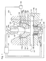
- Fig. 1 schematically shows the constitution of an optical disk molding apparatus 101 according to a first embodiment.
- the optical disk molding apparatus 101 is fundamentally constructed in a similar manner to the above-described conventional optical disk molding apparatus 1, the optical disk molding apparatus 101 is characterized in that a gas supply system is installed also to a fixed mold, a moving device for moving a movable mold is improved, and a controller 161 for controlling operations of each part constituting the apparatus to carry out the optical disk molding method to be detailed later is installed.
- the apparatus will be described in detail hereinbelow.
- the optical disk molding apparatus 101 is constituted as follows. Specifically, the optical disk molding apparatus 101 is roughly comprised of a nozzle 102 for injecting a molten resin plasticized to mold optical disks as molded objects, a fixed mold 104, and a movable mold 109. A cavity 112 to which the molten resin is injected thereby molding the molded object is formed between the fixed mold 104 and the movable mold 109.
- the nozzle 102 has an injection unit 131 installed thereto.
- the injection unit includes a plunger or a screw, and an arrangement necessary for injecting the plasticized molten resin.
- a nozzle moving device 132 To the nozzle 102 is connected a nozzle moving device 132 so that the nozzle 102 is movable back and forth to a recess part 113 to be described below along a thickness direction of the optical disk molded in the cavity 112.
- the above injection unit 131 and the nozzle moving device 132 are connected to a controller 161 and controlled to drive by the controller 161.
- a sprue bush 106 having the recess part 113 to which the nozzle 102 can move back and forth and a sprue part 107 for communicating the recess part 113 with the cavity 112 is attached to the fixed mold 104.
- the sprue bush 106 is positioned to the fixed mold 104 by being fitted to an inner circumferential face 105a of a locating ring 105 set to a fixed plate 103.
- the sprue part 107 is adapted to be concentric with the locating ring 105 and the nozzle 102 when the sprue bush 106 is fitted into the locating ring 105.
- the fixed mold 104 has a second gas passage 151 formed thereto with the utilization of a gap between the fixed mold and the sprue bush 106 and a gap part between the fixed mold and the fixed plate 103.
- One end of the second gas passage 151 is connected to a second gas supply device 152 installed outside the fixed mold 104, and the other end is opened to the cavity 112 circumferentially along the periphery of the sprue bush 106.
- the second gas supply device 152 which is connected to the controller 161 supplies, as will be discussed in detail later, the air according to the embodiment through the second gas passage 151 to a gap part between a mirror face 1041 of the fixed mold 104 and part of the optical disk so as to separate the mirror face 1041 and the optical disk from each other after the optical disk is molded.
- the mirror face 1041 is a flat face for forming a data non-form face 177 of the optical disk to be molded.
- a stamper 115 to which data to be transferred to the optical disk is formed is provided at the movable mold 109 to face the cavity 112. Similar to the stamper 15 described earlier, the stamper 115 is held to the movable mold 109 with an inner circumferential part 115a and an outer circumferential part 115b being caught by the movable mold 109.
- a mold moving device 136 for moving the movable mold 109 in the thickness direction of the optical disk molded in the cavity 112 is connected to the movable mold 109 for the purpose of the so-called mold opening operation and mold clamping operation.
- a toggle mechanism 1362 including an AC servo motor 1361 of an electric motor as a driving source and a ball screw is adopted for the mold moving device 136 in the embodiment.
- the movable mold 109 is moved by rotating the ball screw about an axis of the ball screw by the AC servo motor 1361.
- the movable mold 109 can hence be moved with an accuracy of a 1 ⁇ m level by the adoption of the electric motor type toggle mechanism 1362.
- a cylindrical cutter 117 is installed to the movable mold 109 correspondingly to a central part of the optical disk to be molded so as to form a through hole to the center of the optical disk after the molding.
- the cylindrical cutter 117 is moved by a cutter driving device 135 along the thickness direction of the optical disk.
- the movable mold 109 also has a first gas passage 110 cylindrically formed to the central part of the optical disk and inside the cylindrical cutter 117.
- a first gas supply device 134 is connected to the first gas passage 110 for supplying the air in the embodiment to the first gas passage 110. As will be detailed later, the first gas supply device 134 supplies the air through the first gas passage 110 to a gap part between the stamper and the optical disk to separate the stamper 115 and the optical disk after the optical disk is molded.
- a cylindrical ejector pin 111 is installed to the movable mold 109, which relatively moves in the thickness direction to the movable mold 109 thereby projecting to or being stored into the movable mold 109 when the movable mold 109 moves in the thickness direction.
- the above mold moving device 136, the cutter driving device 135, and the first gas supply device 134 are connected to the controller 161 and controlled to drive by the controller 161.
- the optical disk molding apparatus 101 further includes an optical disk take-out device 141 for taking out from within the fixed mold 104 and the movable mold 109 the optical disk molded and peeled subsequent to the mold opening operation of the movable mold 109 by the mold driving device 136.
- the optical disk take-out device 141 is connected to the controller 161 to be controlled in operation by the controller 161.
- the controller 161 drives the mold driving device 136 in a step (designated by "S" in the drawing) 1 to move the movable mold 109 in a direction of the mold opening operation which is the thickness direction of the molded optical disk 16.
- a move velocity of the movable mold 109 at this time is a first move velocity to be described later, i.e., 2-3mm/sec.
- the controller 161 drives the second gas supply device 152 at a time point when the movable mold moves in the mold opening direction by approximately 20 ⁇ m in the embodiment from a mold clamp state in which the optical disk is molded, thereby supplying the air through the second gas passage 151.
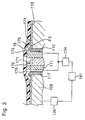
- a second release space part 176 is generated between part of the data non-form face 177 of the molded optical disk 16 and the mirror face 1041 of the fixed mold 104.
- the data non-form face 177 is exaggeratively illustrated for the sake of description in Fig. 7.
- the gas is supplied to the second release space part 176 at a time point when the second release space part 176 is formed.
- the data non-form face 177 and the mirror face 1041 are separated from each other all over with a pressure of the gas in a step 3.
- the air supply from the second gas supply device 152 is carried out with an air pressure of 39.2 x 10 4 Pa for 0.1 second.
- the above approximately 20 ⁇ m indicative of a timing for starting the air supply is a value set on the basis of the fact that a thickness tolerance of the optical disk 16 to be molded is ⁇ 10 ⁇ m. However, the value should be appropriately set in accordance with a change of an optical disk molding condition, etc.
- the reason for supplying the gas to the second release space part 176 when the second release space part 176 is generated, thereby totally separating the data non-form face 177 and the mirror face 1041 is as described below.
- the separation advances from the central part towards an outer circumferential part of the optical disk 16 and therefore, the outer circumferential part adheres to the mirror face 1041 until the end of the separation.
- a time while the molded optical disk 16 is kept in contact with the mold varies in a diametrical direction thereof during the separation process, bringing about a temperature difference to the optical disk 16 in the diametrical direction.
- the outer circumferential part of the optical disk 16 is not made transparently, but is hazed to raise problems in terms of an appearance and a quality of the optical disk.
- the above gas supply from the second gas supply device 152 is carried out when the second release space part 176 is formed, so that the data non-form face 177 and the mirror face 1041 are separated all at once, thus restricting the temperature difference to a minimum.
- the timing of starting the air supply can be considered as a timing whereat an appearance of the haze can be prevented.
- Controlling to start the above gas supply at the time point when the movable mold moves by a move amount of approximately 20 ⁇ m is enabled by adopting the toggle mechanism 1362 having the AC servo motor 1361 as the mold driving device 136 as described before, thereby enabling controlling a greatly minute move amount in comparison with the related art. Since the control of the minute move amount is enabled, the gas supply can be started at the same timing at all times in each separation operation for each optical disk and the quality can be uniformed in each optical disk.
- the gas supply from the second gas supply device 152 is started at the time point when the mold opening operation is performed to a predetermined position according to the present embodiment as above, and although it is likely to be inferior to the present embodiment in terms of the effect of uniforming the quality, an air pressure may be applied as a modified example to the second gas passage 151 by the second gas supply device 152 before the mold opening operation is performed.
- the air pressure to be applied is of a level whereby the second release space part 176 is formed when the movable mold moves, e.g., by the above approximately 20 ⁇ m.
- the pressure is, for example, 39.2 x 10 4 Pa mentioned before.
- the phenomenon of the appearance of haze is easy to take place particularly when the stamper 115 is provided at the movable mold 109.
- the stamper 115 is therefore preferably provided at the fixed mold 104 to avoid the problem of the appearance of haze as will be discussed later.
- a step 4 the movable mold 109 is further moved in the mold opening direction to a preset origin position.
- the move velocity at this time is a second move speed to be described later which exceeds the above first move velocity, namely, 200-300mm/sec.
- the movable mold 109 is opened further from the origin position by a move distance of 0.3mm or smaller, that is, exceeding 0 and not larger than 0.3mm.
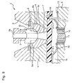
- the ejector pin 111 projects from a storage position 171 where the pin is stored in the movable mold 109 by the above move distance 172 out of the movable mold 109.
- a value of the illustrated move distance 172 becomes the aforementioned "exceeding 0 and not larger than 0.3mm".
- the controller 161 sets the move velocity of the movable mold 109 when the second release space part 176 is formed and the first move velocity when the movable mold is moved by the above move distance 172 to be approximately 1% an output of the AC servo motor of the mold moving device 136, i.e., 2-3mm/sec in the present embodiment.
- a first release space part 175 which is a gap of a minute amount is formed to the central part of the optical disk 16 between a data transferred face 173 of the optical disk 16 and a data forming face 174 of the stamper 115. Since a size in the thickness direction is smaller in a state when the first release space part 175 is formed, that is, in a state when the movable mold 109 is opened by the controller 161 by the above move distance 172 of "exceeding 0 and not larger than 0.3mm” than a gap part formed in the related art, the deformation of the stamper 15 as described with reference to Fig.
- An angle ⁇ 2 between the data transferred face 173 of the optical disk 16 and the data forming face 174 of the stamper 115 having pits and projections becomes smaller than the angle ⁇ 1 shown in Fig. 9.
- the data transferred face 173 is accordingly allowed to slip nearly in the thickness direction of the optical disk from the data forming face 174, so that side faces of projecting parts formed to the data transferred face 173 are prevented from being rubbed and deformed by the projecting parts of the data forming face 174. Correct data can be formed to the optical disk 16 and the quality deterioration of the optical disk is not occurred.
- the controller 161 drives the first gas supply device 134 in a step 5 after the mold opening operation of the movable mold 109 with the above move distance 172, thereby supplying the air to the formed first release space part 175. At this time, the controller 161 controls the pressure of the air to be supplied to not smaller than 24.5 x 10 4 Pa.
- the controller 161 drives again the mold moving device 136 to move the movable mold 109 in the mold opening direction.
- the controller 161 moves the movable mold 109 at this time at the second move velocity faster than the first move velocity to finish the opening.
- the second move velocity is approximately 100% the output of the AC servo motor of the mold moving device 136, i.e., 200-300mm/sec in the embodiment. Since the electric motor type toggle mechanism is used as the mold moving device 136 in the embodiment as described above, the first move velocity and the second move velocity vary depending on the structure of the mechanism. For instance, the second move velocity can be set to approximately 350mm/0.4sec.
- the controller 161 drives the take-out device 141 thereby taking out the optical disk 16 from between the fixed mold 104 and the movable mold 109.
- the controller 161 operates the mold moving device 136 thereafter to move the movable mold 109 in a mold clamp direction and then returns to the molding operation for optical disks.
- the move distance 172 of "exceeding 0 and not larger than 0.3mm" and the pressure of the air supplied to the first release space part 175 of 24.5 x 10 4 Pa or larger are based on grounds as will be described with reference to Fig. 4.
- a circle mark represents nonexistence of the deformation at the data transferred face 173 of the optical disk 16 and an "X" mark represents existence of the deformation.
- the data transferred face 173 of the optical disk 16 is not deformed when the pressure of the air to be supplied to the first release space part 175 is not smaller than 24.5 x 10 4 Pa while the move distance 172 is 0.1mm, the data transferred face 173 is not deformed when the pressure of the air to be supplied to the first release space part 175 is not smaller than 24.5 x 10 4 Pa while the move distance 172 is 0.2mm, and the data transferred face 173 is not deformed when the pressure of the air to be supplied to the first release space part 175 is not smaller than 34.3 x 10 4 Pa while the move distance 172 is 0.3mm.
- the data transferred face 173 of the optical disk 16 is deformed regard-less of the pressure of the supplied air to the first release space part 175 when the move distance 172 is 0.5mm.
- the move distance 172 of "exceeding 0 and not larger than 0.3mm" and the pressure of the air to be supplied to the first release space part 175 of 24.5 x 10 4 Pa or larger as described above are obtained.
- An upper limit of the air pressure is approximately 49 x 10 4 Pa in the present embodiment which is based on a pressure of the air supplied to a place where the optical disk molding apparatus is seated and which is determined according to a change of the pressure at the seated place.
- the opening operation of the movable mold 109 is temporarily stopped after the movement of the movable mold 109 in the step 4 and the air is supplied to the first release space part 175, and thereafter the movable mold 109 is opened in the step 7 again.
- the control is not limited to this way, and the opening operation of the movable mold 109 can be performed continuously from the step 4 to the step 7 without the temporary stop in the halfway.
- the move distance 172 applies to the case where the optical disk for RAM is molded.
- the move distance 172 can be approximately 0.1mm and the gas is supplied with the pressure of approximately 19.6 x 10 4 Pa for about 0.5-1.0 second.
- a difference in the move distance 172 between the RAM and the ROM results from a difference in structure of the optical disks. That is, the optical disk for RAM has a data record part formed of continuous projection parts and pit parts along the circumferential direction thereof, and therefore the gap between the stamper 115 and the optical disk 16, i.e., the above move distance 172 should be secured large to facilitate flowing the supplied gas in the diametrical direction of the optical disk 16.
- the optical disk for ROM since the optical disk for ROM has a data record part formed of discontinuous pit parts, namely, pits formed at intervals along the circumferential direction, there are gaps arranged towards the outer circumference. Therefore the supplied gas flows in the diametrical direction of the optical disk 16 even if the move distance 172 is made smaller than in the case of RAM.
- the stamper 115 is provided at the fixed mold 104 in the structure of an optical disk forming apparatus 201 shown in Fig. 5 of a second embodiment.
- the ejector pin 111, the cylindrical cutter 117 and the first gas passage 110 of the movable mold 109 are slightly made different in arrangement from in the foregoing optical disk forming apparatus 101, the difference will not constitute a specific feature.
- operation opposite to the operation in the optical disk forming apparatus 101 is carried out regarding the release of the optical disk described with reference to Fig. 3. That is, steps 4-6 are carried out first and steps 1-3 are carried out next.
- the movable mold 109 is moved in the mold opening direction with the move distance 172 from the mold clamp state, thereby forming the first release space part 175 to a gap between the data forming face 174 of the stamper 115 provided at the fixed mold 104 and part of the data transferred face 173 of the optical disk 16, e.g., the central part of the optical disk.
- the air is supplied from the second gas supply device 152 to the first release space part 175 similar to the case where the air is supplied from the first gas supply device 134 to the first release space part 175, whereby the data transferred face 173 of the optical disk 16 and the data forming face 174 of the stamper 115 are wholly separated from each other.
- the second release space part 176 is generated between the data non-form face 177 of the optical disk 16 and part of a mirror face 1091 of the movable mold 109 corresponding to the above mirror face 1041 by moving the movable mold 109 and pushing by the ejector pin 111 through the relative movement.
- the air is supplied from the first gas supply device 134 to the second release space part 176 similar to the case of supplying the air from the second gas supply device 152 to the second release space part 176, thereby separating the data non-form face 177 of the optical disk 16 and the mirror face 1091 of the movable mold 109 all over the faces.
- the stamper 115 When the stamper 115 is mounted to the fixed mold 104, as described above, the data transferred face 173 of the optical disk 16 and the data forming face 174 of the stamper 115 are first totally released, and the optical disk 16 is cooled by the release. Therefore, the control on the move amount for generating the second release space part 176 to avoid the above-described appearance of haze is not particularly needed although it may be executed. Accordingly in the structure with the stamper 115 provided at the fixed mold 104, an effect of eliminating the need of the control for preventing the appearance of haze can be obtained in addition to the effect of preventing the quality deterioration. When the fixed mold 104 is positioned in a direction opposite to the gravity to the movable mold 104 as in the present second embodiment, further an effect that dust or the like falling, for example, from the nozzle 102 is hard to affect is obtained.
- the optical disk forming apparatus 101 of the first embodiment and the optical disk forming apparatus 201 of the second embodiment described above are so-called cold runner types without having a heating device installed to a portion of the sprue bush part 106.
- a hot runner type with the heating device can be adopted as shown in Fig. 6.
- Fig. 6 shows an optical disk forming apparatus 211 obtained by turning the above optical disk forming apparatus 201 into the hot runner type.
- a coil 213 for heating of, e.g., an electromagnetic induction type is buried in a sprue bush 212 corresponding to the sprue bush 106, and also a coolant path 215 is formed through which, for example, water is fed to cool the sprue bush 212 if temperature of the sprue bush extraordinarily increases.
- the heating coil 213 is connected to a power source device 214 and the power source device 214 is controlled in operation by the controller 161.
- a coolant supply device 216 which at least supplies the coolant and is controlled in operation by the controller 161 is connected to the coolant path 215.
- the temperature of the sprue bush 212 is controlled by controlling operation of the power source device 214 and the coolant supply device 216 by the controller 161.
- the gas is supplied both to the first release space part 175 formed between part of the data transferred face 173 of the optical disk 16 and the data forming face 174 of the stamper 115 and to the second release space part 176 formed between the data non-form face 177 of the optical disk 16 and the mirror face of the mold.
- the gas is supplied to at least one of the spaces, more preferably, the gas is supplied at least to the first release space part 175.
Landscapes
- Engineering & Computer Science (AREA)
- Manufacturing & Machinery (AREA)
- Mechanical Engineering (AREA)
- Moulds For Moulding Plastics Or The Like (AREA)
- Manufacturing Optical Record Carriers (AREA)
Abstract
Description
the gas supply device has a second gas supply device for supplying the gas to the second release space part so as to separate totally the data non-form face and the mold from each other with the pressure of the gas.
the stamper is fitted to the movable mold, and
the controller further makes the mold moving device move the movable mold from the mold clamp state with a move amount by which the second release space part is formed and which is smaller than a move amount for forming a first release space part by releasing part of the optical disk from the stamper, and makes the second gas supply device work to supply the gas to the second release space part at the time point when the second release space part is formed.
Claims (22)
- An optical disk molding apparatus having a pair of molds (104, 109) to open and clamp in which a stamper (115) having data to be transferred to an optical disk to be molded with the molds is provided at a cavity (112) in the molds, and molding the optical disk in the cavity and opening the molds after molding the optical disk, the apparatus being characterized by comprising:a mold moving device (136) having an electric motor (1361) for the opening of the molds; anda gas supply device (134, 152) for supplying a gas to a release space part (175, 176) formed by releasing part of the molded optical disk from the mold by the opening by the mold moving device so as to separate totally the optical disk and the mold from each other with a pressure of the gas.
- The optical disk molding apparatus according to claim 1, wherein the release space part has a first release space part (175) formed by releasing part of the optical disk from the stamper, and the gas supply device has a first gas supply device (134) for supplying the gas to the first release space part so as to separate totally the optical disk and the stamper from each other with the pressure of the gas,
said apparatus further comprising a controller (161) for controlling to drive the mold moving device and the first gas supply device, which makes the mold moving device open the molds to separate the stamper and the optical disk with a move distance (172) not damaging a data transferred face (173) of the optical disk from a mold clamp state in which the optical disk is molded so as to form the first release space part, and makes the first gas supply device work to supply the gas to the first release space part at a time point when the first release space part is formed. - The optical disk molding apparatus according to claim 2, wherein the move distance with which the controller makes the mold moving device open the molds is a mold open amount of 0.3mm or smaller exceeding the mold clamp state.
- The optical disk molding apparatus according to claim 1, wherein the controller makes the gas supply device supply the gas with a pressure of 24.5 x 10⁴ Pa or larger.
- The optical disk molding apparatus according to claim 2, wherein the controller makes the gas supply device supply the gas with a pressure of 24.5 x 10⁴ Pa or larger.
- The optical disk molding apparatus according to claim 3, wherein the controller makes the gas supply device supply the gas with a pressure of 24.5 x 10⁴ Pa or larger.
- The optical disk molding apparatus according to claim 1, wherein the release space part has a second release space part (176) formed by releasing part of a data non-form face (177) opposite to a data transferred face (173) of the molded optical disk from the mold by the opening by the mold moving device, and
the gas supply device has a second gas supply device (152) for supplying the gas to the second release space part so as to separate totally the data non-form face and the mold from each other with the pressure of the gas. - The optical disk molding apparatus according to claim 2, wherein the release space part has a second release space part (176) formed by releasing part of a data non-form face (177) opposite to the data transferred face (173) of the molded optical disk from the mold by the opening by the mold moving device, and
the gas supply device has a second gas supply device (152) for supplying the gas to the second release space part so as to separate totally the data non-form face and the mold from each other with the pressure of the gas. - The optical disk molding apparatus according to claim 6, wherein the release space part has a second release space part (176) formed by releasing part of a data non-form face (177) opposite to a data transferred face (173) of the molded optical disk from the mold by the opening by the mold moving device, and
the gas supply device has a second gas supply device (152) for supplying the gas to the second release space part so as to separate totally the data non-form face and the mold from each other with the pressure of the gas. - The optical disk molding apparatus according to claim 1, wherein the molds have a movable mold (109) movable by the mold moving device along a thickness direction of the optical disk to be molded and a fixed mold (104) arranged opposite to the movable mold, and the stamper is fitted to the fixed mold.
- The optical disk molding apparatus according to claim 2, wherein the molds have a movable mold (109) movable by the mold moving device along a thickness direction of the optical disk to be molded and a fixed mold (104) arranged opposite to the movable mold, and the stamper is fitted to the fixed mold.
- The optical disk molding apparatus according to claim 6, wherein the molds have a movable mold (109) movable by the mold moving device along a thickness direction of the optical disk to be molded and a fixed mold (104) arranged opposite to the movable mold, and the stamper is fitted to the fixed mold.
- The optical disk molding apparatus according to claim 7, wherein the molds have a movable mold (109) movable by the mold moving device along a thickness direction of the optical disk to be molded and a fixed mold (104) arranged opposite to the movable mold, and the stamper is fitted to the fixed mold.
- The optical disk molding apparatus according to claim 8, wherein the molds have a movable mold (109) movable by the mold moving device along a thickness direction of the optical disk to be molded and a fixed mold (104) arranged opposite to the movable mold, and the stamper is fitted to the fixed mold.
- The optical disk molding apparatus according to claim 9, wherein the molds have a movable mold (109) movable by the mold moving device along a thickness direction of the optical disk to be molded and a fixed mold (104) arranged opposite to the movable mold, and the stamper is fitted to the fixed mold.
- The optical disk molding apparatus according to claim 7, wherein the molds have a movable mold (109) movable by the mold moving device along a thickness direction of the optical disk to be molded and a fixed mold (104) arranged opposite to the movable mold,
the stamper is fitted to the movable mold, and
the controller further makes the mold moving device move the movable mold from the mold clamp state with a move amount by which the second release space part is formed and which is smaller than a move amount for forming a first release space part (175) by releasing part of the optical disk from the stamper, .and makes the second gas supply device work to supply the gas to the second release space part at the time point when the second release space part is formed. - The optical disk molding apparatus according to claim 8, wherein the molds have a movable mold (109) movable by the mold moving device along a thickness direction of the optical disk to be molded and a fixed mold (104) arranged opposite to the movable mold,
the stamper is fitted to the movable mold, and
the controller further makes the mold moving device move the movable mold from the mold clamp state with a move amount by which the second release space part is formed and which is smaller than a move amount for forming a first release space part (175) by releasing part of the optical disk from the stamper, and makes the second gas supply device work to supply the gas to the second release space part at the time point when the second release space part is formed. - The optical disk molding apparatus according to claim 9, wherein the molds have a movable mold (109) movable by the mold moving device along a thickness direction of the optical disk to be molded and a fixed mold (104) arranged opposite to the movable mold,
the stamper is fitted to the movable mold, and
the controller further makes the mold moving device move the movable mold from the mold clamp state with a move amount by which the second release space part is formed and which is smaller than a move amount for forming a first release space part (175) by releasing part of the optical disk from the stamper, and makes the second gas supply device work to supply the gas to the second release space part at the time point when the second release space part is formed. - An optical disk molding method having molding an optical disk, and opening a pair of molds (104, 109) after molding the disk; the molds being opened and clamped, and having a cavity (112) with a stamper (115) which is provided at the cavity and which has data to be transferred to the optical disk to be molded with the molds,
said method being characterized by comprising:opening the molds so as to separate the stamper and the optical disk from a mold clamp state in which the optical disk is molded with a move distance (172) of 0.3mm or smaller exceeding the mold clamp state and not damaging a data transferred face (173) of the optical disk; andsupplying a gas to a first release space part (175) at a time point when the first release space part is formed between part of the optical disk and the stamper by releasing the optical disk from the stamper by the opening of the molds, and then separating totally the optical disk and the stamper from each other. - The optical disk molding method according to claim 19, wherein the gas is supplied to the first release space part with a pressure of 24.5 x 10⁴ Pa or larger.
- The optical disk molding method according to claim 19, further comprising:forming a second release space part (176) by releasing part of a data non-form face (177) opposite to the data transferred face (173) of the molded optical disk from the mold due to the opening of the molds before forming the first release space part;separating totally the data non-form face and the mold from each other by supplying a gas to the second release space part at a time point when the second release space part is formed; andforming the first release space part after the total separation of the data non-form face and the mold from each other, thereby totally separating the optical disk and the stamper from each other.
- The optical disk molding method according to claim 20, further comprising:forming a second release space part (176) by releasing part of a data non-form face (177) opposite to the data transferred face (173) of the molded optical disk from the mold due to the opening of the molds before forming the first release space part;separating totally the data non-form face and the mold from each other by supplying a gas to the second release space part at a time point when the second release space part is formed; andforming the first release space part after the total separation of the data non-form face and the mold from each other, thereby totally separating the optical disk and the stamper from each other.
Applications Claiming Priority (3)
| Application Number | Priority Date | Filing Date | Title |
|---|---|---|---|
| JP6625599 | 1999-03-12 | ||
| JP6625599 | 1999-03-12 | ||
| PCT/JP2000/001455 WO2000054957A1 (en) | 1999-03-12 | 2000-03-10 | Optical disk molding device and method |
Publications (2)
| Publication Number | Publication Date |
|---|---|
| EP1213120A1 true EP1213120A1 (en) | 2002-06-12 |
| EP1213120A4 EP1213120A4 (en) | 2002-10-16 |
Family
ID=13310584
Family Applications (1)
| Application Number | Title | Priority Date | Filing Date |
|---|---|---|---|
| EP00907987A Withdrawn EP1213120A4 (en) | 1999-03-12 | 2000-03-10 | MOLDING DEVICE AND METHOD FOR OPTICAL DISC |
Country Status (5)
| Country | Link |
|---|---|
| US (1) | US6875378B1 (en) |
| EP (1) | EP1213120A4 (en) |
| JP (1) | JP4179751B2 (en) |
| CN (1) | CN1343160A (en) |
| WO (1) | WO2000054957A1 (en) |
Families Citing this family (2)
| Publication number | Priority date | Publication date | Assignee | Title |
|---|---|---|---|---|
| JP4593572B2 (en) * | 2004-11-18 | 2010-12-08 | パナソニック株式会社 | Injection molding apparatus, injection molding method and injection mold |
| JP2018085154A (en) * | 2016-11-21 | 2018-05-31 | パナソニックIpマネジメント株式会社 | Disk tray and tray holder |
Family Cites Families (20)
| Publication number | Priority date | Publication date | Assignee | Title |
|---|---|---|---|---|
| CA1196458A (en) * | 1981-10-08 | 1985-11-12 | Yoshihiko Yamazaki | Injection molding machine |
| JPS60174623A (en) | 1984-02-21 | 1985-09-07 | Toshiba Mach Co Ltd | Injection molding machine |
| JPS62181118A (en) * | 1986-02-05 | 1987-08-08 | Showa Denko Kk | mold for molding |
| JP2630606B2 (en) | 1987-12-17 | 1997-07-16 | ティーディーケイ株式会社 | Molding equipment for optical disks, etc. |
| US5316466A (en) | 1987-12-24 | 1994-05-31 | Tdk Corporation | Disc molding apparatus |
| JPH02147221A (en) * | 1988-11-29 | 1990-06-06 | Canon Inc | Disc forming equipment |
| US4988273A (en) * | 1989-06-23 | 1991-01-29 | Cincinnati Milacron Inc. | Injection molding machines having a brushless DC drive system |
| JPH05314546A (en) | 1992-05-12 | 1993-11-26 | Hitachi Maxell Ltd | Optical disk substrate manufacturing method |
| JPH0631782A (en) | 1992-07-14 | 1994-02-08 | Kuraray Co Ltd | Optical information recording medium substrate manufacturing apparatus and manufacturing method |
| US5376317A (en) * | 1992-12-08 | 1994-12-27 | Galic Maus Ventures | Precision surface-replicating thermoplastic injection molding method and apparatus, using a heating phase and a cooling phase in each molding cycle |
| US5840352A (en) * | 1993-09-06 | 1998-11-24 | Fuji Photo Film Co., Ltd. | Fresnel lens manufacturing apparatus |
| JPH07290527A (en) | 1994-04-25 | 1995-11-07 | Ricoh Co Ltd | Optical disc substrate peeling method and take-out device |
| JPH0825434A (en) | 1994-07-20 | 1996-01-30 | Mitsubishi Chem Corp | Molding method for disk substrate |
| JPH0890617A (en) | 1994-09-20 | 1996-04-09 | Taiyo Yuden Co Ltd | Disk-molding method |
| JPH08207161A (en) | 1995-02-03 | 1996-08-13 | Ricoh Co Ltd | Optical disc molding machine |
| US5810941A (en) * | 1995-07-14 | 1998-09-22 | Moynagh; Kelan Thomas | Cleaning method for high precision molding components |
| JP3160837B2 (en) | 1995-12-12 | 2001-04-25 | 株式会社名機製作所 | Disk molding die and molding method thereof |
| JP3224347B2 (en) * | 1996-11-28 | 2001-10-29 | 株式会社名機製作所 | Mold for forming disc substrates |
| JP3040386B2 (en) | 1997-12-25 | 2000-05-15 | 日精樹脂工業株式会社 | Injection mold for disk substrate |
| JP2000108169A (en) | 1998-10-09 | 2000-04-18 | Matsushita Electric Ind Co Ltd | Mold opening method and temporary opening stop mold |
-
2000
- 2000-03-10 JP JP2000605014A patent/JP4179751B2/en not_active Expired - Fee Related
- 2000-03-10 CN CN00804900A patent/CN1343160A/en active Pending
- 2000-03-10 EP EP00907987A patent/EP1213120A4/en not_active Withdrawn
- 2000-03-10 WO PCT/JP2000/001455 patent/WO2000054957A1/en not_active Ceased
- 2000-03-10 US US09/936,164 patent/US6875378B1/en not_active Expired - Fee Related
Also Published As
| Publication number | Publication date |
|---|---|
| JP4179751B2 (en) | 2008-11-12 |
| CN1343160A (en) | 2002-04-03 |
| WO2000054957A1 (en) | 2000-09-21 |
| EP1213120A4 (en) | 2002-10-16 |
| US6875378B1 (en) | 2005-04-05 |
Similar Documents
| Publication | Publication Date | Title |
|---|---|---|
| KR860001333B1 (en) | Flow control method of hot water valve assembly, mold assembly and disk forming material for injection molding machine | |
| JPS6023970B2 (en) | valve assembly | |
| JPH0675888B2 (en) | Disk injection molding method | |
| KR860000802B1 (en) | Hot sprue assembly for an injection molding machine | |
| US20030147987A1 (en) | Disk substrate, molding apparatus for injection-molding it and disk substrate pick-up robot | |
| JP4263008B2 (en) | INJECTION MOLDING APPARATUS FOR MANUFACTURING DISK SUBSTRATE AND METHOD FOR MANUFACTURING DISK SUBSTRATE | |
| JP3294971B2 (en) | Disc substrate and mold for molding the same | |
| EP1213120A1 (en) | Optical disk molding device and method | |
| JP2003220634A (en) | Molding equipment for molding | |
| JPH09295319A (en) | Mold for molding disk substrate | |
| JPH0890624A (en) | Disk substrate molding die | |
| JPWO2000054957A1 (en) | Optical disc molding device and method | |
| JPH09314563A (en) | Mold device for molding disk-shaped recording medium substrate | |
| JP2003220633A (en) | Molding equipment for molding | |
| US20070176311A1 (en) | Mold for molding disk, adjustment member, and method of molding disk substrate | |
| JPH0687142A (en) | Optical disk substrate, its injection molding apparatus and injection molding method | |
| JP3160837B2 (en) | Disk molding die and molding method thereof | |
| JP3087270B2 (en) | Molding equipment for molding | |
| JP2003053786A (en) | Injection molding equipment for resin substrate molding | |
| JP2004148667A (en) | Mold for forming disc plate | |
| JPH08129847A (en) | Mold for disk substrate with hub | |
| JPH1125451A (en) | Magnetic disk | |
| JP2002154142A (en) | Method and device for molding | |
| JP2002192576A (en) | Optical disk molding die apparatus and adjustment method thereof | |
| JPH0536657Y2 (en) |
Legal Events
| Date | Code | Title | Description |
|---|---|---|---|
| PUAI | Public reference made under article 153(3) epc to a published international application that has entered the european phase |
Free format text: ORIGINAL CODE: 0009012 |
|
| 17P | Request for examination filed |
Effective date: 20011012 |
|
| AK | Designated contracting states |
Kind code of ref document: A1 Designated state(s): DE |
|
| A4 | Supplementary search report drawn up and despatched |
Effective date: 20020829 |
|
| AK | Designated contracting states |
Kind code of ref document: A4 Designated state(s): DE |
|
| RIC1 | Information provided on ipc code assigned before grant |
Free format text: 7B 29C 45/43 A, 7B 29C 45/26 B, 7B 29C 45/70 B |
|
| STAA | Information on the status of an ep patent application or granted ep patent |
Free format text: STATUS: THE APPLICATION IS DEEMED TO BE WITHDRAWN |
|
| 18D | Application deemed to be withdrawn |
Effective date: 20021228 |
|
| RBV | Designated contracting states (corrected) |
Designated state(s): DE |