EP1211859A2 - Fixed-point DSP implementation of FM demodulation and decoding - Google Patents
Fixed-point DSP implementation of FM demodulation and decoding Download PDFInfo
- Publication number
- EP1211859A2 EP1211859A2 EP01000608A EP01000608A EP1211859A2 EP 1211859 A2 EP1211859 A2 EP 1211859A2 EP 01000608 A EP01000608 A EP 01000608A EP 01000608 A EP01000608 A EP 01000608A EP 1211859 A2 EP1211859 A2 EP 1211859A2
- Authority
- EP
- European Patent Office
- Prior art keywords
- signal
- value
- bbmux
- pilot
- look
- Prior art date
- Legal status (The legal status is an assumption and is not a legal conclusion. Google has not performed a legal analysis and makes no representation as to the accuracy of the status listed.)
- Withdrawn
Links
Images


Classifications
-
- H—ELECTRICITY
- H04—ELECTRIC COMMUNICATION TECHNIQUE
- H04L—TRANSMISSION OF DIGITAL INFORMATION, e.g. TELEGRAPHIC COMMUNICATION
- H04L27/00—Modulated-carrier systems
- H04L27/18—Phase-modulated carrier systems, i.e. using phase-shift keying
- H04L27/22—Demodulator circuits; Receiver circuits
- H04L27/233—Demodulator circuits; Receiver circuits using non-coherent demodulation
- H04L27/2338—Demodulator circuits; Receiver circuits using non-coherent demodulation using sampling
-
- H—ELECTRICITY
- H04—ELECTRIC COMMUNICATION TECHNIQUE
- H04H—BROADCAST COMMUNICATION
- H04H40/00—Arrangements specially adapted for receiving broadcast information
- H04H40/18—Arrangements characterised by circuits or components specially adapted for receiving
- H04H40/27—Arrangements characterised by circuits or components specially adapted for receiving specially adapted for broadcast systems covered by groups H04H20/53 - H04H20/95
- H04H40/36—Arrangements characterised by circuits or components specially adapted for receiving specially adapted for broadcast systems covered by groups H04H20/53 - H04H20/95 specially adapted for stereophonic broadcast receiving
- H04H40/45—Arrangements characterised by circuits or components specially adapted for receiving specially adapted for broadcast systems covered by groups H04H20/53 - H04H20/95 specially adapted for stereophonic broadcast receiving for FM stereophonic broadcast systems receiving
Definitions
- DSPs digital signal processors
- the BBMUX signal consists of the L+R, the pilot and the AM modulated L-R signals. These signals are multiplexed and filtered.
- the L-R signal is modulated with a carrier frequency such as for example 38 KHz and then added to the L-R channel with a pilot frequency such as a 19 KHz pilot signal and put out on the airways in the form of the signal discussed in the Equation 1) above.
- the transmitted composite FM stereo signal is then received by a radio or other receiver, demodulated and then decoded to obtain the Left and Right information channels.
- demodulation of FM signals by digital circuitry such as Digital Signal Processors (DSP) is more readily accomplished if the conventional signal is converted to a complex baseband FM signal having a real portion (RL) and an imaginary or quadrature portion (IM).
- Figure 1 illustrates typical circuitry for this conversion.
- an FM signal at baseband, or zero frequency is the result of "mixing out” the carrier frequency from the FM signal, as shown in Figure 1.
- the generation of complex data is the result of mixing FM signal with a cosine and sine local oscillator (LO), and the process can be derived mathematically by using the complex version of the FM equation.
- the mixing process is a simple multiplication of signals where the cosine mixing term and sine mixing term are multiplied with the incoming FM signal. For baseband results, both mixers oscillate at the FM carrier frequency ? c . As shown, the total mixing operation produces a real (in-phase) and imaginary (quadrature-phase baseband component.
- X(t) FM baseband signal is equal to Equation 5) + Equation 7) which can be reduced to 8)
- X(t) FM (A c /2)(e j ⁇ (t) )
- Equation 8 the complex equation for an FM signal at baseband, a complex-valued FM sample can be represented by a vector on the complex unit circle having an amplitude and a phase angle.
- a complex sample gives two pieces of information, a real and imaginary component.
- Equation 9 The polar form of a complex number, shown in Equation 9, can be used to extract the phase angle of a complex sample. Each incoming complex sample will have a new amplitude and phase angle. Since FM signals store all of their information in the phase, it is seen that the phase angle is the information required to demodulate a complex-sampled FM signal.
- each consecutive sample can be represented as a vector rotating around the complex unit circle.
- Equation 12 is used to directly relate the phase difference between two complex-valued samples.
- each successive vector will travel 180° from the last vector's position.
- typical fixed point DSPs FP DSP
- FP DSP fixed point DSP
- other various methods must be used to accomplish these calculations in the commercial or typical DSP, such as for example TI's fixed point DSP TM5320C6201.
- a demodulation signal can be obtained which has an excellent signal to noise ratio. That is, the resulting BBMUX signal is almost identical to that calculated by the Newton-Raphson method and perhaps superior to the "conditional subtraction.”
- BBMUX FM base-band multiplex
- This step is illustrated in Figure 1 as producing a real (RL) in-phase base-band component on line 12 and an imaginary (IM) quadrature-phase base-band component on line 14 as was discussed above by mixing or multiplying the received FM signal by the sine and cosine terms as indicated at mixers 16 and 18.
- the circuit will also typically include LPF (filters) 20 and 22.
- Figure 4A represents the conventional BBMUX signal before being converted to a complex signal
- Figures 4B and 4C illustrate the imaginary or quadrature and real components of the signal respectively as an output on lines 12 and 14. It is this quadrature and imaginary signals that is applied to the DSP for demodulation and decoding.
- a conventional FM signal includes left and right stereo signals mixed with an FM carrier and transmitted over the air waves or through a wire medium and then converted to the quadrature and real components by methods well known in the art.
- the real and quadrature portions of the signal will be provided to the DSP circuitry for demodulation and decoding.
- the demodulation process continues in the DSP as discussed above with respect to Equations 5 through 11, which as can be seen from Equation 11 requires the calculation of X/Y or actually IM/RL. Since a fixed point DSP typically does not include dedicated circuitry for performing such division, it is well know in the art to use other techniques. Such other techniques include the "conditional subtraction” technique or the use of the Newton-Raphson method if very accurate results are desired. There is also a third method, which is the fastest, but requires a look-up table for the value of 1/RL. That is, the reciprocal value of RL. Once the value of 1/RL is determined, that value is then multiplied by the value of IM of the signal.
- the value of RL will be determined by the value of the cosine T as T varies from 0 to 2 p.
- the value of cosine T when evaluated between the entire range of 0 to 2 p will vary from -1 to +1 and consequently, includes extremely small values as it passes through the zero value between -1 and +1. Consequently, it is seen that the prior art method of using a look-up table for the reciprocal of 1/RL to perform the division calculation of IM over RL, although faster than the other two methods, has a major disadvantage of requiring an extremely large look-up table or set of values because of the very small numbers generated in the denominator as the values pass through zero.
- the fact that the RL value is an in-phase representation allows the RL part or value to be manipulated in such a way so as to solve this difficult problem of having a look-up table for very small values. More specifically, and as shown in step 34 of Figure 2, by adding a numeral value N to the value of RL (which it will be appreciated, RL ranges from -1 to +1) before calculating the reciprocal value (i.e. 1/RL + N) will provide a significant change from the original value of 1/RL. For example, as mentioned above, since RL varied between -1 to +1, the reciprocal value of 1/RL also ranges from -1 to +1, and therefore, the look-up table must include values that approach and pass through zero.
- the final value of 1/RL+2 will range from 1 to 1/3 and does not go through zero. Therefore, it is seen that there are no values less than 1/3 and no values greater than 1. Therefore, the size of the look-up table indicated at step 36 of Figure 2A may be significantly reduced since the values do not pass through zero and there are no extremely small values. It will also be appreciated that the value of N in the equation 1/RL + N is preferably chosen to be the integer 2 as this provides the simplest and most effective results.
- N may be used advantageously, but if the value of N varies much from the value of 2, the range between the highest value to the lowest value begins to increase significantly thereby again increasing the size of the look-up table. For example, if the value of one (1) was added rather than two (2), the denominator would again go to 0 and consequently the value would increase to infinity, which would make the computations just as difficult as if the number one (1) had not been added. Likewise, if values much greater than 2 are added to RL in the 1/RL function, the separation between the maximum and minimum values decreases. This means that smaller and smaller numbers must be used to distinguish between different values.
- the range is substantially shifted and if N is chosen to be a value between about 1.1 and 5, the problem of having a look-up table with very small values will be solved.
- the arctangent of the resulting value is then determined as indicated at step 38 of Figure 2A. That arctangent value is preferably also determined by referring to a look-up table.
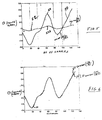
- curve 50 represents the magnitude of BBMUX determined by solving for the arctan of IM/RL when computed in the typical and prior art techniques of using Newton-Raphson, conditional subtraction, or a very large look-up table for 1/RL.
- the curve 52 which has an amplitude that varies to a much smaller degree around the zero base line, but has the same shape as curve 50.
- the curve 52 is the magnitude of BBMUX determined by solving for the arctan of IM/RL+2.
- Figure 6 we have the same curve 50 determined by solving the arctangent of X/Y (IM/RL) as displayed in Figure 5.
- the look-up table does not go through zero and consequently does not have very small values, memory is saved and the number of cycles required to complete the calculation is reduced considerably which, of course, increases the speed of the computations.
- the DSP will be programmed for decoding using the non-coherent scheme similar to the scheme disclosed in U.S. patent 5,239,585 issued to Randall C. Restle.
- the non-coherent scheme is described below.
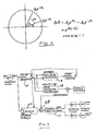
- Figure 7 shows a block diagram of the non-coherent scheme described by Utter.
- the non-coherent scheme is based on performing Discrete Fourier Transform (DFT) snapshots of the composite signal samples that are provided by an analog to digital converter (ADC) at a sample rate equal to 8 times the pilot frequency. It will be recalled that in the example discussed earlier, the pilot frequency was 19 KHz. The DFT is calculated only at the pilot frequency of 19 KHz.
- DFT Discrete Fourier Transform
- the pilot's signal phase angle is then acquired from the resulting DFT snapshots.
- the phase angle is used to select an appropriate polyphase interpolation filter bank in a manner known by those skilled in the art.
- the interpolation filtering is then performed to extract the left and right audio signals from the composite signal.
- the left and right audio signals are then output to a digital to analog converter (DAC).
- DAC digital to analog converter
- the signal is then up-sampled by a factor U and a polyphase interpolator filter is applied to the signal in order to interpolate what the value of the incoming signal was at those instances when the pilot signal was at 45°, 135°, 225° or 315°.
- a polyphase interpolator filter is applied to the signal in order to interpolate what the value of the incoming signal was at those instances when the pilot signal was at 45°, 135°, 225° or 315°.
- I and Q are the in-phase (real) and the quadrature (imaginary) components of the pilot respectively.
- the pilot signal's frequency may deviate by as much as 2 Hz, which corresponds to a phase drift rate of 720°/sec. At this rate, it would take 8.93 msecs to drift 6.43°. At a sample rate of 152 KHz, this would be equivalent to approximately 1357 signal samples. Therefore, the DFT snapshot rate is chosen to be greater than 1 snapshot/1357 samples.
- the pilot frequency computations need to be performed at 45°, 90°, 135°, 180°, 225°, 270°, 315° and 360.°
- the demodulated signal is also passed to a poly phase interpolator filter 62 ( Figure 7) as selected by the filter bank selection circuit 63 to interpolate the value of the incoming signal when the pilot signal is at the 45°, 135°, 225° and 315° points as indicated by the poly phase filter block 48 in Figure 2B.
- the magnitude and phase of the pilot signal is determined as shown at 64 and 66 of Figure 7 and step 49 in Figure 2B.
- Magnitude and phase of the pilot signal is determined according to techniques well known by those skilled in the art, and as mentioned above the pilot signal phase is provided to the filter bank selector 63 that selects the appropriate polyphase filter from filter bank 62.
- the demodulated information or message signal can be determined by removing the pilot signal from the poly phase filtered signal received from poly phase filter 62 as shown at 68 in Figure 7 and block 51 in Figure 2B. Then, after filtering, channel separation is accomplished by techniques already known by one skilled in the art as indicated at step 53 and block 70 of Figure 2B and 7 respectively.
- the number of computational cycles was determined with respect to (1) the method of this invention; (2) “conditional subtraction;” and (3) the Newton-Raphson method.
- Table 1 there is shown the number of computational cycles for each of these methods.
- the look-up table approach of this invention is approximately 40% more efficient than the "conditional subtraction" method in terms of speed.
- the number of cycles ranges from 346 for the prior art technique and 83 cycles for the present technique. Therefore, it is seen that using the techniques of this invention to perform division using a look-up table with an approximation and implementation of a faster DFT snapshot for obtaining samples, a fixed point DSP may readily be used for FM demodulation and decoding for a digital radio application which operates in a fast and efficient method.
Landscapes
- Engineering & Computer Science (AREA)
- Signal Processing (AREA)
- Computer Networks & Wireless Communication (AREA)
- Digital Transmission Methods That Use Modulated Carrier Waves (AREA)
- Stereo-Broadcasting Methods (AREA)
Abstract
Description


| Method of Division Used | Required Cycles/Sample |
| Invention (Look-Up Table Approx) | 39 |
| Conditional Subtraction | 87 |
| Newton-Raphson | 46 |
| DFT Method Used | Cycles/Samples |
| DFT Snapshot (Prior Art) | 346 |
| DFT Snapshot (Invention) | 83 |
Claims (8)
- In computational circuitry for determining a baseband multiplex signal (BBMUX) by demodulating a complex FM base-band signal requiring calculation of the arctan IM/RL where IM represents the imaginary or quadrature portion of the complex signal and varies as a function of ?, and RL represents the real or in-phase portion of the complex signal, and varies also as a function of ?, and wherein RL will be a value between -1 and +1 as determined by the function cosine ?, the method of demodulation comprising the steps of:adding a numerical value N to RL in the term 1/RL to obtain 1/RL+N;providing a look-up table having a range determined by the function 1/cosine ? + N to obtain a range of values between 1/N+1 and 1/N-1;multiplying IM times the corresponding value of 1/RL + N from said look-up table;determining a scaled BBMUX signal (equivalent to T ) from the arctan of (IM/RL+N) ;determining the value of a scaling factor K; andmultiplying K times the scaled value of the BBMUX signal to recover the approximate BBMUX signal.
- The method of Claim 1 where N ranges between about 1.1 and about 5.
- The method of Claim 2 wherein N is equal to the numerical value 2.
- The method of Claim 1, Claim 2 or Claim 3 wherein said computational circuitry is a fixed point DSP.
- The method of any preceding claim wherein said BBMUX signal is a composite signal comprising a pilot signal having a known frequency and left and right message signals, and said method further decodes said BBMUX signal comprising the steps of:sampling said approximate BBMUX signal at a rate "S" times the pilot signal frequency;determining N points of DFT (differential fourier transform) pilot snapshot data at each of the sin and cos of the angles 45, 90, 135, 180, 225, 270, 315 and 360 for a total number "TN" of data points comprising the steps of,setting each point corresponding to the sin of 0, 180, and the cos of 90 and 270 = 0,setting each point corresponding to the sin of 90 and 270, and the cos of 0 and 180 to the magnitude of the pilot signal,determining the value of each point corresponding to the sin and or cos of 45, 135, 225 and 315 by multiplying times 0.707;passing said BBMUX signal through a polyphase filter;recovering a message signal representing the composite left and right message signals by comparing said polyphase filtered BBMUX signal and said DFT pilot snapshot data;separating said composite left and right message signals from said composite message signal.
- The method of any preceding claim wherein said sampling rate S is eight times the pilot signal frequency and the total number TN of data points is 128.
- The method of any preceding claim wherein said scaling factor is determined by determining the ratio of the maximum value of arctan IM/Rl with the maximum value of arctan (IM/Rl + N).
- A DSP circuit for determining a baseband multiplex signal (BBMUX) by a method as claimed in any preceding claim.
Applications Claiming Priority (2)
| Application Number | Priority Date | Filing Date | Title |
|---|---|---|---|
| US24849100P | 2000-11-09 | 2000-11-09 | |
| US248491 | 2000-11-09 |
Publications (2)
| Publication Number | Publication Date |
|---|---|
| EP1211859A2 true EP1211859A2 (en) | 2002-06-05 |
| EP1211859A3 EP1211859A3 (en) | 2005-10-19 |
Family
ID=22939374
Family Applications (1)
| Application Number | Title | Priority Date | Filing Date |
|---|---|---|---|
| EP01000608A Withdrawn EP1211859A3 (en) | 2000-11-09 | 2001-11-09 | Fixed-point DSP implementation of FM demodulation and decoding |
Country Status (3)
| Country | Link |
|---|---|
| US (1) | US20020101939A1 (en) |
| EP (1) | EP1211859A3 (en) |
| JP (1) | JP2002223199A (en) |
Cited By (1)
| Publication number | Priority date | Publication date | Assignee | Title |
|---|---|---|---|---|
| WO2009101431A1 (en) * | 2008-02-15 | 2009-08-20 | Ge Inspection Technologies Ltd | A method and apparatus for phase sensitive detection of eddy current measurements |
Families Citing this family (5)
| Publication number | Priority date | Publication date | Assignee | Title |
|---|---|---|---|---|
| JP4929104B2 (en) * | 2007-09-04 | 2012-05-09 | パイオニア株式会社 | Signal processing apparatus, signal processing method, signal processing program, and recording medium therefor |
| JP4929212B2 (en) * | 2008-03-18 | 2012-05-09 | パイオニア株式会社 | FM receiver, method thereof, program thereof and recording medium |
| US8577402B2 (en) | 2010-12-20 | 2013-11-05 | Lsi Corporation | Method for avoiding overflow of multiplication of roots-of-unity by using overflow safe approximated values table |
| CN104685365B (en) * | 2012-07-25 | 2017-05-17 | 安平丹斯有限责任公司 | Analysing RF signals from a plasma system |
| WO2016190860A1 (en) | 2015-05-27 | 2016-12-01 | Hewlett-Packard Development Company, L.P. | Recovering independent waveforms from input bitstream data |
Family Cites Families (4)
| Publication number | Priority date | Publication date | Assignee | Title |
|---|---|---|---|---|
| US4750214A (en) * | 1986-06-11 | 1988-06-07 | Rockwell International Corporation | Digital FM demodulator using delayed signal product with arctangent |
| US5648924A (en) * | 1995-04-18 | 1997-07-15 | Motorola, Inc. | Method and apparatus for finding arctangents |
| US5694079A (en) * | 1996-04-04 | 1997-12-02 | Lucent Technologies Inc. | Digital FM demodulator using a lagrangian interpolation function |
| JP4294114B2 (en) * | 1998-03-02 | 2009-07-08 | パイオニア株式会社 | Digital FM detection circuit |
-
2001
- 2001-09-28 US US09/966,427 patent/US20020101939A1/en not_active Abandoned
- 2001-11-08 JP JP2001343508A patent/JP2002223199A/en active Pending
- 2001-11-09 EP EP01000608A patent/EP1211859A3/en not_active Withdrawn
Cited By (3)
| Publication number | Priority date | Publication date | Assignee | Title |
|---|---|---|---|---|
| WO2009101431A1 (en) * | 2008-02-15 | 2009-08-20 | Ge Inspection Technologies Ltd | A method and apparatus for phase sensitive detection of eddy current measurements |
| CN101981442B (en) * | 2008-02-15 | 2012-10-17 | 通用电气检查技术有限公司 | Method and apparatus for phase sensitive detection of eddy current measurements |
| US8680852B2 (en) | 2008-02-15 | 2014-03-25 | Ge Inspection Technologies Ltd. | Method and apparatus for phase sensitive detection of eddy current measurements |
Also Published As
| Publication number | Publication date |
|---|---|
| US20020101939A1 (en) | 2002-08-01 |
| EP1211859A3 (en) | 2005-10-19 |
| JP2002223199A (en) | 2002-08-09 |
Similar Documents
| Publication | Publication Date | Title |
|---|---|---|
| US5729577A (en) | Signal processor with improved efficiency | |
| US8107551B2 (en) | Systems and methods for signal modulation and demodulation using phase | |
| US5469112A (en) | Communication device with zero-crossing demodulator | |
| EP0674387B1 (en) | Automatic frequency control method and apparatus therefor | |
| US4750214A (en) | Digital FM demodulator using delayed signal product with arctangent | |
| US20180331866A1 (en) | Synchronization for low-energy long-range communications | |
| US5131008A (en) | DSP-based GMSK coherent detector | |
| US4942592A (en) | Synchronous receiver for minimum shift keying transmission | |
| US4862098A (en) | Continuous-wave-modulation detectors using prediction methods | |
| US4567442A (en) | Method and apparatus for demodulating time-discrete frequency-modulated signals | |
| US5852638A (en) | Method and apparatus for demodulating a symbol using symbol fragmentation, correlation and fourier analysis | |
| US20020101939A1 (en) | Fixed-point DSP implementation of FM demodulation and decoding | |
| CN104618298A (en) | Parallel digital demodulation method based on digital channelization technology | |
| US5453715A (en) | Communication device with efficient multi-level digital demodulator | |
| US6748030B2 (en) | Differential phase demodulator incorporating 4th order coherent phase tracking | |
| US6047033A (en) | Apparatus and method for signal timing error detection | |
| US20030087618A1 (en) | Digital FM stereo decoder and method of operation | |
| US5068876A (en) | Phase shift angle detector | |
| JPH0779363B2 (en) | Delay detection circuit | |
| JP3819592B2 (en) | 64QAM, 256QAM modulation analysis method | |
| CN101253681B (en) | Demodulator and demodulation method | |
| EP1643705A1 (en) | Timing extraction device and method, and demodulation device using the timing extraction device | |
| RU2012011C1 (en) | Method for compensation of frequency shift in signal having unknown initial phase | |
| JP3417628B2 (en) | Known signal detection method of multi-subcarrier quadrature modulation signal | |
| JPS61154337A (en) | Psk demodulator |
Legal Events
| Date | Code | Title | Description |
|---|---|---|---|
| PUAI | Public reference made under article 153(3) epc to a published international application that has entered the european phase |
Free format text: ORIGINAL CODE: 0009012 |
|
| AK | Designated contracting states |
Kind code of ref document: A2 Designated state(s): AT BE CH CY DE DK ES FI FR GB GR IE IT LI LU MC NL PT SE TR |
|
| AX | Request for extension of the european patent |
Free format text: AL;LT;LV;MK;RO;SI |
|
| PUAL | Search report despatched |
Free format text: ORIGINAL CODE: 0009013 |
|
| AK | Designated contracting states |
Kind code of ref document: A3 Designated state(s): AT BE CH CY DE DK ES FI FR GB GR IE IT LI LU MC NL PT SE TR |
|
| AX | Request for extension of the european patent |
Extension state: AL LT LV MK RO SI |
|
| RIC1 | Information provided on ipc code assigned before grant |
Ipc: 7G 06F 7/548 B Ipc: 7H 03D 3/00 B Ipc: 7H 04L 27/14 A |
|
| AKX | Designation fees paid | ||
| REG | Reference to a national code |
Ref country code: DE Ref legal event code: 8566 |
|
| STAA | Information on the status of an ep patent application or granted ep patent |
Free format text: STATUS: THE APPLICATION IS DEEMED TO BE WITHDRAWN |
|
| 18D | Application deemed to be withdrawn |
Effective date: 20060420 |