EP1211803A2 - Mixer using a Diode - Google Patents
Mixer using a Diode Download PDFInfo
- Publication number
- EP1211803A2 EP1211803A2 EP01126798A EP01126798A EP1211803A2 EP 1211803 A2 EP1211803 A2 EP 1211803A2 EP 01126798 A EP01126798 A EP 01126798A EP 01126798 A EP01126798 A EP 01126798A EP 1211803 A2 EP1211803 A2 EP 1211803A2
- Authority
- EP
- European Patent Office
- Prior art keywords
- mixer
- dielectric
- electrodes
- dielectric substrate
- electrode
- Prior art date
- Legal status (The legal status is an assumption and is not a legal conclusion. Google has not performed a legal analysis and makes no representation as to the accuracy of the status listed.)
- Granted
Links
Images




Classifications
-
- H—ELECTRICITY
- H01—ELECTRIC ELEMENTS
- H01P—WAVEGUIDES; RESONATORS, LINES, OR OTHER DEVICES OF THE WAVEGUIDE TYPE
- H01P3/00—Waveguides; Transmission lines of the waveguide type
- H01P3/02—Waveguides; Transmission lines of the waveguide type with two longitudinal conductors
- H01P3/08—Microstrips; Strip lines
-
- H—ELECTRICITY
- H03—ELECTRONIC CIRCUITRY
- H03D—DEMODULATION OR TRANSFERENCE OF MODULATION FROM ONE CARRIER TO ANOTHER
- H03D9/00—Demodulation or transference of modulation of modulated electromagnetic waves
- H03D9/06—Transference of modulation using distributed inductance and capacitance
- H03D9/0608—Transference of modulation using distributed inductance and capacitance by means of diodes
- H03D9/0633—Transference of modulation using distributed inductance and capacitance by means of diodes mounted on a stripline circuit
Definitions
- the present invention relates to mixers used in a millimeter wave band and a microwave band, radar modules, and communication apparatus incorporating the same.
- Japanese Unexamined Patent Application Publication No. 10-75109 describes a mixer having a structure in which a diode is mounted in a non-radiative dielectric line (NRD guide).
- a dielectric strip and a circuit board are arranged between two substantially parallel conductive plates to form a dielectric line.
- the conductive plates and conductive patterns on the circuit board constitute suspended lines.
- the conductive patterns of the suspended lines are disposed in a direction crossing substantially perpendicularly to the dielectric strip, and also there are arranged filter circuits coupled with the dielectric line to block signals propagating through the suspended lines at at least two parts of the conductive patterns of the suspended lines sandwiching the dielectric strip so that a resonant circuit is provided.
- a diode is mounted in series to the conductive patterns inside the resonant circuit.
- a mixer including a dielectric substrate, electrodes having apertures, the electrodes being formed on both main surfaces of the dielectric substrate such that the apertures are opposed to each other via the dielectric substrate, two conductive plates arranged substantially in parallel, the dielectric substrate being disposed between the conductive plates to constitute a planar TE-mode dielectric resonator, a slit formed between the electrodes on a main surface of the dielectric substrate to be continuous with one of the mutually opposing electrode apertures, and a diode connected manner bridging the slit.
- a single balanced mixer including a dielectric substrate, electrodes having apertures, the electrodes being formed on both main surfaces of the dielectric substrate such that the apertures are opposed to each other via the dielectric substrate, two conductive plates arranged substantially in parallel, the dielectric substrate being disposed between the conductive plates to constitute a planar TE-mode dielectric resonator, slits formed on both main surfaces of the dielectric substrate and opposed to each other via the dielectric substrate to be continuous with the electrode apertures, and diodes connected bridging the slits.
- the mixer according to one of the first and second aspects may further include electrode separating portions formed to separate the electrodes to which both terminals of at least one of the diodes are connected, so that a direct current does not flow through the electrodes.
- each of the electrode separating portions may be formed at a position where the intensity of an electric field is high in the planar TE-mode dielectric resonator.
- the electrode apertures may be rectangular-shaped, and therefore the dielectric resonator may be a rectangular planar TE-mode dielectric resonator.
- the formation of electrode patterns can be facilitated.
- a dielectric resonator having a high Q which is capable of suppressing the occurrence of a spurious mode, can be formed on the dielectric substrate having a limited area.
- the mixer of the invention may further include a dielectric strip arranged between the two conductive plates to form a dielectric line, which is coupled with the TE-mode dielectric resonator and is used as a signal-input line.
- a dielectric strip arranged between the two conductive plates to form a dielectric line, which is coupled with the TE-mode dielectric resonator and is used as a signal-input line.
- a radar module including the mixer of the invention.
- the mixer is disposed in a circuit section mixing a received signal with a local signal. With this arrangement, the radar module can obtain high efficiency to improve detection capabilities.
- a communication apparatus including the mixer of the invention.
- the mixer is disposed in a circuit section mixing one of a received signal and a transmitted signal with a local signal.
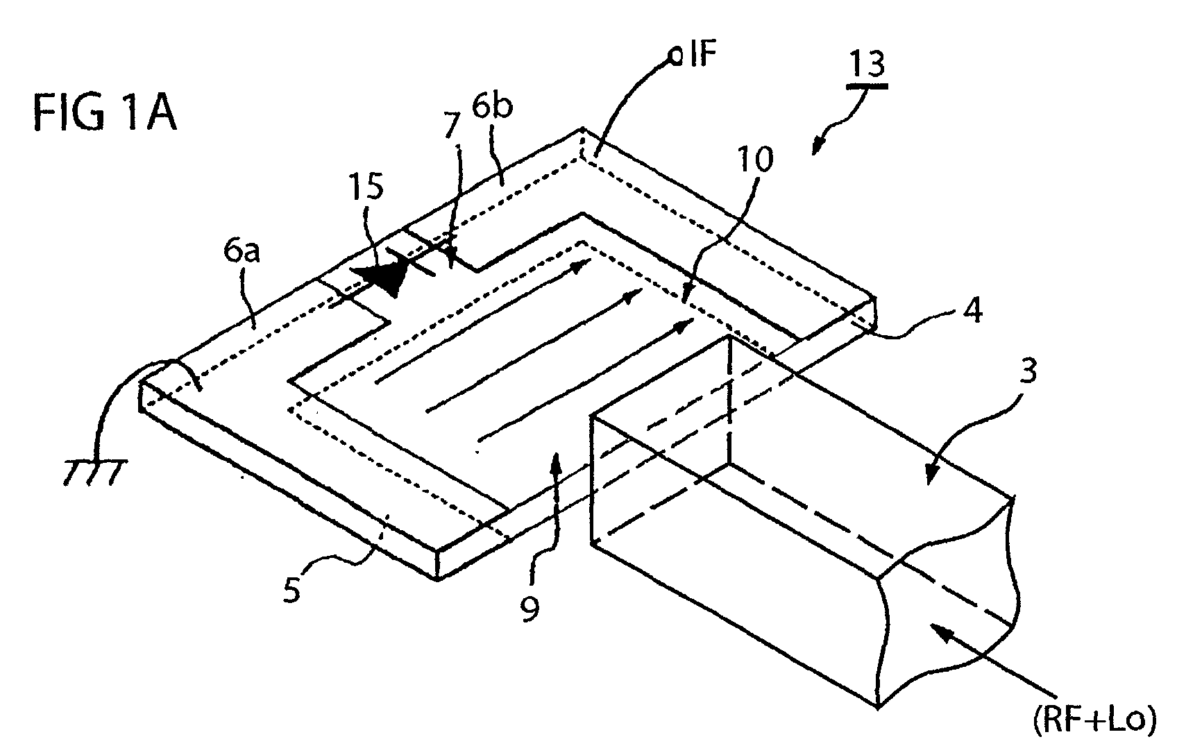
- Figs. 1A and 1B show a perspective view and a section illustrating the main part of a mixer according to a first embodiment of the present invention.
- Figs. 2A and 2B illustrate an example of electromagnetic field distributions in a rectangular planar TE-mode dielectric resonator.
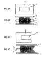
- Figs. 3A and 3B illustrate a plan view of a rectangular planar TE-mode dielectric resonator with both ends short-circuited and an example of magnetic distribution in the resonator
- Figs. 3C and 3D illustrate a plan view of a rectangular planar TE-mode dielectric resonator with one end short-circuited and an example of magnetic distribution in the resonator.
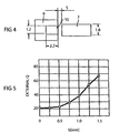
- Fig. 4 illustrates the positional relationship between the rectangular planar TE-mode dielectric resonator and a dielectric strip.
- Fig. 5 is a graph illustrating the correlation between an external Q and a space between the rectangular planar TE-mode dielectric resonator and the dielectric strip.
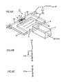
- Figs. 6A to 6C show a perspective view and circuit diagrams of the main part of a mixer according to a second embodiment of the present invention.
- Fig. 7 shows a perspective view of the main part of a mixer according to a third embodiment of the present invention.
- Fig. 8 shows a perspective view of the main part of a mixer according to a fourth embodiment of the present invention.
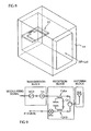
- Fig. 9 shows a block diagram of a radar module according to a fifth embodiment of the present invention.
- Fig. 10 shows a block diagram of a communication apparatus according to a sixth embodiment of the present invention.
- Figs. 1A and 1B show the structure of a mixer according a first embodiment of the present invention.
- Fig. 1A is a perspective view of the main part of the mixer when upper and lower conductive plates are removed.
- Fig. 1B is a section of the main part thereof.
- reference numeral 4 denotes a rectangular planar dielectric substrate.
- An electrode 5 is formed on the lower surface of the substrate 4 and electrodes 6a and 6b are formed on the upper surface thereof.
- the electrode 5 and the electrodes 6a and 6b are arranged such that electrode apertures 9 and 10 are opposed to each other via the dielectric substrate 4.
- the part of the dielectric substrate sandwiched between the mutually opposing electrode apertures 9 and 10 serves as a rectangular planar TE-mode dielectric resonator.
- a slit 7 continuous with the electrode aperture 10 is formed on the upper surface of the dielectric substrate 4.
- a mixer diode 15 such as a Schottky barrier diode is connected in a manner bridging the slit 7.
- reference numeral 3 denotes a dielectric strip.
- the dielectric strip 3 is arranged between conductive plates 1 and 2 shown in Fig. 1B to form a dielectric line (NRD guide) comprising the conductive plates 1 and 2 and the dielectric strip 3.
- the electrode 5 is formed on the lower main surface of the dielectric substrate 4 and the electrodes 6a and 6 b are formed on the upper main surface thereof.
- a circuit board 13 includes the dielectric substrate 4 having these electrodes formed thereon and the diode 15 mounted thereon.
- the circuit board 13 is arranged between the upper and lower conductive plates 1 and 2 making parallel conductive planes.
- the rectangular planar TE-mode dielectric resonator composed of the electrode apertures 9 and 10 is arranged near an end face of the dielectric strip 3.
- the LSM01-mode electric and magnetic fields of the dielectric line propagating through the dielectric strip 3 are coupled with the rectangular planar TE-mode dielectric resonator.
- a broken line indicates the distribution of the magnetic field and the symbol x indicates the distribution of the electric field.
- arrows shown in the rectangular planar TE-mode dielectric resonator indicate the electric field distribution of the TE-mode dielectric resonator.
- a (RF + Lo) voltage signal is induced between the electrodes 6a and 6b to be applied across the diode 15.
- an intermediate frequency (IF) signal is generated as a signal induced by the nonlinearity of the diode.
- the electrode 6a connected to the anode of the diode 15 is grounded, the IF signal can be obtained from the electrode 6b connected to the cathode thereof. In this manner, a single mixer can be formed.
- a circuit for supplying a bias voltage to the diode 15 and obtaining an IF signal is disposed on or outside the circuit board 13.
- Figs. 2A and 2B show electromagnetic distributions of the rectangular planar TE-mode dielectric resonator.
- Fig. 2A is a top view of the dielectric resonator when the conductive plates are removed and Fig. 2B is a section of the resonator taken along the line A-A' shown in Fig. 2A.
- Reference numerals shown in Figs. 2A and 2B correspond to the numerals shown in Figs. 1A and 1B.
- solid lines indicate electric flux lines and broken lines indicate magnetic flux lines to illustrate the distributions of electric and magnetic fields.
- the electrode aperture 10 is extended in a direction perpendicular to the direction of the electric field along a surface of the dielectric substrate to use the second harmonic (one wavelength) resonant mode of a TE10 mode, that is, a TE20 mode.
- planar TE-mode dielectric resonator has the following characteristics.
- the electrode apertures are rectangular-shaped so that the dielectric resonator serves as a rectangular planar TE-mode dielectric resonator, the formation of the electrode patterns can be facilitated. Furthermore, a dielectric resonator capable of having a high Q and suppressing the occurrence of a spurious mode is formed on the dielectric substrate having a limited area.
- the mixer of the invention can be made compact at low cost and can achieve loss reduction.
- Fig. 3A shows a plan view of a rectangular planar TE-mode dielectric resonator formed like the resonator shown in Figs. 2A and 2B
- Fig. 3B shows a magnetic field distribution thereof obtained by a finite-element method (FEM) analysis.
- Fig. 3C shows a plan view of a rectangular planar TE-mode dielectric resonator in which one end of the electrode aperture 10 is open-circuited
- Fig. 3D shows a magnetic field distribution obtained by the same method.
- Fig. 4 illustrates the dimensions of the dielectric resonator and the dielectric strip and the positional relationship between both of them.
- a unit of length is millimeters (mm).
- Fig. 5 is a graph showing changes in an external Q (Qe) obtained by the three dimensional FEM (HFSS) when the space S between the dielectric substrate and the dielectric strip shown in Fig. 4 is changed.
- the space S may be set to be 0.68 mm.
- the external Q remains a small value of approximately 20. That is, even though the relative positions between the dielectric substrate and the dielectric strip deviate to some extent, the dielectric resonator can be steadily and strongly coupled with the dielectric line.
- each of Figs. 6A to 6C illustrates a mixer according to a second embodiment of the invention.
- the structure of the mixer shown in Fig. 6A corresponds to the structure of the mixer shown in Fig. 1A.
- electrodes 5a and 5b are formed on the lower surface of a dielectric substrate 4 in a manner opposing electrodes 6a and 6b on the upper surface thereof.
- a diode 16 is connected in a part bridging a slit 8 between the electrodes 5a and 5b.
- the direction of the diode 16 is opposed to the direction of a diode 15 bridging a narrow slit 7 between the electrodes 6a and 6b on the upper surface of the dielectric substrate 4.
- the electrodes 5b and 6b are, for example, used for grounding or applying a bias voltage to obtain an IF signal from the electrodes 5a and 6a.
- the other parts in this embodiment are the same as those shown in the first embodiment.
- a bias voltage +B is applied to the electrode 5b via a filter comprising an inductor and a capacitor.
- Fig. 7 also shows a part corresponding to the part shown in Fig. 1A in the first embodiment.
- Each of the first and second embodiments uses the rectangular planar TE-mode dielectric resonator in which one end of each electrode is open-circuited and the open-circuited electrode portions of the dielectric resonator are positioned near the end of the dielectric strip 3.
- the embodiment shown in Fig. 7 uses the rectangular planar TE-mode dielectric resonator in which both ends of the electrodes are short-circuited, as shown in Figs. 3A and 3B.
- the mixer With the use of the resonator having the electrodes with both ends short-circuited, as compared with the resonator having the electrodes with one end open-circuited, a mixer having a higher unloaded Q and lower loss can be formed. However, since the strength of coupling between the dielectric resonator and the dielectric line reduces, the mixer has narrow band characteristics.
- the anode and cathode of the mixer diode can be isolated such that a direct current does not flow through the electrodes.
- the diode can be used under an optimum driving condition.
- the electrode on the lower surface of the dielectric substrate 4 may be arranged surface-symmetrically to the electrodes 6a, 6b, and 6c via the dielectric substrate 4. However, as shown in Fig. 7, the electrode 5 may have no electrode separating portions formed at positions opposing the electrode separating portions 11 and 12.
- each of the first to third embodiments uses the dielectric line as a signal-input line
- the mixer shown in Fig. 8 uses a waveguide as a signal-input line.
- reference numeral 14 denotes a rectangular waveguide.
- the circuit board 13 shown in one of Figs. 1, 6, and 7 is arranged inside the rectangular waveguide.
- the electromagnetic field of a TE10 mode wave propagating through the waveguide couples with the electromagnetic field of a rectangular planar TE-mode dielectric resonator formed on the circuit board 13.
- the mixer of the fourth embodiment is easily suitable to an apparatus using a waveguide as a transmission line.
- reference character VCO denotes a voltage-controlled oscillator using a Gunn diode and a varactor diode and reference character Iso. denotes an isolator for preventing a reflected signal from returning to the VCO.
- Reference character Cpl.a denotes a directional coupler comprising an NRD guide for obtaining some of the transmitted signals as local signals.
- Reference character Cir. denotes a circulator for sending a transmitted signal to a primary radiator of an antenna Ant. and sending a received signal to a mixer Mix.
- Reference character Cpl.b denotes a directional coupler comprising an NRD guide for mixing the received signal with the local signal and sending the mixed signals to the mixer Mix.. The mixer Mix.
- a signal processing circuit Based on the relationship between a modulating signal of the VCO and the IF signal, a signal processing circuit, which is not shown in the figure, detects the distance between the radar module and a target object and the relative velocity.
- the mixer Mix. shown in Fig. 9 is the mixer shown in one of the above embodiments.
- the radar module can have high efficiency and excellent detection capabilities.
- a received signal RF input from an antenna ANT is passed through a circulator to be amplified to a desired level by an RF amplifier. Unnecessary signals outside the amplified-signal receiving band are eliminated by a band pass filter RF-BPF.
- a target received signal is input to a reception mixer.
- a divider performs power-division of a desired frequency signal sent from a Lo oscillator at a dividing ratio necessary for transmission and reception.
- the Lo signal with a desired electric power is input to each of a transmission mixer and a reception mixer through two band pass filters Lo-BPF.
- the mixer according to one of the above embodiments is used. Since the transmission and reception mixers use both an RF terminal and a Lo terminal, the band pass filters RF-BPF serve to prevent the Lo signal from leaking to the antenna.
- IF signals equivalent to the difference between the RF signals and the Lo signals can be obtained from the reception mixer to which signals obtained by mixing the RF signals and the Lo signals are input.
- unnecessary signals are eliminated by the band pass filters IF-BPF, and only target IF signals are amplified to a desired level by an IF amplifier.
- IF input signals on the transmission side are passed through the IF-BPF to be input to the transmission mixer.
- the transmission mixer mixes Lo signals with the IF signals to generate RF signals.
- unnecessary signals are eliminated by the RF-BPF and only the desired signals are amplified to a desired electric power level by a power amplifier.
- the communication apparatus of the invention can be formed by adding necessary circuits such as a modulator and a demodulator to the transmission IF input section and the reception IF output section.
- the mixer has low conversion-loss characteristics. Accordingly, the communication apparatus incorporating the mixer can have high sensitivity.
- the upper and lower spaces sandwiched by the upper and lower conductive plates and the electrodes on the upper and lower surfaces of the dielectric substrate serve as blocking areas at a used frequency.
- energy entering the planar TE-mode dielectric resonator hardly leaks outside, there is no need for an RF trap circuit disposed in a conventional IF signal extraction circuit.
- the dielectric strip is arranged between the two conductive plates to form a dielectric line.
- necessary components are mounted on the dielectric substrate having electrode patterns formed by photolithography or the like to constitute a circuit board.
- the mixer of the invention can be formed only by arranging the dielectric line and the circuit board such that a desired strength of coupling can be obtained between the conductive plates of the dielectric line. Accordingly, the entire mixer can be easily manufactured.
- the low loss mixer is disposed in the circuit section for mixing a received signal and a local signal.
- the radar module of the invention can have high efficiency and an excellent detection capability.
- the communication apparatus of the invention can obtain high sensitivity.
Landscapes
- Physics & Mathematics (AREA)
- Electromagnetism (AREA)
- Engineering & Computer Science (AREA)
- Power Engineering (AREA)
- Waveguides (AREA)
- Radar Systems Or Details Thereof (AREA)
- Control Of Motors That Do Not Use Commutators (AREA)
Abstract
Description
Claims (9)
- A mixer comprising:a dielectric substrate (4) having first and second main surfaces;electrodes (5, 6) each having apertures (9, 10), the electrodes (5, 6) being provided on the first and second main surfaces of the dielectric substrate (4) such that the apertures (9, 10) are opposed to each other via the dielectric substrate (4);two conductive plates (1, 2) arranged substantially in parallel, the dielectric substrate (4) being disposed between the conductive plates (1, 2) to constitute a planar TE-mode dielectric resonator;a slit (7, 8) formed between the electrodes (5, 6) on a main surface of the substrate (4) so as to be continuous with one of the mutually opposing electrode apertures (9, 10); anda diode (15, 16) connected bridging the slit (7, 8).
- A single balanced mixer comprising:a dielectric substrate (4) having first and second main surfaces;electrodes (5, 6) having apertures (9, 10), the electrodes (5, 6) being provided on the first and second main surfaces of the dielectric substrate (4) such that the apertures (9, 10) are opposed to each other via the dielectric substrate (4);two conductive plates (1, 2) arranged substantially in parallel, the dielectric substrate (4) being disposed between the conductive plates (1, 2) to constitute a planar TE-mode dielectric resonator;slits (7, 8) formed on the first and second main surfaces of the dielectric substrate (4) and opposed to each other via the substrate (4) so as to be continuous with the respective electrode apertures (9, 10); anda diode (15m, 16) connected bridging each slit (7, 8).
- The mixer of claim 1, further comprising electrode separating portions (11, 12) provided to separate the electrodes (5, 6) to which both terminals of the diode (15, 16) are connected.
- The mixer of claim 2, further comprising electrode separating portions (11, 12) provided to separate the electrodes (5, 6) to which both terminals of at least one of the diodes (15, 16) are connected.
- The mixer of claim 3 or 4, wherein each of the electrode separating portions (11, 12) is provided at a position where the intensity of an electric field is high in the planar TE-mode dielectric resonator.
- The mixer of one of claims 1 to 5, wherein the electrode apertures (9, 10) are rectangular-shaped, and the dielectric resonator is a rectangular planar TE-mode dielectric resonator.
- The mixer of one of claims 1 to 6, further comprising a dielectric strip (3) arranged between the two conductive plates (1, 2) to form a dielectric line, the dielectric strip (3) being coupled with the dielectric resonator and being provided as a signal-input line.
- A radar module comprising the mixer of one of claims 1 to 7, the mixer being disposed in a circuit section mixing a received signal with a local signal.
- A communication apparatus comprising the mixer of one of claims 1 to 6, the mixer being disposed in a circuit section mixing one of a received signal and a transmitted signal with a local signal.
Applications Claiming Priority (2)
| Application Number | Priority Date | Filing Date | Title |
|---|---|---|---|
| JP2000350879A JP3765388B2 (en) | 2000-11-17 | 2000-11-17 | Mixer, radar device and communication device |
| JP2000350879 | 2000-11-17 |
Publications (3)
| Publication Number | Publication Date |
|---|---|
| EP1211803A2 true EP1211803A2 (en) | 2002-06-05 |
| EP1211803A3 EP1211803A3 (en) | 2003-09-17 |
| EP1211803B1 EP1211803B1 (en) | 2004-11-24 |
Family
ID=18824030
Family Applications (1)
| Application Number | Title | Priority Date | Filing Date |
|---|---|---|---|
| EP01126798A Expired - Lifetime EP1211803B1 (en) | 2000-11-17 | 2001-11-09 | Mixer using a Diode |
Country Status (5)
| Country | Link |
|---|---|
| US (1) | US6642882B2 (en) |
| EP (1) | EP1211803B1 (en) |
| JP (1) | JP3765388B2 (en) |
| KR (1) | KR100432793B1 (en) |
| DE (1) | DE60107366T2 (en) |
Families Citing this family (5)
| Publication number | Priority date | Publication date | Assignee | Title |
|---|---|---|---|---|
| US7206566B1 (en) * | 2004-07-21 | 2007-04-17 | Hrl Laboratories, Llc | Apparatus and method for frequency conversion |
| US7573420B2 (en) * | 2007-05-14 | 2009-08-11 | Infineon Technologies Ag | RF front-end for a radar system |
| HUE038112T2 (en) * | 2008-10-29 | 2018-09-28 | Grieshaber Vega Kg | High Frequency Module for Charging Level in W-band |
| JP2021015074A (en) * | 2019-07-13 | 2021-02-12 | マイクロメジャー株式会社 | Noncontact moisture meter and moisture content measurement method |
| DE102020112787A1 (en) | 2020-01-13 | 2021-07-29 | Infineon Technologies Ag | High frequency device with high frequency chip and waveguide structure |
Family Cites Families (16)
| Publication number | Priority date | Publication date | Assignee | Title |
|---|---|---|---|---|
| US4068232A (en) * | 1976-02-12 | 1978-01-10 | Fairchild Industries, Inc. | Passive encoding microwave transponder |
| JPS5298410A (en) * | 1976-02-16 | 1977-08-18 | Hitachi Ltd | Mixer circuit |
| US4215313A (en) * | 1979-05-31 | 1980-07-29 | Hughes Aircraft Company | Dielectric image guide integrated harmonic pumped mixer |
| US4461039A (en) * | 1982-09-20 | 1984-07-17 | Hughes Aircraft Company | Quasi-optical balanced biconical mixer |
| US4656478A (en) * | 1984-07-30 | 1987-04-07 | Asulab S.A. | Passive transponder for locating avalanche victims |
| DE3513059A1 (en) * | 1985-04-12 | 1986-10-23 | ANT Nachrichtentechnik GmbH, 7150 Backnang | Microwave mixer |
| JP2533800B2 (en) * | 1989-06-02 | 1996-09-11 | 山武ハネウエル株式会社 | Microwave response device |
| FR2652451A1 (en) * | 1989-09-26 | 1991-03-29 | Trt Telecom Radio Electr | Balanced HYPERFREQUENCY MIXER WITH "BALUN" CIRCUIT. |
| JPH03113387A (en) * | 1989-09-27 | 1991-05-14 | Nippon Soken Inc | Transponder for moving body identifying device |
| US5517195A (en) * | 1994-09-14 | 1996-05-14 | Sensormatic Electronics Corporation | Dual frequency EAS tag with deactivation coil |
| JP3045046B2 (en) * | 1995-07-05 | 2000-05-22 | 株式会社村田製作所 | Non-radiative dielectric line device |
| JP3106972B2 (en) | 1996-08-29 | 2000-11-06 | 株式会社村田製作所 | Diode mount structure, detector and mixer in dielectric line |
| JPH10341108A (en) * | 1997-04-10 | 1998-12-22 | Murata Mfg Co Ltd | Antenna system and radar module |
| JP3062593B2 (en) * | 1997-08-14 | 2000-07-10 | 北海道大学長 | Quasi-optical antenna / mixer element and array type quasi-optical antenna / mixer |
| JP2000151228A (en) * | 1998-11-09 | 2000-05-30 | Murata Mfg Co Ltd | Resonator device, oscillator, filter, duplexer and communication device |
| DE60021454T2 (en) * | 1999-02-09 | 2006-05-24 | Magnus Granhed | Encapsulated antenna in passive transponder |
-
2000
- 2000-11-17 JP JP2000350879A patent/JP3765388B2/en not_active Expired - Fee Related
-
2001
- 2001-11-02 US US10/003,648 patent/US6642882B2/en not_active Expired - Fee Related
- 2001-11-09 EP EP01126798A patent/EP1211803B1/en not_active Expired - Lifetime
- 2001-11-09 DE DE60107366T patent/DE60107366T2/en not_active Expired - Lifetime
- 2001-11-15 KR KR10-2001-0071071A patent/KR100432793B1/en not_active Expired - Fee Related
Also Published As
| Publication number | Publication date |
|---|---|
| US6642882B2 (en) | 2003-11-04 |
| JP2002158540A (en) | 2002-05-31 |
| KR20020038521A (en) | 2002-05-23 |
| KR100432793B1 (en) | 2004-05-24 |
| US20020084932A1 (en) | 2002-07-04 |
| DE60107366T2 (en) | 2005-12-01 |
| JP3765388B2 (en) | 2006-04-12 |
| EP1211803A3 (en) | 2003-09-17 |
| DE60107366D1 (en) | 2004-12-30 |
| EP1211803B1 (en) | 2004-11-24 |
Similar Documents
| Publication | Publication Date | Title |
|---|---|---|
| Yabuki et al. | Stripline dual-mode ring resonators and their application to microwave devices | |
| JP3268807B2 (en) | Radio frequency mixer circuit | |
| US6614332B2 (en) | Transmission line, integrated circuit, and transmitter receiver | |
| US7973615B2 (en) | RF module | |
| EP0091042B1 (en) | Millimeter-wave mixer | |
| EP0827270A1 (en) | Diode mount structure in dielectric waveguide device, and detector and mixer using the diode mount structure | |
| US6597260B2 (en) | Filter, multiplexer, and communication apparatus | |
| EP1211803B1 (en) | Mixer using a Diode | |
| US20040041668A1 (en) | High-frequency circuit device and transmitter/receiver | |
| US6931246B2 (en) | Line coupling structure, mixer, and receiving/transmitting apparatus comprised of suspended line and dielectric waveguide | |
| US6535089B1 (en) | High-frequency circuit device and communication apparatus using the same | |
| US7408430B2 (en) | High-frequency circuit device and transmitting and receiving apparatus | |
| US6232854B1 (en) | Dielectric resonator device, dielectric filter, oscillator, sharing device, and electronic apparatus | |
| US6344779B1 (en) | Oscillator and radio equipment | |
| JP3405229B2 (en) | Dielectric line device and transmission device | |
| EP0971477A1 (en) | Frequency multiplier, dielectric transmission line device, and radio device | |
| Chang | Millimeter-wave planar integrated circuits and subsystems | |
| EP1093218B1 (en) | Oscillator and radio equipment | |
| EP0906658B1 (en) | Subharmonic frequency converter for applications to millimetric radio waves | |
| JPH10224257A (en) | Transmitter-receiver | |
| KR100330773B1 (en) | Receiver using Multi-Layer Non-radiative Dielectric Waveguide | |
| KR100256951B1 (en) | Symmetrical Planar Single-sided Microwave Mix-Modulator | |
| JP2000216604A (en) | Transmission line converter, oscillator and communication unit | |
| Begemann et al. | A Ku-band fin-line front-end with a hybrid-coupled balanced mixer and a Gunn oscillator | |
| KR20020062607A (en) | Wideband Mixer for NRD Waveguide Circuit |
Legal Events
| Date | Code | Title | Description |
|---|---|---|---|
| PUAI | Public reference made under article 153(3) epc to a published international application that has entered the european phase |
Free format text: ORIGINAL CODE: 0009012 |
|
| 17P | Request for examination filed |
Effective date: 20011109 |
|
| AK | Designated contracting states |
Kind code of ref document: A2 Designated state(s): AT BE CH CY DE DK ES FI FR GB GR IE IT LI LU MC NL PT SE TR |
|
| AX | Request for extension of the european patent |
Free format text: AL;LT;LV;MK;RO;SI |
|
| PUAL | Search report despatched |
Free format text: ORIGINAL CODE: 0009013 |
|
| AK | Designated contracting states |
Kind code of ref document: A3 Designated state(s): AT BE CH CY DE DK ES FI FR GB GR IE IT LI LU MC NL PT SE TR |
|
| AX | Request for extension of the european patent |
Extension state: AL LT LV MK RO SI |
|
| RIC1 | Information provided on ipc code assigned before grant |
Ipc: 7H 03D 1/10 B Ipc: 7H 03D 9/06 A |
|
| GRAP | Despatch of communication of intention to grant a patent |
Free format text: ORIGINAL CODE: EPIDOSNIGR1 |
|
| AKX | Designation fees paid |
Designated state(s): DE FR GB |
|
| GRAS | Grant fee paid |
Free format text: ORIGINAL CODE: EPIDOSNIGR3 |
|
| GRAA | (expected) grant |
Free format text: ORIGINAL CODE: 0009210 |
|
| AK | Designated contracting states |
Kind code of ref document: B1 Designated state(s): DE FR GB |
|
| REG | Reference to a national code |
Ref country code: GB Ref legal event code: FG4D |
|
| REF | Corresponds to: |
Ref document number: 60107366 Country of ref document: DE Date of ref document: 20041230 Kind code of ref document: P |
|
| REG | Reference to a national code |
Ref country code: IE Ref legal event code: FG4D |
|
| PLBE | No opposition filed within time limit |
Free format text: ORIGINAL CODE: 0009261 |
|
| STAA | Information on the status of an ep patent application or granted ep patent |
Free format text: STATUS: NO OPPOSITION FILED WITHIN TIME LIMIT |
|
| 26N | No opposition filed |
Effective date: 20050825 |
|
| ET | Fr: translation filed | ||
| PGFP | Annual fee paid to national office [announced via postgrant information from national office to epo] |
Ref country code: FR Payment date: 20101123 Year of fee payment: 10 |
|
| PGFP | Annual fee paid to national office [announced via postgrant information from national office to epo] |
Ref country code: DE Payment date: 20101104 Year of fee payment: 10 |
|
| PGFP | Annual fee paid to national office [announced via postgrant information from national office to epo] |
Ref country code: GB Payment date: 20101103 Year of fee payment: 10 |
|
| GBPC | Gb: european patent ceased through non-payment of renewal fee |
Effective date: 20111109 |
|
| REG | Reference to a national code |
Ref country code: FR Ref legal event code: ST Effective date: 20120731 |
|
| REG | Reference to a national code |
Ref country code: DE Ref legal event code: R119 Ref document number: 60107366 Country of ref document: DE Effective date: 20120601 |
|
| PG25 | Lapsed in a contracting state [announced via postgrant information from national office to epo] |
Ref country code: GB Free format text: LAPSE BECAUSE OF NON-PAYMENT OF DUE FEES Effective date: 20111109 |
|
| PG25 | Lapsed in a contracting state [announced via postgrant information from national office to epo] |
Ref country code: FR Free format text: LAPSE BECAUSE OF NON-PAYMENT OF DUE FEES Effective date: 20111130 |
|
| PG25 | Lapsed in a contracting state [announced via postgrant information from national office to epo] |
Ref country code: DE Free format text: LAPSE BECAUSE OF NON-PAYMENT OF DUE FEES Effective date: 20120601 |