EP1211773A1 - Support pour appareillage, en particulier pour appareillage électrique, à rapporter sur le socle d'une goulotte - Google Patents
Support pour appareillage, en particulier pour appareillage électrique, à rapporter sur le socle d'une goulotte Download PDFInfo
- Publication number
- EP1211773A1 EP1211773A1 EP01402926A EP01402926A EP1211773A1 EP 1211773 A1 EP1211773 A1 EP 1211773A1 EP 01402926 A EP01402926 A EP 01402926A EP 01402926 A EP01402926 A EP 01402926A EP 1211773 A1 EP1211773 A1 EP 1211773A1
- Authority
- EP
- European Patent Office
- Prior art keywords
- base
- support according
- crosspiece
- chute
- support
- Prior art date
- Legal status (The legal status is an assumption and is not a legal conclusion. Google has not performed a legal analysis and makes no representation as to the accuracy of the status listed.)
- Granted
Links
- 239000011324 bead Substances 0.000 claims description 5
- 230000000295 complement effect Effects 0.000 claims description 5
- 238000000926 separation method Methods 0.000 claims description 5
- 230000015572 biosynthetic process Effects 0.000 claims description 4
- 238000006073 displacement reaction Methods 0.000 claims 1
- 230000037431 insertion Effects 0.000 abstract 1
- 238000003780 insertion Methods 0.000 abstract 1
- 239000007787 solid Substances 0.000 abstract 1
- 238000009434 installation Methods 0.000 description 7
- 238000004519 manufacturing process Methods 0.000 description 4
- 239000004020 conductor Substances 0.000 description 3
- 244000245420 ail Species 0.000 description 2
- 239000000463 material Substances 0.000 description 2
- 238000000465 moulding Methods 0.000 description 2
- 229910052754 neon Inorganic materials 0.000 description 2
- GKAOGPIIYCISHV-UHFFFAOYSA-N neon atom Chemical compound [Ne] GKAOGPIIYCISHV-UHFFFAOYSA-N 0.000 description 2
- 125000006850 spacer group Chemical group 0.000 description 2
- 239000000470 constituent Substances 0.000 description 1
Images


Classifications
-
- H—ELECTRICITY
- H02—GENERATION; CONVERSION OR DISTRIBUTION OF ELECTRIC POWER
- H02G—INSTALLATION OF ELECTRIC CABLES OR LINES, OR OF COMBINED OPTICAL AND ELECTRIC CABLES OR LINES
- H02G3/00—Installations of electric cables or lines or protective tubing therefor in or on buildings, equivalent structures or vehicles
- H02G3/02—Details
- H02G3/08—Distribution boxes; Connection or junction boxes
- H02G3/12—Distribution boxes; Connection or junction boxes for flush mounting
- H02G3/128—Distribution boxes; Connection or junction boxes for flush mounting in plinths, channels, raceways or similar
Definitions
- the present invention relates generally to the chutes of the type of those implemented, for example, for support, housing and protection of various devices, and in particular of various devices electrical, as well as for the support, housing and protection of conductors or pipes necessary to serve these equipment.
- the invention relates more particularly to a support for apparatus, in particular for electrical equipment, to be transferred transversely to the base of a return channel directed towards each other, comprising at least one crosspiece, extending in a general direction X, which comprises, on two opposite end edges, engagement means adapted to engage with said returns.
- each crosspiece of the apparatus support comprises, on its two edges end, groove means in which are engaged the returns of lateral wings of the base of the chute.
- the support for apparatus is fixed on the returns of the wings of the base of the chute using the legs which come fit into particular arrangements of said wing returns.
- the locking of the support for equipment on the base of the chute is made using screws which press a fixing plate on the rear face of said returns.
- the main disadvantage of the aforementioned supports is that they require, for their installation on the base of a chute, the spacing of the wing returns. This installation maneuver is delicate especially in the case for example chutes installed at an angle, and does not allow the said support to be placed blind, when for example this one is equipped with a wall lamp which rests on a section of cover closing the base of the chute.
- the invention proposes a support for apparatus as defined in the introduction, in which said engagement means comprise, on at least one of said end edges, at least one latching tooth secured to said crosspiece via an elastic link which allows a slight movement in translation back and forth of said latching tooth in said general direction X of the crosspiece between a first projecting position and a second recessed position relative to said first position.
- such a support for apparatus can be easily placed on the base of a chute, by simple fitting, without requiring the prior separation of the lateral wings from the base of the chute.
- each latching tooth coming into contact with a wing return from the base of the chute, clears by moving slightly in translation from its first protruding position to its second recessed position, then returns elastically in its first projecting position by positioning itself under said return, in support against it.
- each latching tooth comprises a bearing surface and a chamfered surface which is continuously connected to said bearing surface, said chamfered surface forming a suitable engagement surface, during the placing said support on the base of the chute, to be erased automatically under one of said returns from said base so that said surface in support comes to bear against it.
- each latching tooth facilitates installation blind of the support for apparatus according to the invention on the base of a chute.
- such an apparatus support allows installation in applied to the closing cover of the trunking of an apparatus, by example a lighting apparatus, which, in particular, has a width more narrower than the width of the opening of the base of the chute.
- the cover or the cover section concerned is provided of holes for the passage of cable or supply conductors lighting equipment, as well as for the passage of means of fixing of said apparatus, for example screws, for fixing the apparatus according to the invention on the support.
- the apparatus support in accordance with the invention is then placed in place on the underside of said cover and is held by a light jamming between the latter's snap ribs.
- the switchgear having been fixed to the switchgear support and wired, the installation of the assembly on the base of the chute can then be carried out blind, said support for apparatus coming from, via its latching teeth, engaged with the returns of the lateral wings of the base of the chute (as mentioned above), when the cover is snapped onto said base.
- the apparatus 50 is an apparatus lighting with neon tube which is fixed on the wall on the closing cover 16 of the base 11 of the chute 10.
- the base 11 of the chute 10 has, overall, in section transverse, a V-shaped profile, and forms, longitudinally, by itself, only one single compartment.
- the longitudinal walls 13 between which the apparatus must be mounted lighting 50 therefore in this case form the outer lateral wings of the base 11 of chute 10.
- these lateral wings 13 have, both of them, along their free edge, a return 14 which, substantially parallel to the sole 12, is directed inward, and which, for the snap-fastening of a cover 16, forms a bead generally shaped into a groove.
- the lateral wings 13 of the base 11 of the chute 10 have returns 14 directed towards each other.
- the lateral wings 13 of the base 11 of the chute 10 comprise, here, also, along their free edge, an edge 15 falling towards the outside of the chute 10.
- the internal face of the lateral wings 13 of the base 11 of the chute 10, as well as the inner face of the sole 12 are provided with ribs longitudinal 13A, 12A.
- the closing cover 16 of the base 11 of the chute 10, plus particularly shown in Figures 5 and 7, has tabs longitudinal 17 provided at their free end with beads 17A for latching in the grooves formed by the returns 14 of the side wings 13 of the base 11 of the chute 10.
- This cover 16 comprises, between the two legs latching 17, a shutter portion 16A and, on its longitudinal sides, the outside of each of the latching tabs 17, drooping edges 18 intended to cover the drooping edges 15 of the base 11 of the chute 10.
- the chute 10 equipped with its cover 16 is well known in itself and does not will therefore not be described in more detail here.
- a support for apparatus in particular an electrical apparatus, allowing here to place an apparatus lighting 50 with neon tube applied to the cover 16.
- This support for apparatus includes at least one cross 20 extending in a general direction X capable of being reported transversely on the base 11 of the chute 10 between the two returns 14 directed towards each other.
- the switchgear support has two identical crosspieces 20 spaced apart on the other for mounting the relatively long lighting apparatus 50.
- each of the crosspieces 20 is placed near one end of said lighting equipment 50.
- Each cross member 20 comprises, in a central part, three openings parallel longitudinal feedthroughs 29 forming mounting stud grooves 40 for fixing the apparatus 50 by screws to the apparatus support.
- this pad 40 comprises, on a base 41, a central protuberance 42 provided with a threaded orifice 43 intended to accommodate, for example, a screw fixing of the apparatus 50 on the support for apparatus and, on both sides of this central protuberance 42, mounting wings 44 provided on their external face of notches 44A.
- the central protuberance 42 of the pad 40 is introduced by the rear face 20B of the cross member 20 in the central opening 29 so that the threaded orifice 43 emerges on the front face 20A of the cross-member 20 so as to be accessible from the outside.
- the mounting wings 44 engage in the two openings 29 positioned on either side of said opening central 29 and engage, by their notches 44A, with notches 29A of complementary shape provided on one of the side walls of said openings 29 for fixing the stud 40 on the crosspiece 20 (see FIG. 3).
- This notch cooperation makes it possible to position the pad 40 in different positions along the cross 20.
- each cross member 20 comprises, on two end edges 21 opposite, engagement means 22, 23 capable of engaging with said returns 14 from the base 11 of the chute 10.
- These engagement means include groove means provided recessed on the corresponding edge of the crosspiece.
- each cross 20 forms, on each of its edges opposite transverse, and along them, for the definition of corresponding groove means, in this case a groove, a lip 22 located on the side of the front face 20A of the cross-member 20.
- each lip 22 comes in press on the corresponding return 14 of said base 11.
- each cross member 20 include, here, on each of said opposite end edges 21, a latching tooth 23 secured to said cross member 20 by means of an elastic connection 24 which allows a slight translational movement back and forth of said latching tooth 23 in said general direction X of the crosspiece 20 between a first position in projection (see Figure 2) and a second position recessed with respect to said first position.
- the two snap-fit teeth 23 form two separate parts, reported by their elastic link 24 associated with said cross member 20.
- Each snap-fit tooth 23 has a bearing surface 23A oriented on the side of the front face 20A of the cross member 20 and a surface chamfered 23B, turned on the side of the rear face 20B of the crosspiece 20, which continuously connects to said support surface 23A.
- the chamfered surface 23B of each snap-fit tooth 23 forms a suitable engagement surface, when the installation of the support for equipment on the base 11 of the chute 10, automatically erase under one of said returns 14 from the base 11 of the chute 10 so that the bearing surface 23A of the latching tooth 23 comes to bear against it (see Figures 6 and 7).
- connection elastic of each latching tooth here comprises two elastic tabs corrugated 24 parallel which come from formation with said latching tooth 23 and which each have, at a free end, fixing means 25 to cross 20.
- said fixing means are latching means which comprise, at the end of each of the corrugated elastic tabs 24, a bead 25 cooperating elastically with a stud 30 carried by the rear face 20B of cross member 20.
- Each snap-fit tooth 23 is fixed to the rear face 20B of the cross 20, so that, in its first projecting position, it completes the groove formed on each of the transverse sections of said cross constituting on the side of the rear face 20B the pendant of the lips 22 located on the side of the front face 20A of the cross member.
- each cross member 20 comprises, on its rear face 20B facing inward of the base 11 of the chute 10, on either side of each snap-fit tooth 23, two guides 27 for translational guiding of said snap-fit tooth 23.
- each slide is formed by a stud 27 extending along the axis X of the cross member 20 and having a guide surface placed opposite the rear face 20B of the cross member 20, on which is intended to slide a complementary guide surface 26A provided on each of the snap-fit teeth 23.
- Each complementary guide surface 26A is formed by the face lower of a stud 26 provided on each lateral side of each tooth latching 23.
- the studs 26 form the junction between the bearing surfaces 23A and chamfered 23B, and the corrugated elastic tabs 24.
- the slides 27 provided on each of the crosspieces 20 extend over a length such that the mechanical resistance of the assembly formed by the cross member and the snap teeth is satisfactory. This resistance mechanical is all the more satisfactory as the play existing between the slides and the sleepers is very small.
- each of the slides 27 of each cross member 20 is carried by a tab 28 which generally extends perpendicular to the plane of the rear face 20B of said cross member 20 and which has a substantially pointed profile with a base secured to the face rear 20B wider than its free end, so that each of the legs 28 includes an outer edge 28A extending slightly obliquely by relative to the general direction of the tab 28.
- This external section 28A forms, during the establishment of said support on the base 11 of the chute 10, a bearing surface on one of said returns 14 from the base 11 capable of causing automatically a slight separation of the lateral wings 13 of said base 11, if these lateral wings are too close together at the end of production of said base 11.
- Each cross member 20 here has four tabs 28 positioned substantially at the four corners of the crosspiece 20.
- the two latching teeth 23 of each cross member 20 and their associated elastic connection 24, each comprising two wavy elastic tabs 24 constitute a single piece attached to said cross member 20, on its rear face 20B, by a rigid central part 25 provided a central hole 25A, this central part forming a connection part between said elastic connections 24.
- Such an embodiment however requires a set of teeth latching and associated elastic connections by width of trough base, unlike the embodiment of Figures 1 to 3 and 5 to 7, according to which the snap-fit teeth are attached to the ends of each cross member 20 of the support for equipment.
- each cross member 20 of the apparatus support here comprises a spacer 60 connected to the cross-member by a cut-out link 61.
- This spacer 60 allows to adapt the crosspiece to different cover heights, for example a cover extending between the wing returns, touching the cross member and a cover covering the wing returns, as is the case of the cover 16 of FIG. 5.
- Each cross member 20 is made in one piece by molding a plastic material.
- Each snap-fit tooth 23 of the first embodiment shown in Figures 1 to 3 and 5 to 7 is also made in one piece by molding of a plastic material.
- the apparatus support described above can be easily mount on the base of the chute and allows in particular to fix on this base a lighting apparatus 50 of the wall-mounted type, as represented by example in FIG. 5, which, due in part to its small width relative to that of the opening of the base 11 of the chute 10, is mounted on the cover 16 of the chute 10.
- the cover 16 is provided with holes made for the passage of the cable or the power supply conductors, as well as for the passage of means for fixing the lighting equipment 50 to the support for switchgear, here fixing screws intended to engage in the tapped holes 43 of the pads 40 of the crosspieces 20.
- the crosspieces 20 are then placed on the internal face of the closing part 16A of the cover 16 and held by a slight wedging between the latching tabs 17 of the cover 16, and in particular of its lips 22.
- the lighting equipment 50 having been wired and fixed to the cover 16 by through the crosspieces 20, the assembly of the assembly is carried out blind on the base 11 of the chute 10, that is to say that the crosspieces are engaged on the returns 14 of the base 11 during the fitting of the cover 16 thereon.
- the snap teeth slide in the runners 27 provided on the rear face 20B of the crosspieces 20, over a length such that the mechanical strength of the assembly is entirely satisfactory.
- crossbars 20 (as shown more particularly Figures 6 and 7) are supported, on the one hand, on the returns 14 of the base of the chute by the lips 22, and, on the other hand, under the returns 14 of the chute base by snap-in teeth 23.
- the apparatus support is in the form of a frame, each of the opposite longitudinal edges carrying more than one latching tab elastic.
Landscapes
- Engineering & Computer Science (AREA)
- Architecture (AREA)
- Civil Engineering (AREA)
- Structural Engineering (AREA)
- Mutual Connection Of Rods And Tubes (AREA)
- Supports For Pipes And Cables (AREA)
- Connection Of Plates (AREA)
- Clamps And Clips (AREA)
- Mounting Components In General For Electric Apparatus (AREA)
Abstract
Description
- chaque traverse comprend, sur une face arrière tournée vers l'intérieur du socle de la goulotte, de part et d'autre de chaque dent d'encliquetage, deux glissières de guidage à translation de ladite dent d'encliquetage ;
- chaque glissière est formée par un plot s'étendant selon l'axe X de la traverse et présentant une surface externe de guidage sur laquelle est destinée à glisser une surface de guidage complémentaire prévue sur un côté latéral de ladite dent d'encliquetage ;
- chacune desdites glissières est portée par une patte qui s'étend généralement perpendiculairement au plan de la face arrière de ladite traverse et qui présente un profil sensiblement en pointe avec une base solidaire de ladite face arrière plus large que son extrémité libre, de sorte que ladite patte comprend une tranche externe s'étendant légèrement en oblique par rapport à la direction générale de ladite patte, cette tranche externe formant, lors de la mise en place dudit support sur le socle de la goulotte, une surface d'appui sur un desdits retours dudit socle apte à provoquer automatiquement un léger écartement des ailes latérales dudit socle, si ces ailes latérales sont trop rapprochées en sortie de production du socle ;
- ladite liaison élastique comprend au moins une patte élastique ondulée qui vient de formation avec ladite dent d'encliquetage et qui présente à une extrémité des moyens de fixation à ladite traverse ;
- lesdits moyens de fixation sont des moyens d'encliquetage ;
- lesdits moyens d'encliquetage comprennent, à l'extrémité de ladite patte élastique ondulée, un bourrelet coopérant élastiquement avec un plot porté par la face arrière de la traverse ;
- chaque dent d'encliquetage comprend deux pattes élastiques ondulées parallèles formant ladite liaison élastique ;
- lesdits moyens d'engagement comprennent, sur chacun desdits bords d'extrémité de ladite traverse, une dent d'encliquetage ;
- les deux dents d'encliquetage forment deux pièces distinctes rapportées par leur liaison élastique associée à ladite traverse ;
- les deux dents d'encliquetage et leur liaison élastique associée constituent une pièce unique fixée à ladite traverse par une partie centrale rigide formant partie de raccordement entre lesdites liaisons élastiques ; et
- le support pour appareillage se présente sous la forme d'un cadre avec deux parties longitudinales parallèles reliant deux traverses d'extrémité équipées, sur leurs bords d'extrémité opposés, des dents d'encliquetage à liaison élastique.
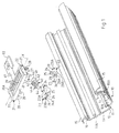
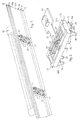
- la figure 1 est une vue en perspective éclatée du support pour appareillage selon l'invention à mettre en place sur un socle de goulotte ;
- la figure 2 est une vue en perspective de dessus du support pour appareillage de la figure 1 ;
- la figure 3 est une vue en perspective de dessous du support pour appareillage de la figure 2 ;
- la figure 4 est une vue en perspective de dessous d'une variante de réalisation du support pour appareillage de la figure 3 ;
- la figure 5 est une vue en perspective de dessous du couvercle de fermeture de la goulotte représentée sur la figure 1, sur lequel est posé en applique un appareillage d'éclairage fixé au support pour appareillage selon l'invention ;
- la figure 6 est une vue en coupe du support pour appareillage monté dans la goulotte de la figure 1 ; et
- la figure 7 est une vue de côté de la goulotte de la figure 1 fermée par son couvercle muni en applique d'un appareillage d'éclairage fixé au support pour appareillage selon l'invention.
Claims (13)
- Support pour appareillage, en particulier pour appareillage électrique, à rapporter transversalement sur le socle (11) d'une goulotte (10) à retours (14) dirigés l'un vers l'autre, comportant au moins une traverse (20), s'étendant selon une direction générale X, qui comporte, sur deux bords d'extrémité (21) opposés, des moyens d'engagement (22, 23) aptes à venir en prise avec lesdits retours (14), caractérisé en ce que lesdits moyens d'engagement comprennent, sur au moins un desdits bords d'extrémité (21), au moins une dent d'encliquetage (23) solidarisée à ladite traverse (20) par l'intermédiaire d'une liaison élastique (24) qui autorise un léger déplacement en translation d'aller-retour de ladite dent d'encliquetage (23) selon ladite direction générale X entre une première position en saillie et une seconde position en retrait par rapport à ladite première position.
- Support pour appareillage selon la revendication 1, caractérisé en ce que chaque dent d'encliquetage (23) comprend une surface d'appui (23A) et une surface chanfreinée (23B) qui se raccorde continûment à ladite surface d'appui (23A), ladite surface chanfreinée (23B) formant une surface d'engagement apte, lors de la mise en place dudit support sur le socle (11) de la goulotte (10), à s'effacer automatiquement sous un desdits retours (14) dudit socle (11) pour que ladite surface d'appui (23A) vienne en appui contre celui-ci.
- Support pour appareillage selon l'une des revendications 1 ou 2, caractérisé en ce que chaque traverse (20) comprend, sur une face arrière (20B) tournée vers l'intérieur du socle (11) de la goulotte (10), de part et d'autre de chaque dent d'encliquetage (23), deux glissières (27) de guidage à translation de ladite dent d'encliquetage (23).
- Support pour appareillage selon la revendication 3, caractérisé en ce que chaque glissière est formée par un plot (27) s'étendant selon l'axe X de la traverse (20) et présentant une surface externe de guidage sur laquelle est destinée à glisser une surface de guidage complémentaire (26A) prévue sur un côté latéral de ladite dent d'encliquetage (23).
- Support pour appareillage selon l'une des revendications 3 ou 4, caractérisé en ce que chacune desdites glissières (27) est portée par une patte (28) qui s'étend généralement perpendiculairement au plan de la face arrière (20B) de ladite traverse (20) et qui présente un profil sensiblement en pointe avec une base solidaire de ladite face arrière (20B) plus large que son extrémité libre, de sorte que ladite patte (28) comprend une tranche externe (28A) s'étendant légèrement en oblique par rapport à la direction générale de ladite patte (28), cette tranche externe (28A) formant, lors de la mise en place dudit support sur le socle (11) de la goulotte (10), une surface d'appui sur un desdits retours (14) dudit socle apte à provoquer automatiquement un léger écartement des ailes latérales (13) dudit socle (11).
- Support pour appareillage selon l'une des revendications précédentes, caractérisé en ce que ladite liaison élastique comprend au moins une patte élastique ondulée (24) qui vient de formation avec ladite dent d'encliquetage (23) et qui présente à une extrémité des moyens de fixation (25) à ladite traverse (20).
- Support pour appareillage selon la revendication 6, caractérisé en ce que lesdits moyens de fixation sont des moyens d'encliquetage.
- Support pour appareillage selon la revendication 7, caractérisé en ce que lesdits moyens d'encliquetage comprennent, à l'extrémité de ladite patte élastique ondulée (24), un bourrelet (25) coopérant élastiquement avec un plot (30) porté par la face arrière (20B) de la traverse (20).
- Support pour appareillage selon l'une des revendications 6 à 8, caractérisé en ce que chaque dent d'encliquetage (23) comprend deux pattes élastiques ondulées (24) parallèles formant ladite liaison élastique.
- Support pour appareillage selon l'une des revendications précédentes, caractérisé en ce que lesdits moyens d'engagement comprennent, sur chacun desdits bords d'extrémité (21) de ladite traverse, une dent d'encliquetage (23).
- Support pour appareillage selon la revendication 10, caractérisé en ce que les deux dents d'encliquetage (23) forment deux pièces distinctes rapportées par leur liaison élastique (24) associée à ladite traverse (20).
- Support pour appareillage selon la revendication 10, caractérisé en ce que les deux dents d'encliquetage (23) et leur liaison élastique (24) associée constituent une pièce unique fixée à ladite traverse (20) par une partie centrale rigide (25) formant partie de raccordement entre lesdites liaisons élastiques (24).
- Support pour appareillage selon l'une des revendications 1 à 12, caractérisé en ce qu'il se présente sous la forme d'un cadre avec deux parties longitudinales parallèles reliant deux traverses d'extrémité équipées, sur leurs bords d'extrémité opposés, des dents d'encliquetage à liaison élastique.
Applications Claiming Priority (2)
| Application Number | Priority Date | Filing Date | Title |
|---|---|---|---|
| FR0015423A FR2817402B1 (fr) | 2000-11-29 | 2000-11-29 | Support pour appareillage, en particulier pour appareillage electrique, pour goulotte |
| FR0015423 | 2000-11-29 |
Publications (2)
| Publication Number | Publication Date |
|---|---|
| EP1211773A1 true EP1211773A1 (fr) | 2002-06-05 |
| EP1211773B1 EP1211773B1 (fr) | 2011-05-18 |
Family
ID=8857012
Family Applications (1)
| Application Number | Title | Priority Date | Filing Date |
|---|---|---|---|
| EP01402926A Expired - Lifetime EP1211773B1 (fr) | 2000-11-29 | 2001-11-14 | Support pour appareillage, en particulier pour appareillage électrique, à rapporter sur le socle d'une goulotte |
Country Status (7)
| Country | Link |
|---|---|
| EP (1) | EP1211773B1 (fr) |
| BR (1) | BR0106053A (fr) |
| ES (1) | ES2365385T3 (fr) |
| FR (1) | FR2817402B1 (fr) |
| HU (1) | HUP0105187A2 (fr) |
| PL (1) | PL350842A1 (fr) |
| RU (1) | RU2273083C2 (fr) |
Cited By (1)
| Publication number | Priority date | Publication date | Assignee | Title |
|---|---|---|---|---|
| ES2222820A1 (es) * | 2003-07-25 | 2005-02-01 | Aem, S.A | Dispositivo de soporte para al menos un aparato electrico. |
Families Citing this family (2)
| Publication number | Priority date | Publication date | Assignee | Title |
|---|---|---|---|---|
| FR2912003B1 (fr) * | 2007-01-31 | 2009-04-17 | Icm Group | Dispositif de fixation pour chemin de cables en fils |
| FR2916912B1 (fr) * | 2007-06-04 | 2009-08-21 | Inovac Soc Par Actions Simplif | Accessoire pour goulotte electrique |
Citations (2)
| Publication number | Priority date | Publication date | Assignee | Title |
|---|---|---|---|---|
| EP0862253A1 (fr) * | 1997-03-01 | 1998-09-02 | Hermann Kleinhuis GmbH. & Co. KG | Canalisation pour câbles, tel que canalisation pour installation électrique ou montage d'appareils |
| DE29909946U1 (de) * | 1999-06-08 | 2000-10-19 | Tehalit GmbH, 67716 Heltersberg | Leitungsführungskanal für den frontseitigen Einbau von Elektroinstallationsgeräten |
Family Cites Families (4)
| Publication number | Priority date | Publication date | Assignee | Title |
|---|---|---|---|---|
| DK128709B (da) * | 1971-10-25 | 1974-06-17 | Nordiske Kabel Og Traadfab As | Tilkoblingsanordning for tilkobling af et med et elektrisk organ forsynet isolationshus til en installationsliste. |
| DE4110690A1 (de) * | 1991-04-03 | 1992-10-08 | Kleinhuis Hermann Gmbh | Kabelkanal, wie bruestungskanal |
| SE9403693D0 (sv) * | 1994-04-18 | 1994-10-28 | Lars Eric Maansson | Kanallist |
| FR2741755B1 (fr) * | 1995-11-23 | 1998-02-06 | Legrand Sa | Dispositif de support pour appareillage, en particulier pour appareillage electrique, a rapporter sur un corps de goulotte |
-
2000
- 2000-11-29 FR FR0015423A patent/FR2817402B1/fr not_active Expired - Fee Related
-
2001
- 2001-11-14 ES ES01402926T patent/ES2365385T3/es not_active Expired - Lifetime
- 2001-11-14 EP EP01402926A patent/EP1211773B1/fr not_active Expired - Lifetime
- 2001-11-23 PL PL01350842A patent/PL350842A1/xx not_active IP Right Cessation
- 2001-11-28 RU RU2001132132/09A patent/RU2273083C2/ru not_active IP Right Cessation
- 2001-11-28 BR BR0106053-8A patent/BR0106053A/pt not_active IP Right Cessation
- 2001-11-28 HU HU0105187A patent/HUP0105187A2/hu unknown
Patent Citations (2)
| Publication number | Priority date | Publication date | Assignee | Title |
|---|---|---|---|---|
| EP0862253A1 (fr) * | 1997-03-01 | 1998-09-02 | Hermann Kleinhuis GmbH. & Co. KG | Canalisation pour câbles, tel que canalisation pour installation électrique ou montage d'appareils |
| DE29909946U1 (de) * | 1999-06-08 | 2000-10-19 | Tehalit GmbH, 67716 Heltersberg | Leitungsführungskanal für den frontseitigen Einbau von Elektroinstallationsgeräten |
Cited By (2)
| Publication number | Priority date | Publication date | Assignee | Title |
|---|---|---|---|---|
| ES2222820A1 (es) * | 2003-07-25 | 2005-02-01 | Aem, S.A | Dispositivo de soporte para al menos un aparato electrico. |
| ES2222820B1 (es) * | 2003-07-25 | 2006-03-16 | Aem, S.A | Dispositivo de soporte para al menos un aparato electrico. |
Also Published As
| Publication number | Publication date |
|---|---|
| FR2817402B1 (fr) | 2003-02-14 |
| EP1211773B1 (fr) | 2011-05-18 |
| HUP0105187A2 (hu) | 2003-02-28 |
| RU2273083C2 (ru) | 2006-03-27 |
| BR0106053A (pt) | 2002-07-02 |
| ES2365385T3 (es) | 2011-10-03 |
| PL350842A1 (en) | 2002-06-03 |
| FR2817402A1 (fr) | 2002-05-31 |
| HU0105187D0 (en) | 2002-01-28 |
Similar Documents
| Publication | Publication Date | Title |
|---|---|---|
| EP1276197B1 (fr) | Accessoire pour goulotte à tronçons de hauteurs différentes | |
| FR3000310A1 (fr) | Module d'appareillage electrique | |
| FR2814293A1 (fr) | Dispositif pour l'implantation encastree d'au moins un appareillage electrique dans un conduit de cablage de profondeur inferieure a celle de l'appareillage | |
| EP1211773B1 (fr) | Support pour appareillage, en particulier pour appareillage électrique, à rapporter sur le socle d'une goulotte | |
| EP0473481A1 (fr) | Boîte de montage à entraxe variable, pour appareil électrique | |
| FR2758016A1 (fr) | Procede et dispositif pour affermir le maintien sur une goulotte d'un quelconque accessoire a rapporter par emboitement sur le socle de celle-ci | |
| FR2727186A1 (fr) | Habillage pour chemin de cables en fils, et chemin de cables comportant un tel habillage | |
| FR2590633A1 (fr) | Dispositif de fixation reglable, en particulier pour l'assemblage d'ecrans video | |
| FR2654188A1 (fr) | Ensemble d'eclairage comprenant un element support destine a etre fixe sur une gaine technique. | |
| EP0702443B1 (fr) | Dispositif de support pour appareillage à rapporter sur un corps de goulotte | |
| EP0673806A1 (fr) | Dispositif de montage d'un pare-chocs sur la carrosserie d'un vehicule automobile. | |
| EP1164676A1 (fr) | Dispositif de montage d'un appareil électrique sur un conduit de câblage | |
| EP0473482B1 (fr) | Boîte de montage pour appareil électrique | |
| EP0575263B1 (fr) | Goulotte pour dispositif de distribution électrique | |
| FR2690599A1 (fr) | Boîtier isolant de connexion électrique, montable notamment dans un poteau évidé tel qu'un support de lampadaire. | |
| EP1744424B1 (fr) | Accessoire à longueur variable pour goulotte électrique et ensemble électrique comprenant une goulotte électrique ainsi qu'un tel accessoire | |
| FR2774522A1 (fr) | Support de reception d'un bloc-prise pour plinthe de distribution | |
| FR2924535A1 (fr) | Appareillage electrique encastre a connexion rapide | |
| EP1229625A1 (fr) | Goulotte composable | |
| EP0887903B1 (fr) | Socle de goulotte, notamment pour goulotte à profil en V à disposer dans une encoignure ou pour goulotte à encastrer | |
| FR2715993A1 (fr) | Coffret de raccordement montable dans un corps creux tel qu'un candélabre. | |
| EP0713040A1 (fr) | Collier à cheville intégrée pour la fixation murale, d'un conduit ou tube | |
| EP0848470B1 (fr) | Goulotte de distribution électrique et utilisation d'une telle goulotte | |
| EP0657657B1 (fr) | Elément de montage d'accessoires sur une paroi perforée | |
| EP1592089B1 (fr) | Socle d'appareillage électrique |
Legal Events
| Date | Code | Title | Description |
|---|---|---|---|
| PUAI | Public reference made under article 153(3) epc to a published international application that has entered the european phase |
Free format text: ORIGINAL CODE: 0009012 |
|
| AK | Designated contracting states |
Kind code of ref document: A1 Designated state(s): AT BE CH CY DE DK ES FI FR GB GR IE IT LI LU MC NL PT SE TR |
|
| AX | Request for extension of the european patent |
Free format text: AL;LT;LV;MK;RO;SI |
|
| 17P | Request for examination filed |
Effective date: 20020503 |
|
| AKX | Designation fees paid |
Designated state(s): DE DK ES GB IT SE |
|
| RAP1 | Party data changed (applicant data changed or rights of an application transferred) |
Owner name: LEGRAND FRANCE Owner name: LEGRAND SNC |
|
| GRAP | Despatch of communication of intention to grant a patent |
Free format text: ORIGINAL CODE: EPIDOSNIGR1 |
|
| GRAS | Grant fee paid |
Free format text: ORIGINAL CODE: EPIDOSNIGR3 |
|
| GRAA | (expected) grant |
Free format text: ORIGINAL CODE: 0009210 |
|
| AK | Designated contracting states |
Kind code of ref document: B1 Designated state(s): DE DK ES GB IT SE |
|
| REG | Reference to a national code |
Ref country code: GB Ref legal event code: FG4D Free format text: NOT ENGLISH |
|
| REG | Reference to a national code |
Ref country code: DE Ref legal event code: R096 Ref document number: 60144644 Country of ref document: DE Effective date: 20110630 |
|
| REG | Reference to a national code |
Ref country code: SE Ref legal event code: TRGR |
|
| REG | Reference to a national code |
Ref country code: ES Ref legal event code: FG2A Ref document number: 2365385 Country of ref document: ES Kind code of ref document: T3 Effective date: 20111003 |
|
| PG25 | Lapsed in a contracting state [announced via postgrant information from national office to epo] |
Ref country code: DK Free format text: LAPSE BECAUSE OF FAILURE TO SUBMIT A TRANSLATION OF THE DESCRIPTION OR TO PAY THE FEE WITHIN THE PRESCRIBED TIME-LIMIT Effective date: 20110518 |
|
| PLBE | No opposition filed within time limit |
Free format text: ORIGINAL CODE: 0009261 |
|
| STAA | Information on the status of an ep patent application or granted ep patent |
Free format text: STATUS: NO OPPOSITION FILED WITHIN TIME LIMIT |
|
| 26N | No opposition filed |
Effective date: 20120221 |
|
| REG | Reference to a national code |
Ref country code: DE Ref legal event code: R097 Ref document number: 60144644 Country of ref document: DE Effective date: 20120221 |
|
| PGFP | Annual fee paid to national office [announced via postgrant information from national office to epo] |
Ref country code: SE Payment date: 20121123 Year of fee payment: 12 |
|
| GBPC | Gb: european patent ceased through non-payment of renewal fee |
Effective date: 20121114 |
|
| PG25 | Lapsed in a contracting state [announced via postgrant information from national office to epo] |
Ref country code: GB Free format text: LAPSE BECAUSE OF NON-PAYMENT OF DUE FEES Effective date: 20121114 |
|
| PGFP | Annual fee paid to national office [announced via postgrant information from national office to epo] |
Ref country code: ES Payment date: 20131017 Year of fee payment: 13 |
|
| REG | Reference to a national code |
Ref country code: SE Ref legal event code: EUG |
|
| PG25 | Lapsed in a contracting state [announced via postgrant information from national office to epo] |
Ref country code: SE Free format text: LAPSE BECAUSE OF NON-PAYMENT OF DUE FEES Effective date: 20131115 |
|
| REG | Reference to a national code |
Ref country code: ES Ref legal event code: FD2A Effective date: 20151229 |
|
| PGFP | Annual fee paid to national office [announced via postgrant information from national office to epo] |
Ref country code: IT Payment date: 20151118 Year of fee payment: 15 Ref country code: DE Payment date: 20151109 Year of fee payment: 15 |
|
| PG25 | Lapsed in a contracting state [announced via postgrant information from national office to epo] |
Ref country code: ES Free format text: LAPSE BECAUSE OF NON-PAYMENT OF DUE FEES Effective date: 20141115 |
|
| REG | Reference to a national code |
Ref country code: DE Ref legal event code: R119 Ref document number: 60144644 Country of ref document: DE |
|
| PG25 | Lapsed in a contracting state [announced via postgrant information from national office to epo] |
Ref country code: IT Free format text: LAPSE BECAUSE OF NON-PAYMENT OF DUE FEES Effective date: 20161114 |
|
| PG25 | Lapsed in a contracting state [announced via postgrant information from national office to epo] |
Ref country code: DE Free format text: LAPSE BECAUSE OF NON-PAYMENT OF DUE FEES Effective date: 20170601 |