EP1211672A2 - Method of measuring non-linearity in magnetic recording/reproduction, device for magnetic recording/reproduction and LSI for magnetic recording/reproduction - Google Patents
Method of measuring non-linearity in magnetic recording/reproduction, device for magnetic recording/reproduction and LSI for magnetic recording/reproduction Download PDFInfo
- Publication number
- EP1211672A2 EP1211672A2 EP01309999A EP01309999A EP1211672A2 EP 1211672 A2 EP1211672 A2 EP 1211672A2 EP 01309999 A EP01309999 A EP 01309999A EP 01309999 A EP01309999 A EP 01309999A EP 1211672 A2 EP1211672 A2 EP 1211672A2
- Authority
- EP
- European Patent Office
- Prior art keywords
- bit
- signals
- harmonic component
- reproduction
- pattern
- Prior art date
- Legal status (The legal status is an assumption and is not a legal conclusion. Google has not performed a legal analysis and makes no representation as to the accuracy of the status listed.)
- Granted
Links
Images








Classifications
-
- G—PHYSICS
- G11—INFORMATION STORAGE
- G11B—INFORMATION STORAGE BASED ON RELATIVE MOVEMENT BETWEEN RECORD CARRIER AND TRANSDUCER
- G11B27/00—Editing; Indexing; Addressing; Timing or synchronising; Monitoring; Measuring tape travel
- G11B27/36—Monitoring, i.e. supervising the progress of recording or reproducing
-
- G—PHYSICS
- G11—INFORMATION STORAGE
- G11B—INFORMATION STORAGE BASED ON RELATIVE MOVEMENT BETWEEN RECORD CARRIER AND TRANSDUCER
- G11B5/00—Recording by magnetisation or demagnetisation of a record carrier; Reproducing by magnetic means; Record carriers therefor
- G11B5/02—Recording, reproducing, or erasing methods; Read, write or erase circuits therefor
-
- G—PHYSICS
- G11—INFORMATION STORAGE
- G11B—INFORMATION STORAGE BASED ON RELATIVE MOVEMENT BETWEEN RECORD CARRIER AND TRANSDUCER
- G11B20/00—Signal processing not specific to the method of recording or reproducing; Circuits therefor
- G11B20/10—Digital recording or reproducing
- G11B20/10009—Improvement or modification of read or write signals
-
- G—PHYSICS
- G11—INFORMATION STORAGE
- G11B—INFORMATION STORAGE BASED ON RELATIVE MOVEMENT BETWEEN RECORD CARRIER AND TRANSDUCER
- G11B5/00—Recording by magnetisation or demagnetisation of a record carrier; Reproducing by magnetic means; Record carriers therefor
- G11B5/02—Recording, reproducing, or erasing methods; Read, write or erase circuits therefor
- G11B5/09—Digital recording
-
- G—PHYSICS
- G11—INFORMATION STORAGE
- G11B—INFORMATION STORAGE BASED ON RELATIVE MOVEMENT BETWEEN RECORD CARRIER AND TRANSDUCER
- G11B11/00—Recording on or reproducing from the same record carrier wherein for these two operations the methods are covered by different main groups of groups G11B3/00 - G11B7/00 or by different subgroups of group G11B9/00; Record carriers therefor
- G11B11/10—Recording on or reproducing from the same record carrier wherein for these two operations the methods are covered by different main groups of groups G11B3/00 - G11B7/00 or by different subgroups of group G11B9/00; Record carriers therefor using recording by magnetic means or other means for magnetisation or demagnetisation of a record carrier, e.g. light induced spin magnetisation; Demagnetisation by thermal or stress means in the presence or not of an orienting magnetic field
- G11B11/105—Recording on or reproducing from the same record carrier wherein for these two operations the methods are covered by different main groups of groups G11B3/00 - G11B7/00 or by different subgroups of group G11B9/00; Record carriers therefor using recording by magnetic means or other means for magnetisation or demagnetisation of a record carrier, e.g. light induced spin magnetisation; Demagnetisation by thermal or stress means in the presence or not of an orienting magnetic field using a beam of light or a magnetic field for recording by change of magnetisation and a beam of light for reproducing, i.e. magneto-optical, e.g. light-induced thermomagnetic recording, spin magnetisation recording, Kerr or Faraday effect reproducing
- G11B11/10502—Recording on or reproducing from the same record carrier wherein for these two operations the methods are covered by different main groups of groups G11B3/00 - G11B7/00 or by different subgroups of group G11B9/00; Record carriers therefor using recording by magnetic means or other means for magnetisation or demagnetisation of a record carrier, e.g. light induced spin magnetisation; Demagnetisation by thermal or stress means in the presence or not of an orienting magnetic field using a beam of light or a magnetic field for recording by change of magnetisation and a beam of light for reproducing, i.e. magneto-optical, e.g. light-induced thermomagnetic recording, spin magnetisation recording, Kerr or Faraday effect reproducing characterised by the transducing operation to be executed
- G11B11/1053—Recording on or reproducing from the same record carrier wherein for these two operations the methods are covered by different main groups of groups G11B3/00 - G11B7/00 or by different subgroups of group G11B9/00; Record carriers therefor using recording by magnetic means or other means for magnetisation or demagnetisation of a record carrier, e.g. light induced spin magnetisation; Demagnetisation by thermal or stress means in the presence or not of an orienting magnetic field using a beam of light or a magnetic field for recording by change of magnetisation and a beam of light for reproducing, i.e. magneto-optical, e.g. light-induced thermomagnetic recording, spin magnetisation recording, Kerr or Faraday effect reproducing characterised by the transducing operation to be executed to compensate for the magnetic domain drift or time shift
-
- G—PHYSICS
- G11—INFORMATION STORAGE
- G11B—INFORMATION STORAGE BASED ON RELATIVE MOVEMENT BETWEEN RECORD CARRIER AND TRANSDUCER
- G11B5/00—Recording by magnetisation or demagnetisation of a record carrier; Reproducing by magnetic means; Record carriers therefor
- G11B2005/0002—Special dispositions or recording techniques
- G11B2005/0005—Arrangements, methods or circuits
- G11B2005/001—Controlling recording characteristics of record carriers or transducing characteristics of transducers by means not being part of their structure
-
- G—PHYSICS
- G11—INFORMATION STORAGE
- G11B—INFORMATION STORAGE BASED ON RELATIVE MOVEMENT BETWEEN RECORD CARRIER AND TRANSDUCER
- G11B2220/00—Record carriers by type
- G11B2220/20—Disc-shaped record carriers
Definitions
- the present invention relates to a method of measuring non-linearity. More particularly, the invention relates to a method of measuring non-linearity in magnetic recording/reproduction by recording/reproducing digital data, as a change in the polarity of magnetization, into or from a recording medium such as magnetic tape, magnetic card, flexible disk, magnetic disk, magneto-optic disk or magnetic drum.
- a recording medium such as magnetic tape, magnetic card, flexible disk, magnetic disk, magneto-optic disk or magnetic drum.
- NLTS non-linear transition shift
- the method of measuring the NLTS comprises the following three steps.
- the data are recorded into the medium using reference signals which repeats a bit-string pattern of 30 T with the pulse width of each bit being T and the polarity being inverted every after 15 bits (15 T), and a fifth harmonic component of the reproduced signals (hereinafter referred to as fifth component) is measured.
- the fifth component is denoted by V5ref.
- the reference signals are expressed below by the NRZ notation which expresses the codes for recording the data in the medium in terms of the levels and by the NRZI notation which expresses the codes for recording in terms of the inversion of levels.
- the data are recorded into the medium by using the to-be-measured signals which repeat a bit-string pattern of 30 T including a Dibit pattern, and a fifth component V5pat of the reproduced signals is measured.
- the to-be-measured signals are expressed below by the NRZ notation and by the NRZI notation.
- the NLTS (Dibit) occurring with the Dibit is calculated from the following formula (1).
- NLTS is a value normalized with 1T, i.e., a value of when the pulse width of 1T is set to be 1 (100%).
- NLTS (Dibit) acos [(2 - Vab 2 )/2] * 3/ ⁇
- the above theory further describes a method of measuring the NLTS of when the inversion of magnetization further continues.
- the theory by A. Taratorin, S.X. Wang, B. Wilson entitled “Non-Linear Interactions in a Series of Transitions", IEEE Transactions on Magnetics, Vol. 33, No. 1, p. 956 - 961, January, 1996 describes that when a reproduction head of the MR (magnetic reluctance) type is used, measurement of NLTS involves a large error unless non-linearity of the reproduction head is removed.
- NLTSs there can be exemplified a transition shift by the recorded data (HTS: hard transition shift or O/W (overwrite) NLTS) and as the measuring method thereof, there has been known a method that calculates the NLTS from the reference signals (f) repeating a single bit-string pattern and from the to-be-measured signals (f/2) having a frequency one-half thereof. According to this method, it is necessary to overwrite a to-be-measured signal (f/2) on the medium synchronized with a reference signal which is previously recorded on the medium, which requires a long time.
- HTS hard transition shift or O/W (overwrite) NLTS
- the reference signals and the signals to be measured have been given by a host equipment, and the NLTS has been calculated by the host equipment. Therefore, the host equipment side requires a special function, and it is difficult to calculate the NLTS again after shipment.
- a method of measuring non-linearity in an object which receives input signals and produces output signals in response to the input signals, comprising the steps of:
- a method of measuring non-linearity in the magnetic recording/reproduction of a medium comprising the steps of:
- said predetermined harmonic component may be a fifth harmonic component.
- said reference signals may be the ones obtained by cyclically and serially shifting, from an optional bit, the data of a bit-string pattern for magnetically recording the data into said medium by once effecting the magnetization and demagnetization for the same period of time, respectively; and wherein said plural kinds of predetermined bit-string patterns include:
- said reference signals are those signals repeating a pattern of a 30-bit string of 100000000000000 100000000000000 in which the magnetic inversion occurs at the 0th bit and at the 15th bit, and said first pattern is a 30-bit string of 111000110100100 111000110000000 in which the magnetic inversion occurs at the 0th, 1st, 2nd, 6th, 7th, 9th, 12th, 15th, 17th and 21st bits and at the 22nd bit.
- said reference signals are those signals repeating a pattern of a 30-bit string of 100000000000000 100000000000000 in which the magnetic inversion occurs at the 0th bit and at the 15th bit
- said second pattern is the one of a 30-bit string of 101000001000000 101000001000000 in which the magnetic inversion occurs at the 0th, 2nd, 8th, 15th and 17th bits and at the 23rd bit.
- said reference signals are those signals repeating a pattern of a 30-bit string of 100000000000000 100000000000000 in which the magnetic inversion occurs at the 0th bit and at the 15th bit
- said third pattern is a 30-bit string of 101010101000101 010101000000000 in which the magnetic inversion occurs at the 0th, 2nd, 4th, 6th, 8th, 12th, 14th, 16th and 18th bits and at the 20th bit.
- said NLTS is measured within an error range of 5%.
- an LSI for magnetic recording/reproduction which generates reference signals that are to be magnetically recorded into a medium, measures a first predetermined harmonic component from the reproduced signals thereof, generates to-be-measured signals corresponding to said reference signals that are to be magnetically recorded into said medium, and measures a second predetermined harmonic component from the reproduced signals thereof, wherein there is incorporated a circuit for generating a bit-string pattern in common with said plural kinds of bit-string patterns and plural kinds of predetermined bit-string patterns forming said to-be-measured signals.
- an LSI for magnetic recording/reproduction which generates reference signals that are to be magnetically recorded into a medium, measures a first predetermined harmonic component from the reproduced signals thereof, generates to-be-measured signals corresponding to said reference signals that are to be magnetically recorded into said medium, and measures a second predetermined harmonic component from the reproduced signals thereof, wherein there is incorporated a circuit for measuring a predetermined harmonic component from said reference signals and from the reproduced signals of plural to-be-measured signals corresponding to one of said reference signals.
- an LSI for magnetic recording/reproduction which generates reference signals that are to be magnetically recorded into a medium, measures a first predetermined harmonic component from the reproduced signals thereof, generates to-be-measured signals corresponding to said reference signals that are to be magnetically recorded into said medium, and measures a second predetermined harmonic component from the reproduced signals thereof, wherein there are incorporated a circuit for generating a bit-string pattern forming said reference signals and a predetermined bit-string pattern forming said to-be-measured signals, and a circuit for measuring a predetermined harmonic component from said reference signals recorded in said medium and from the reproduced signals said to-be-measured signals.
- said reference signals are those signals repeating a pattern of a 30-bit string of 100000000000000 100000000000000 in which the magnetic inversion occurs at the 0th bit and at the 15th bit, and said first pattern is a 30-bit string of 111000110100100 111000110000000 in which the magnetic inversion occurs at the 0th, 1st, 2nd, 6th, 7th, 9th, 12th, 15th, 17th and 21st bits and at the 22nd bit.
- said reference signals are those signals repeating a pattern of a 30-bit string of 100000000000000 100000000000000 in which the magnetic inversion occurs at the 0th bit and at the 15th bit
- said second pattern is a 30-bit string of 101000001000000 101000001000000 in which the magnetic inversion occurs at the 0th, 2nd, 8th, 15th and 17th bits and at the 23rd bit.
- said reference signals are those signals repeating a pattern of a 30-bit string of 100000000000000 100000000000000 in which the magnetic inversion occurs at the 0th bit and at the 15th bit
- said third pattern is a 30-bit string of 101010101000101 010101000000000 in which the magnetic inversion occurs at the 0th, 2nd, 4th, 6th, 8th, 12th, 14th, 16th and 18th bits and at the 20th bit.
- said LSI for magnetic recording/reproduction includes a circuit for measuring the fifth harmonic component from the reproduced signals of the data read from said medium in which the data have been stored using said reference signals or said to-be-measured signals.
- said circuit for measuring the fifth harmonic component includes a high-speed Fourier transform circuit.
- said LSI for magnetic recording/reproduction includes a circuit for adjusting a write compensation circuit based upon said fifth harmonic component.
- a device for magnetic recording/reproduction for measuring the non-linearity in the magnetic recording/reproduction of a medium by generating reference signals that are to be magnetically recorded into a medium, measuring a first predetermined harmonic component from the reproduced signals thereof, generating to-be-measured signals corresponding to said reference signals that are to be magnetically recorded into said medium, measuring a second predetermined harmonic component from the reproduced signals thereof, and calculating a non-linear transition shift NLTS in said magnetic recording/reproduction from said first predetermined harmonic component and said second predetermined harmonic component, wherein there are provided means for selecting data of a bit-string pattern from the data of a bit-string pattern in common with said plural kinds of bit-string patterns and of plural kinds of predetermined bit-string patterns forming said to-be-measured signals, and means for generating said reference signals or said to-be-measured signals by cyclically and serially shifting the data of said selected bit-string pattern starting from any bit.
- a device for magnetic recording/reproduction for measuring the non-linearity in the magnetic recording/reproduction of a medium by generating reference signals that are to be magnetically recorded into a medium, measuring a first predetermined harmonic component from the reproduced signals thereof, generating to-be-measured signals corresponding to said reference signals that are to be magnetically recorded into said medium, measuring a second predetermined harmonic component from the reproduced signals thereof, and calculating a non-linear transition shift NLTS in said magnetic recording/reproduction from said first predetermined harmonic component and said second predetermined harmonic component, wherein there is provided means for measuring a predetermined harmonic component from said reference signals and from a reproduced signal of a to-be-measured signal corresponding to one of said reference signals.
- a device for magnetic recording/reproduction for measuring the non-linearity in the magnetic recording/reproduction of a medium by generating reference signals that are to be magnetically recorded into a medium, measuring a first predetermined harmonic component from the reproduced signals thereof, generating to-be-measured signals corresponding to said reference signals that are to be magnetically recorded into said medium, measuring a second predetermined harmonic component from the reproduced signals thereof, and calculating a non-linear transition shift NLTS in said magnetic recording/reproduction from said first predetermined harmonic component and said second predetermined harmonic component, wherein there are provided means for generating said reference signals or said to-be-measured signals by selecting data of a bit-string pattern from the data of the bit-string pattern forming said reference signals and of a predetermined bit-string pattern forming said to-be-measured signals, and cyclically and serially shifting the data of said selected bit-string pattern starting from any bit, and means for measuring a predetermined harmonic component from the reproduced
- said reference signals are those signals repeating a pattern of a 30-bit string of 100000000000000 100000000000000 in which the magnetic inversion occurs at the 0th bit and at the 15th bit, and said first pattern is a 30-bit string of 111000110100100 111000110000000 in which the magnetic inversion occurs at the 0th, 1st, 2nd, 6th, 7th, 9th, 12th, 15th, 17th and 21st bits and at the 22nd bit.
- said reference signals are those signals repeating a pattern of a 30-bit string of 100000000000000 100000000000000 in which the magnetic inversion occurs at the 0th bit and at the 15th bit
- said second pattern is a 30-bit string of 101000001000000 101000001000000 in which the magnetic inversion occurs at the 0th, 2nd, 8th, 15th and 17th bits and at the 23rd bit.
- said reference signals are those signals repeating a pattern of a 30-bit string of 100000000000000 100000000000000 in which the magnetic inversion occurs at the 0th bit and at the 15th bit
- said third pattern is the one of a 30-bit string of 101010101000101 010101000000000 in which the magnetic inversion occurs at the 0th, 2nd, 4th, 6th, 8th, 12th, 14th, 16th and 18th bits and at the 20th bit.
- said LSI for magnetic recording/reproduction includes a circuit for measuring the fifth harmonic component from the reproduced signals of the data read from said medium in which the data have been stored using said reference signals or said to-be-measured signals.
- said means for measuring the fifth harmonic component includes a Fast Fourier Transform unit.
- said device for magnetic recording/reproduction includes means for adjusting a write compensation circuit based upon said fifth harmonic component.
- said device for magnetic recording/reproduction includes a magnetic reluctance-type head for detecting said reproduced signals.
- said NLTS is measured within an error range of 5%.
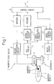
- Fig. 1 is a block diagram illustrating the constitution of a magnetic disk device according to an embodiment of the present invention.
- a magnetic disk device 1 a magnetic disk 2 having a track formed on a disk-like medium of a magnetic film of a high coercive force is maintained rotated, a recording current is supplied to a magnetic head 3 which is disposed being opposed to the magnetic disk 2 to generate a magnetic field from the magnetic head 3, and the magnetic disk 2 is magnetized in a direction of travel of the track to thereby record data in the magnetic disk 2.
- the magnetic head 3 moves in the radial direction of the magnetic disk 2 due to an actuator 4, and records the data into the track of the magnetic disk 2 formed in a concentric manner.
- the magnetic head 3 is further supplied with a recording current from a head IC 5 and generates a magnetic field corresponding to the record data.
- the record data are, first, fed to a control circuit 6 from an external unit.
- the record data used for measuring the NLTS include a reference pattern Ref as reference signals, a to-be-measured pattern Dibit (---00110000---) as to-be-measured signals, Tribit (---00111000---), 2T (---00101000---) and THS (---1010---).
- NLTS will be briefly described.
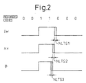
- Fig. 2 is a diagram illustrating an NLTS that occurs at the time of magnetic recording, wherein the abscissa represents the position on the track of the magnetic disk.
- Fig. 2 illustrates a state where the data are recorded from the left toward the right as viewed from the front surface of the paper.
- the upper stage shows codes for recording data
- second and subsequent stages show a recording current Iw of the magnetic head, a magnetic field Hx and a magnetic flux ⁇ of the medium in this order.
- NETS1 occurs for the recording current Iw
- NLTS2 occurs for the magnetic field Hx
- the control circuit 6 receives the above-mentioned record data from an external unit and feeds them to an encoder 7.
- the encoder 7 converts the record data fed from the control circuit 6 into data of NRZ (non-return to zero) and outputs them so as to be recorded into the magnetic disk 2.
- the output signals of the encoder 7 are fed to a record correction circuit 8.
- NRZ is the one called non-return to zero recording system which effects the recording in a pulse waveform in which the length of a gap between the unit codes becomes equal to the length of the pulse in a binary pulse string.
- the record correction circuit 8 detects the arrangement of bits of record signals output from the encoder 7, and effects the correction depending upon the bit arrangement.
- the record signals corrected by the record correction circuit 8 are fed to the head IC 5.
- the head IC 5 feeds, to the magnetic head 3, a recording current corresponding to the record data fed from the record correction circuit 8.
- the signals reproduced by the magnetic head 3 are fed to the head IC 5 and are amplified and are, then, fed to an AGC (automatic gain control) circuit 9.
- the AGC circuit 9 makes the amplitude of the signals fed from the head IC 5 constant and outputs them.
- Signals output from the AGC circuit 9 are fed to a signal detector circuit 10 where the reproduced data are detected.
- the reproduced data detected by the signal detector circuit 10 are fed to a decoder 11 where they are decoded and are, then, fed to the control circuit 6.
- the control circuit 6 outputs the reproduced data to an external unit.
- Signals output from the AGC circuit 9 are fed to a servo demodulator circuit 12.
- the servo demodulator circuit 12 demodulates servo signals from the signals fed from the AGC circuit 9 and feeds them to a servo control circuit 13.
- the servo control circuit 13 In response to a servo signal fed from the servo demodulator circuit 12 and a control signal fed from the control circuit 6, the servo control circuit 13 forms a drive control signal that meets a difference between the present position of the magnetic head 5 and the position at where the recording or reproduction is to be executed, and feeds it to a drive circuit 14.
- the drive circuit 14 In response to the drive control signal fed from the servo control circuit 13, the drive circuit 14 forms a drive signal and feeds it to the actuator 4 to drive it.
- the actuator 4 is driven by the drive signal from the drive circuit 14 and moves the magnetic head 5 to a predetermined position.
- the magnetic disk 2 When the data are to be recorded into the magnetic disk 2 using the above magnetic disk device 1, the magnetic disk 2 must be magnetized. Being affected by the inversion of magnetization of the data recorded into the recording medium, however, the position of the recorded data is deviated; i.e., the position is deviated from the initial position of magnetic inversion.
- Fig. 3 is a block diagram illustrating the constitution of the magnetic disk device according to a second embodiment of the present invention.
- the magnetic disk device 100 shown in Fig. 3 is constituted by an LSI 21 in which the control circuit 16 and the record correction circuit 18 in the magnetic disk device 1 of Fig. 1 is constituted as described below, and a pattern generator circuit 20 is provided between the control circuit 16 and the encoder 7.
- the control circuit 16 operates as described below. That is, the control circuit 16 receives, from an external unit, a command for selecting the record data of a bit-string pattern that forms reference signals or to-be-measured signals fed to the encoder 7, and feeds them to the pattern generator circuit 20. The control circuit 16 further feeds the calculated result of NLTS by the fifth harmonic method that will be described later to the record correction circuit 18. In response to the calculated result of NLTS that is fed, the record correction circuit 18 feeds the compensated record signal to the head IC 5.
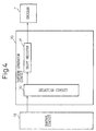
- Fig. 4 is a block diagram illustrating the constitution of an embodiment of the pattern generator circuit used for the magnetic disk device of Fig. 3.
- the pattern generator circuit 20 selects a record data out of a reference pattern Ref (---11110000---) of reference signals, a to-be-measured pattern Dibit (---00110000---) of to-be-measured signals, a Tribit (---00111000---), a 2T (---00101000---) and an HTS (---1010---) each consisting of 30 bits and being stored in advance in a nonvolatile memory (not shown) in a selection circuit 30, and feeds the record data of 30 bits to a shift register 31.
- the shift register 31 is a 30-bit parallel-input series-output shift register which writes parallel record data of 30 bits when the S/L mode is 0, and cyclically and serially shifts the written data bit by bit from an optional bit when the S/L mode is 1 and feeds it to the encoder 7. Thus, the record data of 30 bits is fed to the encoder 7.
- the magnetic disk device of the present invention it is also possible to provide a high-speed Fourier transform unit (FFT; not shown) between the AGC circuit 9 and the signal detector circuit 10 in the LSI 21, in order to detect a fifth harmonic component from the reproduced signal output from the AGC control circuit 9 and to output the fifth harmonic component to an external unit through the control circuit 16.
- FFT Fourier transform
- the method of measuring the NLTS comprises the following three steps.
- reference signals which repeat a bit-string pattern of 30 T with the pulse width of each bit being T and the polarity being inverted every after 15 bits (15 T) are sent to the control circuit 6 from the external unit, the data are recorded into the magnetic disk 2, the reproduced signals thereof are detected from the outputs of the AGC circuit 9, and a fifth harmonic component (hereinafter referred to as a fifth component) is measured by using a spectrum analyzer or an FFC.
- the fifth component is denoted by V5ref.
- the reference signals are expressed below by the NRZ notation which expresses the codes for recording the data in the magnetic disk 2 in terms of the levels and by the NRZI notation which expresses the codes for recording in terms of the inversion of levels.
- the data are recorded into the magnetic disk 2 by using the to-be-measured signals which repeat a bit-string pattern of 30 T including a Dibit pattern, and a fifth component V5pat of the reproduced signals is measured by using the spectrum analyzer or the FFC.
- the to-be-measured signals are expressed below by the NRZ notation and by the NRZI notation. To-be-measured signals: NRZ notation 100000001111111 011111110000000 NRZI notation 110000001000000 110000001000000
- the NLTS (Dibit) occurring with the Dibit is calculated from the following formula (1).
- NLTS is a value normalized with 1T, i.e., a value of when the pulse width of 1 T is set to be 1 (100%).
- NLTS (Dibit) acos [(2 - Vab 2 )/2] * 3/ ⁇
- the measurement of the NLTS based on the fifth harmonic method by using various to-be-measured patterns is measured.
- a reference pattern is used in common, various to-be-measured patterns are provided, and the fifth harmonic wave is measured.
- selecting the to-be-measured patterns there is used a reproduced signal in which the non-linearity of the MR head is modeled, and a pattern durable against non-linearity of MR is selected.
- Fig. 5 is a block diagram illustrating of the device for magnetic recording/reproduction for measuring the non-linearity of a medium in the magnetic recording/reproduction according to an embodiment of the present invention.
- a reference signal or a signal to be measured is recorded into a medium 53 from a pattern generator 51 through recording means 52.
- the data recorded in the medium 53 is input to a first high-speed Fourier transform unit FFT 55 through reproducing means 54.
- the reference signal or the signal to be measured is input to a second high-speed Fourier transform unit FFT 56 from the pattern generator 51.
- Fig. 6 is a diagram illustrating an example of outputs of the Fast Fourier Transform unit FFT, wherein the abscissa represents the frequency component of when the reference signals or the signals to be measured are input to the FFT 55 or to the FFT 56 of Fig. 5, and the ordinate represents the FFT outputs.
- a divider 57 picks up a fifth component FFT 0 in the signal recorded in, and reproduced from, the medium relying on the output of the FFT 55, picks up a fifth component FFT I in the signal recorded in, and reproduced from, the medium relying on the output of the FFT 56, and a calculates value of division FFT 0 / FFT i .
- NLTS measuring means 58 is formed of, for example, firmware. A nonlinear NLTS is calculated in compliance with the above-mentioned formula (1) by using a calculated result of the divider 57, and the thus calculated result is sent to a control circuit 59.
- non-linearity occurs in the transmission system between the pattern generator 51 and the recording means 52, between the recording means 52 and the medium 53, between the medium 53 and the reproducing means 54, and between the reproducing means 54 and the FFT 55.
- Non-linearly doe not occur in the transmission system between the pattern generator 51 and the FFT 56.
- the FFT 0 and FFT I have the same particular frequency (fifth component), and there occurs no error in the frequency characteristics. As a result, the non-linearity can be measured without affected by the frequency characteristics of the transmission system.
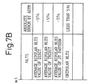
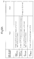
- Figs. 7A and 7B show a table listing various recording patterns of the reference signals and of the to-be-measured signals used in the measurement of NLTS by the fifth harmonic method.
- the upper stage shows the items of the columns in which, from the left, the first column includes the kinds of measurement of NLTS, the second column includes the recording patterns, the third column includes the NLTSs, and the fourth column includes absolute errors due to asymmetry.
- the first column from the left includes the kinds of NLTS measurement, such as bipolarities of the to-be-measured pattern Dibit (---00110000---), Tribit (---00111000---) and 2T (---00101000---), monopolarity of HTS (---1010---) and reference measuring pattern Ref (---10001000---).
- NLTS measurement such as bipolarities of the to-be-measured pattern Dibit (---00110000---), Tribit (---00111000---) and 2T (---00101000---), monopolarity of HTS (---1010---) and reference measuring pattern Ref (---10001000---).
- the second column from the left includes the reference patterns and the to-be-measured patterns expressed by the NRZI notation.
- the data selected from these patterns are repetitively fed as record data every after 30 T to the control circuit 16 from the external unit.
- the third column from the left includes NLTSs which are, successively from the upper side, average bipolar NLTS values of the to-be-measured pattern Dibit, Tribit and 2T and a unipolar NLTS of the to-be-measured pattern HTS.
- the fourth column from the left includes absolute errors due to asymmetry.
- the errors can be calculated from an induced voltage detected as a signal of record data reproduced by the magnetic head 3.
- Er (Vp + - VP - )/2 * (Vp + - VP - ) where Er is an error, Vp + is an absolute peak value of the positive induced voltage, and Vp- is an absolute peak value of the negative induced voltage.
- Figs. 8A and 8B show a table listing formulas for calculating the NLTS by the fifth harmonic method shown in Figs. 7A and 7B.
- the upper stage shows the items of the columns in which a first column from the left includes the kinds of NLTS measurement, the second column includes the fifth harmonic components V5pat of the to-be-measured signals, the third column includes the fifth harmonic components V5ref of the reference signals, the fourth column includes the ratios Vab of the fifth harmonic components, and the fifth column include strict solutions and approximate solutions of the formulas for calculating the NLTS.
- the first column from the left includes bipolarities of the kinds of the NLTS measurement such as Dibit, Tribit, 2T, and unipolarity of an HTS.
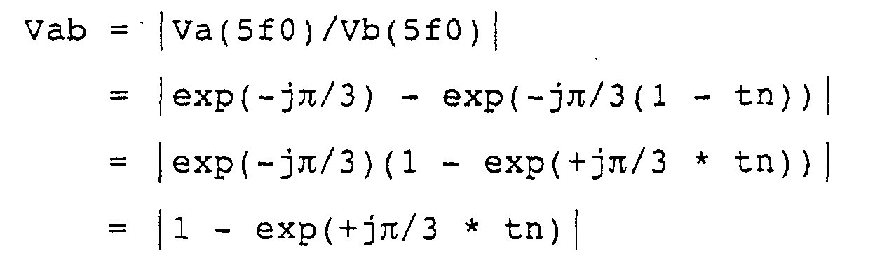
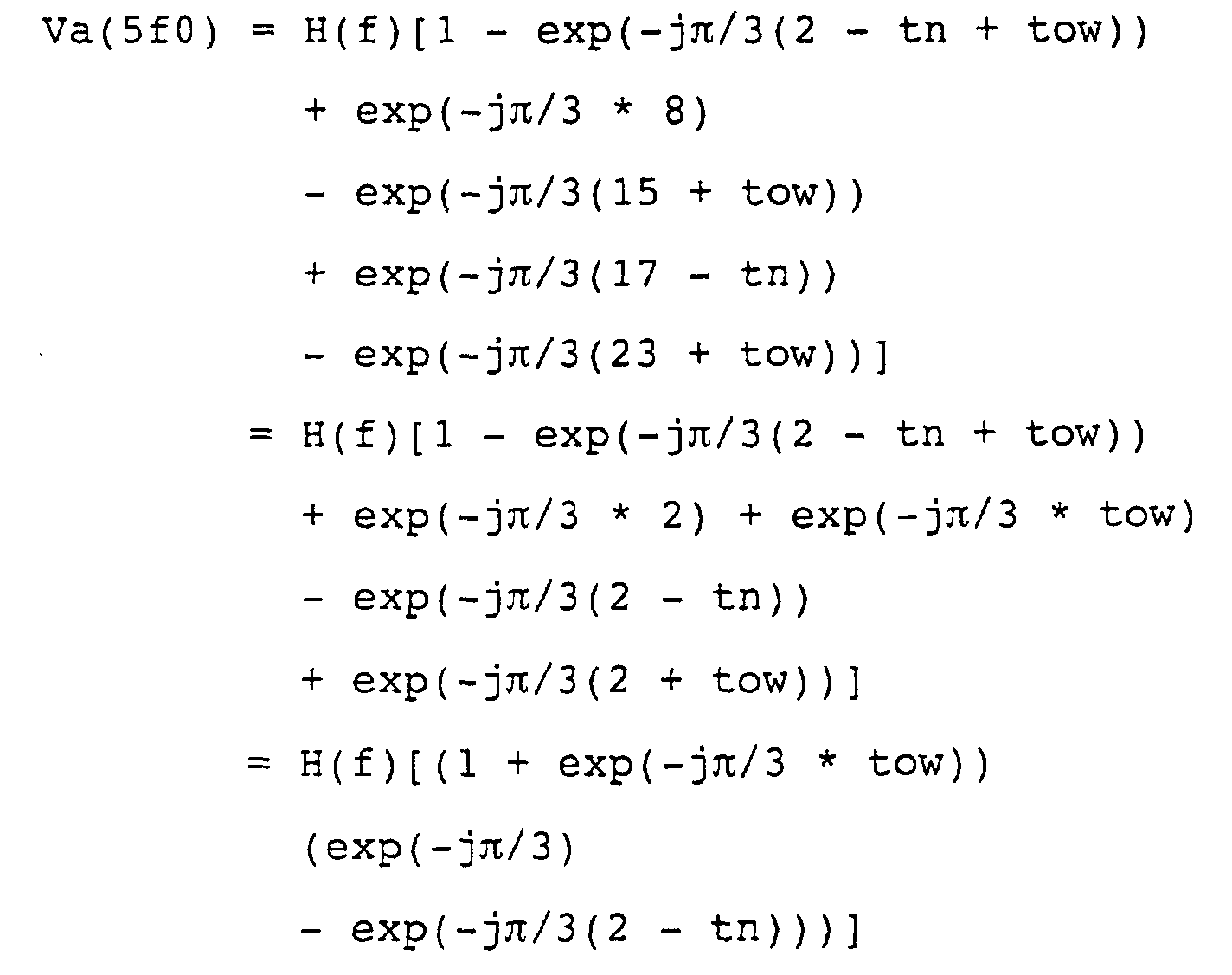
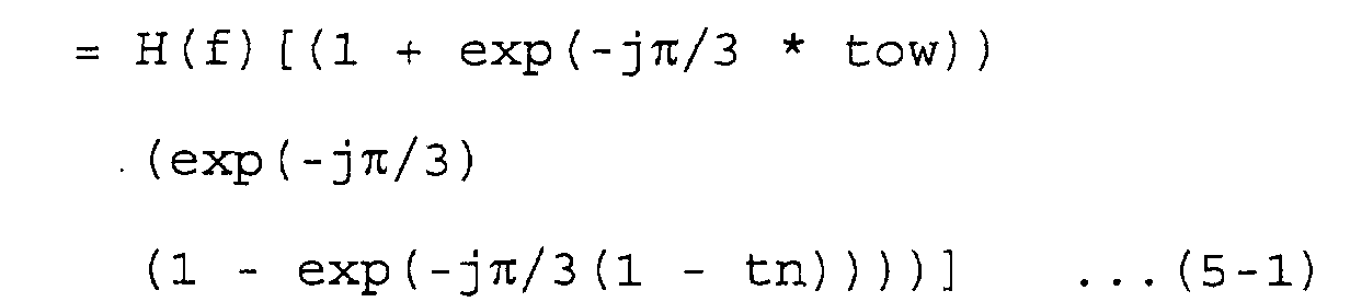
- nlts denotes the NLTS of when the preceding bit is being recorded or reproduced
- ow denotes the NLTS of data written before recording.
- the measurable NLTS in the continuation of magnetic inversion is the NLTS of the second bit in the case of the Dibit, is the NLTS of the third bit in the case of the Tribit, and is the NLTS that occurs at a frequency one-half that of the Dibit in the case of the 2T.
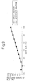
- Fig. 9 is a diagram illustrating the results of calculating the NLTSs in simulating various NLTSs in a linear reproducing transmission line according to a previously-proposed method
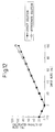
- Figs. 10 to 12 are diagrams illustrating the results of calculating the NLTSs in simulating various NLTSs in a linear reproducing transmission line according to an embodiment of the present invention
- Fig. 9 illustrating the results of calculating the NLTSs by using the Dibit pattern as the to-be-measured signals
- Fig. 10 illustrating the results of calculating the NLTSs by using the Tribit pattern as the to-be-measured signals
- Fig. 9 is a diagram illustrating the results of calculating the NLTSs in simulating various NLTSs in a linear reproducing transmission line according to an embodiment of the present invention
- Fig. 9 illustrating the results of calculating the NLTSs by using the Dibit pattern as the to-be-measured signals
- Fig. 10 illustrating the results of calculating
- Fig. 11 illustrating the results of calculating the NLTSs by using the 2T pattern as the to-be-measured signals
- Fig. 12 illustrating the results of calculating the NLTSs by using the HTS (O/W NLTS) pattern as the to-be-measured signals.
- Figs. 13 to 15 are diagrams illustrating the results of calculating the NLTSs in simulating various NLTSs in a non-linear reproducing transmission line, and correspond to Figs. 9 to 12, respectively, Fig. 13 illustrating the results of calculating the NLTSs by using the Dibit pattern as the to-be-measured signals, Fig. 14 illustrating the results of calculating the NLTSs by using the Tribit pattern as the to-be-measured signals, Fig. 15 illustrating the results of calculating the NLTSs by using the 2T pattern as the to-be-measured signals, and Fig. 16 illustrating the results of calculating the NLTSs by using the HTS (O/W NLTS) pattern as the to-be-measured signals.
- HTS HTS
- Figs. 13A, 14A, 15A and 16A are diagrams illustrating the results of measuring the NLTSs by the fifth harmonic method while changing the NLTS by the record data of one bit before from 0% to 30%.
- Figs. 13B, 14B, 15B and 16B are diagrams illustrating the results of measuring the NLTSs by the fifth harmonic method while fixing the NLTS by the record data of one bit before to 0% in Figs. 13A, 14A, 15A and 16A.
- the measuring method can be carried out relying only upon the harmonics method irrespective of the kind of NLTS and, besides, the reference signals can be used in common. Accordingly, a variety kinds of NLTSs can be accomplished by simply changing the pattern to be measured and the formula for calculation.
- various NLTSs can be measured even in a system in which MR non-linearity exists and the NLTSs can be easily modeled in the head medium system and the write precompensation circuit (WPC) can be optimized in a form which assures reliable measurement.
- the WPC can be optimized by using a value of ratio Vab of the fifth components of the reference signals and of the to-be-measured signals without the need of calculating the NLTSs using the formulas.
- the NLTSs become the smallest as Vab approaches 1.
- the NLTS can be measured involving a measuring error of about 5% even by taking the non-linearity of the MR-type reproduction head into consideration.
- a device for magnetic recording/reproduction is capable of measuring the NLTS by itself.
Landscapes
- Engineering & Computer Science (AREA)
- Signal Processing (AREA)
- Digital Magnetic Recording (AREA)
- Recording Or Reproducing By Magnetic Means (AREA)
- Testing, Inspecting, Measuring Of Stereoscopic Televisions And Televisions (AREA)
- Measuring Magnetic Variables (AREA)
Abstract
Description
| Reference signals: | ||
| NRZ notation | 111111111111111 | 000000000000000 |
| NRZI notation | 100000000000000 | 100000000000000 |
| To-be-measured signals: | ||
| NRZ notation | 100000001111111 | 011111110000000 |
| NRZI notation | 110000001000000 | 110000001000000 |
said plural kinds of predetermined bit-string patterns include:
| Reference signals: | ||
| NRZ notation | 111111111111111 | 000000000000000 |
| NRZI notation | 100000000000000 | 100000000000000 |
| To-be-measured signals: | ||
| NRZ notation | 100000001111111 | 011111110000000 |
| NRZI notation | 110000001000000 | 110000001000000 |
○ Calculation of the fifth component of a pattern A.
Positions of inversion of magnetization of the pattern A: [0, 1, 8, 15, 16, 23] The NLTS by the preceding bit normalized with a bit period T is denoted by tn, and the NLTS by the previously recorded data that is normalized is denoted by tow.

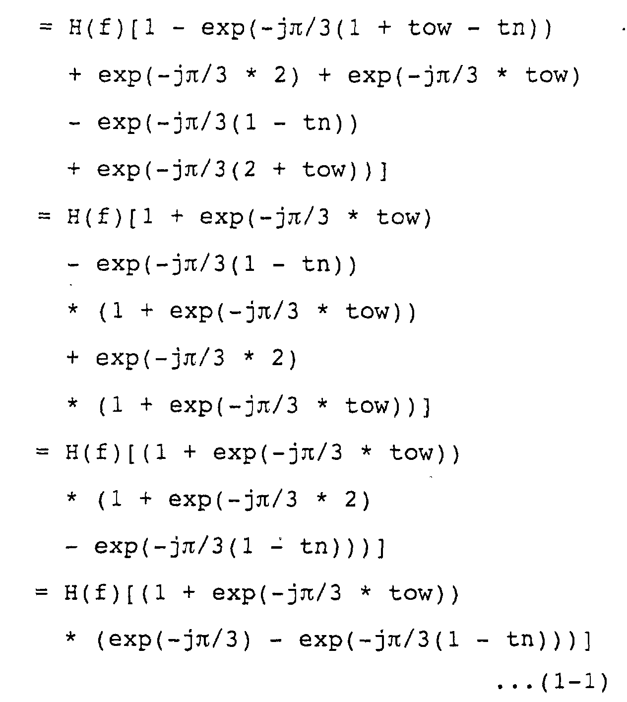



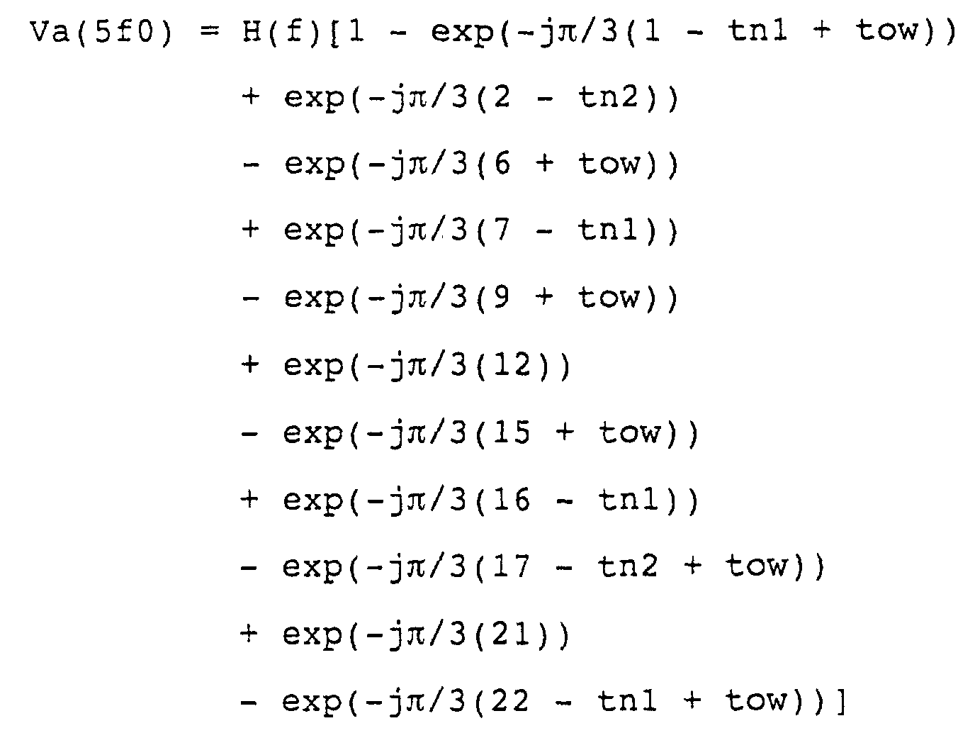
○ Calculation of the fifth component of the pattern A. Positions of inversion of magnetization of the pattern A: [0, 1, 2, 6, 7, 9, 12, 15, 16, 17, 21, 22]
Similarly to calculating the Dibit NLTS,


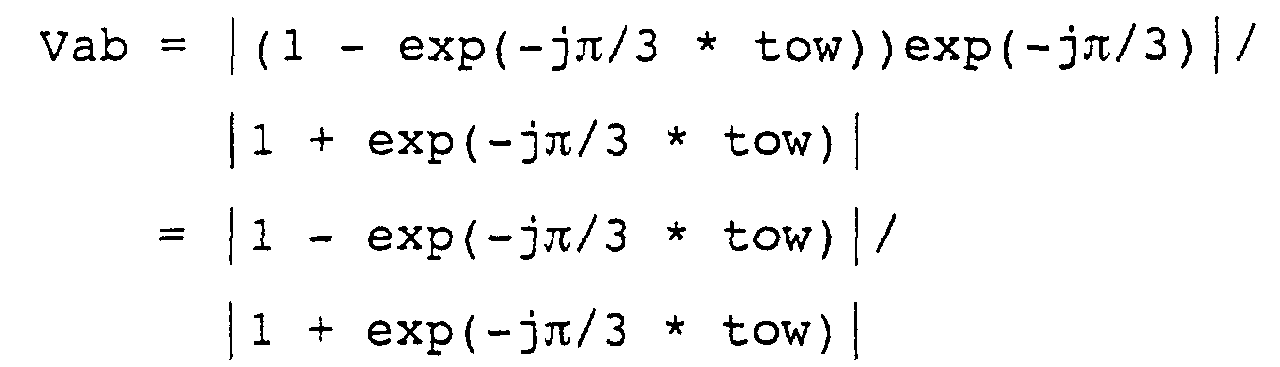
○ Calculating the fifth component of the pattern A. Positions of inversion of magnetization of the pattern A: [0, 2, 4, 6, 8, 12, 14, 16, 18, 20] Like when calculating the Dibit NLTS,


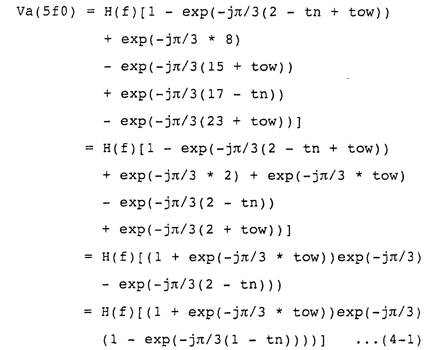
○ Calculating the fifth component of the pattern A.
Positions of inversion of magnetization of the pattern A: [0, 2, 8, 15, 17, 23]
Like when calculating the above Dibit NLTS,


○ Fundamental frequency component VF2 of the reference
pattern: period 4T
Position of inversion of magnetization of the pattern A: [0, 2]

Claims (33)
- A method of measuring non-linearity in the input/output of an object which receives input signals and produces output signals in response to the input signals, comprising the steps of:feeding signals of a reference pattern to said object to measure a first predetermined harmonic component from the output signals thereof;selecting signals of a pattern from signals of plural kinds of predetermined patterns;feeding signals of said selected pattern to said object cyclically to measure a second predetermined harmonic component from the output signals thereof; andcalculating a non-linear transition shift NLTS in said object from said first predetermined harmonic component and from said second predetermined harmonic component.
- A method of measuring non-linearity in the magnetic recording/reproduction of a medium comprising the steps of:measuring a first predetermined harmonic component from the reproduced signals of the reference signals magnetically recorded in a medium;measuring a second predetermined harmonic component from the reproduced signals for each of the plural kinds of to-be-measured signals magnetically recorded in said medium; andcalculating a non-linear transition shift NLTS in the magnetic recording/reproduction from said first predetermined harmonic component and from said second predetermined harmonic component corresponding to each of the to-be-measured signals.
- A measuring method according to claim 2 above, wherein said predetermined harmonic component is a fifth harmonic component.
- A measuring method according to claim 3 above, wherein said reference signals are the ones obtained by cyclically and serially shifting, from an optional bit, the data of a bit-string pattern for magnetically recording the data into said medium by once effecting the magnetization and demagnetization for the same period of time, respectively; and wherein
said plural kinds of predetermined bit-string patterns include:a first pattern of bit strings each including a tribit in which the magnetic inversion occurs continuously for three bits in each period of said magnetization and demagnetization;a second pattern of bit strings each including 2T in which the magnetic inversion occurs after an interval of two bits in each period of said magnetization and demagnetization; anda third pattern of bit strings including a bit constitution HTS in which the magnetic inversion occurs in a manner that the magnetization occurs in a direction opposite to the direction of magnetization of the record in the medium. - A measuring method according to claim 4 above, wherein, when a bit that undergoes the magnetic inversion is denoted by 1, said reference signals are those signals repeating a pattern of a 30-bit string of 100000000000000 100000000000000 in which the magnetic inversion occurs at the 0th bit and at the 15th bit, and said first pattern is a 30-bit string of 111000110100100 111000110000000 in which the magnetic inversion occurs at the 0th, 1st, 2nd, 6th, 7th, 9th, 12th, 15th, 17th and 21st bits and at the 22nd bit.
- A measuring method according to claim 4 above, wherein, when a bit that undergoes the magnetic inversion is denoted by 1, said reference signals are those signals repeating a pattern of a 30-bit string of 100000000000000 100000000000000 in which the magnetic inversion occurs at the 0th bit and at the 15th bit, and said second pattern is a 30-bit string of 101000001000000 101000001000000 in which the magnetic inversion occurs at the 0th, 2nd, 8th, 15th and 17th bits and at the 23rd bit.
- A measuring method according to claim 4 above, wherein, when a bit that undergoes the magnetic inversion is denoted by 1, said reference signals are those signals repeating a pattern of a 30-bit string of 100000000000000 100000000000000 in which the magnetic inversion occurs at the 0th bit and at the 15th bit, and said third pattern is a 30-bit string of 101010101000101 010101000000000 in which the magnetic inversion occurs at the 0th, 2nd, 4th, 6th, 8th, 12th, 14th, 16th and 18th bits and at the 20th bit.
- A measuring method according to any one of claims 2 to 7, wherein said NLTS is measured within an error range of 5%.
- An LSI for magnetic recording/reproduction which generates reference signals that are to be magnetically recorded into a medium, measures a first predetermined harmonic component from the reproduced signals thereof, generates to-be-measured signals corresponding to said reference signals that are to be magnetically recorded into said medium, and measures a second predetermined harmonic component from the reproduced signals thereof, wherein there is incorporated a circuit for generating a bit-string pattern in common with said plural kinds of bit-string patterns and plural kinds of predetermined bit-string patterns forming said to-be-measured signals.
- An LSI for magnetic recording/reproduction which generates reference signals that are to be magnetically recorded into a medium, measures a first predetermined harmonic component from the reproduced signals thereof, generates to-be-measured signals corresponding to said reference signals that are to be magnetically recorded into said medium, and measures a second predetermined harmonic component from the reproduced signals thereof, wherein there is incorporated a circuit for measuring a predetermined harmonic component from said reference signals and from the reproduced signals of plural to-be-measured signals corresponding to one of said reference signals.
- An LSI for magnetic recording/reproduction which generates reference signals that are to be magnetically recorded into a medium, measures a first predetermined harmonic component from the reproduced signals thereof, generates to-be-measured signals corresponding to said reference signals that are to be magnetically recorded into said medium, and measures a second predetermined harmonic component from the reproduced signals thereof, wherein there are incorporated a circuit for generating a bit-string pattern forming said reference signals and a predetermined bit-string pattern forming said to-be-measured signals, and a circuit for measuring a predetermined harmonic component from said reference signals recorded in said medium and from the reproduced signals said to-be-measured signals.
- An LSI according to claim 9 or 11 above, wherein, when a bit that undergoes the magnetic inversion is denoted by 1, said reference signals are those signals repeating a pattern of a 30-bit string of 100000000000000 100000000000000 in which the magnetic inversion occurs at the 0th bit and at the 15th bit, and said first pattern is a 30-bit string of 111000110100100 111000110000000 in which the magnetic inversion occurs at the 0th, 1st, 2nd, 6th, 7th, 9th, 12th, 15th, 17th and 21st bits and at the 22nd bit.
- An LSI according to claim 9 or 11 above, wherein, when a bit that undergoes the magnetic inversion is denoted by 1, said reference signals are those signals repeating a pattern of a 30-bit string of 100000000000000 100000000000000 in which the magnetic inversion occurs at the 0th bit and at the 15th bit, and said second pattern is a 30-bit string of 101000001000000 101000001000000 in which the magnetic inversion occurs at the 0th, 2nd, 8th, 15th and 17th bits and at the 23rd bit.
- An ISL according to claim 9 or 11 above, wherein, when a bit that undergoes the magnetic inversion is denoted by 1, said reference signals are those signals repeating a pattern of a 30-bit string of 100000000000000 100000000000000 in which the magnetic inversion occurs at the 0th bit and at the 15th bit, and said third pattern is a 30-bit string of 101010101000101 010101000000000 in which the magnetic inversion occurs at the 0th, 2nd, 4th, 6th, 8th, 12th, 14th, 16th and 18th bits and at the 20th bit.
- An LSI for magnetic recording/reproduction according to claim 9 above, wherein said LSI for magnetic recording/reproduction includes a circuit for measuring the fifth harmonic component from the reproduced signals of the data read from said medium in which the data have been stored using said reference signals or said to-be-measured signals.
- An LSI for magnetic recording/reproduction according to claim 15 above, wherein said LSI for magnetic recording/reproduction includes a circuit for calculating a ratio Vab (= V5pat/V5ref) of a second fifth harmonic component V5pat which is a reproduced signal of the data read from said medium in which the data have been recorded using said to-be-measured signals to a first fifth harmonic component V5ref which is a reproduced signal of the data from said medium in which the data have been recorded by using said reference signals.
- An LSI for magnetic recording/reproduction according to claim 16 above, wherein said LSI for magnetic recording/reproduction includes a circuit for calculating a non-linear transition shift NLTS in the magnetic recording/reproduction based upon said ratio Vab (= V5pat/V5ref) calculated from said first fifth harmonic component V5ref and said second fifth harmonic component V5pat.
- An LSI for magnetic recording/reproduction according to any one of claims 10, 15, 16 or 17 (above), wherein said circuit for measuring the fifth harmonic component includes a high-speed Fourier transform circuit.
- An LSI for magnetic recording/reproduction according to any one of claims 9 to 18 above, wherein said LSI for magnetic recording/reproduction includes a circuit for adjusting a write compensation circuit based upon said fifth harmonic component.
- A device for magnetic recording/reproduction mounting an LSI for magnetic recording/reproduction of any one of claims 9 to 19.
- A device for magnetic recording/reproduction for measuring the non-linearity in the magnetic recording/reproduction of a medium by generating reference signals that are to be magnetically recorded into a medium, measuring a first predetermined harmonic component from the reproduced signals thereof, generating to-be-measured signals corresponding to said reference signals that are to be magnetically recorded into said medium, measuring a second predetermined harmonic component from the reproduced signals thereof, and calculating a non-linear transition shift NLTS in said magnetic recording/reproduction from said first predetermined harmonic component and said second predetermined harmonic component, wherein there are provided means for selecting data of a bit-string pattern from the data of a bit-string pattern in common with said plural kinds of bit-string patterns and of plural kinds of predetermined bit-string patterns forming said to-be-measured signals, and means for generating said reference signals or said to-be-measured signals by cyclically and serially shifting the data of said selected bit-string pattern starting from any bit.
- A device for magnetic recording/reproduction for measuring the non-linearity in the magnetic recording/reproduction of a medium by generating reference signals that are to be magnetically recorded into a medium, measuring a first predetermined harmonic component from the reproduced signals thereof, generating to-be-measured signals corresponding to said reference signals that are to be magnetically recorded into said medium, measuring a second predetermined harmonic component from the reproduced signals thereof, and calculating a non-linear transition shift NLTS in said magnetic recording/reproduction from said first predetermined harmonic component and said second predetermined harmonic component, wherein there is provided means for measuring a predetermined harmonic component from said reference signals and from a reproduced signal of a to-be-measured signal corresponding to one of said reference signals.
- A device for magnetic recording/reproduction for measuring the non-linearity in the magnetic recording/reproduction of a medium by generating reference signals that are to be magnetically recorded into a medium, measuring a first predetermined harmonic component from the reproduced signals thereof, generating to-be-measured signals corresponding to said reference signals that are to be magnetically recorded into said medium, measuring a second predetermined harmonic component from the reproduced signals thereof, and calculating a non-linear transition shift NLTS in said magnetic recording/reproduction from said first predetermined harmonic component and said second predetermined harmonic component, wherein there are provided means for generating said reference signals or said to-be-measured signals by selecting data of a bit-string pattern from the data of the bit-string pattern forming said reference signals and of a predetermined bit-string pattern forming said to-be-measured signals, and cyclically and serially shifting the data of said selected bit-string pattern starting from any bit, and means for measuring a predetermined harmonic component from the reproduced signals of the data read from said medium in which the data have been recorded by using said reference signals and said to-be-measured signals recorded in said medium.
- A device according to claim 21 or 23 above, wherein, when a bit that undergoes the magnetic inversion is denoted by 1, said reference signals are those signals repeating a pattern of a 30-bit string of 100000000000000 100000000000000 in which the magnetic inversion occurs at the 0th bit and at the 15th bit, and said first pattern is a 30-bit string of 111000110100100 111000110000000 in which the magnetic inversion occurs at the 0th, 1st, 2nd, 6th, 7th, 9th, 12th, 15th, 17th and 21st bits and at the 22nd bit.
- A device according to claim 21 or 23 above, wherein, when a bit that undergoes the magnetic inversion is denoted by 1, said reference signals are those signals repeating a pattern of a 30-bit string of 100000000000000 100000000000000 in which the magnetic inversion occurs at the 0th bit and at the 15th bit, and said second pattern is a 30-bit string of 101000001000000 101000001000000 in which the magnetic inversion occurs at the 0th, 2nd, 8th, 15th and 17th bits and at the 23rd bit.
- A device according to claim 21 or 23 above, wherein, when a bit that undergoes the magnetic inversion is denoted by 1, said reference signals are those signals repeating a pattern of a 30-bit string of 100000000000000 100000000000000 in which the magnetic inversion occurs at the 0th bit and at the 15th bit, and said third pattern is a 30-bit string of 101010101000101 010101000000000 in which the magnetic inversion occurs at the 0th, 2nd, 4th, 6th, 8th, 12th, 14th, 16th and 18th bits and at the 20th bit.
- A device for magnetic recording/reproduction according to claim 21 above, wherein said LSI for magnetic recording/reproduction includes a circuit for measuring the fifth harmonic component from the reproduced signals of the data read from said medium in which the data have been stored using said reference signals or said to-be-measured signals.
- A device for magnetic recording/reproduction according to claim 27 above, wherein said LSI for magnetic recording/reproduction includes a circuit for calculating a ratio Vab (= V5pat/V5ref) of a second fifth harmonic component V5pat which is a reproduced signal of the data read from said medium in which the data have been recorded using said to-be-measured signals to a first fifth harmonic component V5ref which is a reproduced signal of the data from said medium in which the data have been recorded by using said reference signals.
- A device for magnetic recording/reproduction according to claim 27 above, wherein said LSI for magnetic recording/reproduction includes a circuit for calculating a non-linear transition shift NLTS in the magnetic recording/reproduction based upon said ratio Vab (= V5pat/V5ref) calculated from said first fifth harmonic component V5ref and said second fifth harmonic component V5pat.
- A device for magnetic recording/reproduction according to any one of claims 22, 27, 28 and 29 above, wherein said means for measuring the fifth harmonic component includes a Fast Fourier Transform unit.
- A device for magnetic recording/reproduction according to any one of claims 21 to 30 above, wherein said device for magnetic recording/reproduction includes means for adjusting a write compensation circuit based upon said fifth harmonic component.
- A device for magnetic recording/reproduction according to any one of claims 21 to 31 above, wherein said device for magnetic recording/reproduction includes a magnetic reluctance-type head for detecting said reproduced signals.
- A device for magnetic recording/reproduction according to any one of claims 20 to 32 above, wherein said NLTS is measured within an error range of 5%.
Priority Applications (2)
| Application Number | Priority Date | Filing Date | Title |
|---|---|---|---|
| EP07113926A EP1852854A1 (en) | 2000-11-30 | 2001-11-29 | Method of measuring non-linearity in magnetic recording/reproduction, device for magnetic recording/reproduction and LSI for magnetic recording/reproduction |
| EP07113925A EP1852853A1 (en) | 2000-11-30 | 2001-11-29 | Method of measuring non-linearity in magnetic recording/reproduction, device for magnetic recording/reproduction and LSI for magnetic recording/reproduction |
Applications Claiming Priority (4)
| Application Number | Priority Date | Filing Date | Title |
|---|---|---|---|
| JP2000365874 | 2000-11-30 | ||
| JP2000365874 | 2000-11-30 | ||
| JP2001310365A JP3870333B2 (en) | 2000-11-30 | 2001-10-05 | Magnetic recording / reproducing apparatus and LSI for magnetic recording / reproducing |
| JP2001310365 | 2001-10-05 |
Related Child Applications (2)
| Application Number | Title | Priority Date | Filing Date |
|---|---|---|---|
| EP07113926A Division EP1852854A1 (en) | 2000-11-30 | 2001-11-29 | Method of measuring non-linearity in magnetic recording/reproduction, device for magnetic recording/reproduction and LSI for magnetic recording/reproduction |
| EP07113925A Division EP1852853A1 (en) | 2000-11-30 | 2001-11-29 | Method of measuring non-linearity in magnetic recording/reproduction, device for magnetic recording/reproduction and LSI for magnetic recording/reproduction |
Publications (3)
| Publication Number | Publication Date |
|---|---|
| EP1211672A2 true EP1211672A2 (en) | 2002-06-05 |
| EP1211672A3 EP1211672A3 (en) | 2006-02-01 |
| EP1211672B1 EP1211672B1 (en) | 2009-03-11 |
Family
ID=26605002
Family Applications (3)
| Application Number | Title | Priority Date | Filing Date |
|---|---|---|---|
| EP07113926A Withdrawn EP1852854A1 (en) | 2000-11-30 | 2001-11-29 | Method of measuring non-linearity in magnetic recording/reproduction, device for magnetic recording/reproduction and LSI for magnetic recording/reproduction |
| EP01309999A Expired - Lifetime EP1211672B1 (en) | 2000-11-30 | 2001-11-29 | Method of measuring non-linearity in magnetic recording/reproduction, device for magnetic recording/reproduction and LSI for magnetic recording/reproduction |
| EP07113925A Withdrawn EP1852853A1 (en) | 2000-11-30 | 2001-11-29 | Method of measuring non-linearity in magnetic recording/reproduction, device for magnetic recording/reproduction and LSI for magnetic recording/reproduction |
Family Applications Before (1)
| Application Number | Title | Priority Date | Filing Date |
|---|---|---|---|
| EP07113926A Withdrawn EP1852854A1 (en) | 2000-11-30 | 2001-11-29 | Method of measuring non-linearity in magnetic recording/reproduction, device for magnetic recording/reproduction and LSI for magnetic recording/reproduction |
Family Applications After (1)
| Application Number | Title | Priority Date | Filing Date |
|---|---|---|---|
| EP07113925A Withdrawn EP1852853A1 (en) | 2000-11-30 | 2001-11-29 | Method of measuring non-linearity in magnetic recording/reproduction, device for magnetic recording/reproduction and LSI for magnetic recording/reproduction |
Country Status (5)
| Country | Link |
|---|---|
| US (1) | US6934100B2 (en) |
| EP (3) | EP1852854A1 (en) |
| JP (2) | JP3870333B2 (en) |
| KR (2) | KR100808611B1 (en) |
| DE (1) | DE60137899D1 (en) |
Families Citing this family (31)
| Publication number | Priority date | Publication date | Assignee | Title |
|---|---|---|---|---|
| WO2004097804A1 (en) * | 2003-04-25 | 2004-11-11 | Fujitsu Limited | Non-linearity measuring method, non-linearity measuring device, magnetic recording/reproducing device, amd magnetic recording/reproducing lsi |
| US7248424B2 (en) | 2003-04-25 | 2007-07-24 | Fujitsu Limited | Nonlinearity measuring method, nonlinearity measuring unit, magnetic recording/regenerating unit and LSI for magnetic recording/regenerating |
| US7889448B2 (en) * | 2004-11-15 | 2011-02-15 | Hitachi Global Storage Technologies, Netherlands, B.V. | Magnetic spacing measurement |
| US7193801B2 (en) * | 2004-11-18 | 2007-03-20 | Agere Systems, Inc. | Method and apparatus for testing a servo circuit of a read/write head system |
| JP4504928B2 (en) * | 2006-01-18 | 2010-07-14 | 新科實業有限公司 | Method for evaluating characteristics of write element of thin film magnetic head |
| US8441752B1 (en) * | 2006-08-30 | 2013-05-14 | Marvell International Ltd. | Dibit pulse extraction methods and systems |
| KR20100025508A (en) * | 2007-05-18 | 2010-03-09 | 지라텍스 테크놀로지 리미티드 | Apparatus and methods of generating a test pattern of data, analysing a test pattern of data, and testing a data storage disk medium and/or a read/write head |
| JP2009074941A (en) * | 2007-09-20 | 2009-04-09 | Fujitsu Ltd | Method and apparatus for measuring amplitude of periodic signal and magnetic head test method and apparatus |
| JP2009087440A (en) * | 2007-09-28 | 2009-04-23 | Fujitsu Ltd | Control device, storage device, LSI, and recording compensation method |
| CN101743591B (en) | 2007-12-21 | 2013-03-06 | Lsi公司 | Systems and methods for adaptive equalization in recording channels |
| US7924523B2 (en) * | 2007-12-21 | 2011-04-12 | Lsi Corporation | Frequency domain approach for efficient computation of fixed-point equalization targets |
| US7924518B2 (en) * | 2008-08-27 | 2011-04-12 | Lsi Corporation | Systems and methods for adaptive write pre-compensation |
| US7859780B2 (en) * | 2008-08-27 | 2010-12-28 | Agere Systems Inc. | Systems and methods for on-the-fly write pre-compensation estimation |
| US9281908B2 (en) * | 2008-10-08 | 2016-03-08 | Avago Technologies General Ip (Singapore) Pte. Ltd. | Systems and methods for memory efficient signal and noise estimation |
| US8154815B2 (en) * | 2008-12-18 | 2012-04-10 | Lsi Corporation | Systems and methods for generating equalization data using shift register architecture |
| US7929240B2 (en) * | 2008-12-18 | 2011-04-19 | Lsi Corporation | Systems and methods for adaptive MRA compensation |
| US7965467B2 (en) * | 2008-12-18 | 2011-06-21 | Lsi Corporation | Systems and methods for generating equalization data |
| US7948702B2 (en) * | 2008-12-18 | 2011-05-24 | Lsi Corporation | Systems and methods for controlling data equalization |
| US7974030B2 (en) | 2008-12-23 | 2011-07-05 | Lsi Corporation | Systems and methods for dibit correction |
| US7948699B2 (en) * | 2009-01-02 | 2011-05-24 | Lsi Corporation | Systems and methods for equalizer optimization in a storage access retry |
| US7957251B2 (en) | 2009-02-16 | 2011-06-07 | Agere Systems Inc. | Systems and methods for reduced latency loop recovery |
| US7969337B2 (en) * | 2009-07-27 | 2011-06-28 | Lsi Corporation | Systems and methods for two tier sampling correction in a data processing circuit |
| US8139305B2 (en) * | 2009-09-14 | 2012-03-20 | Lsi Corporation | Systems and methods for timing and gain acquisition |
| JP2012009108A (en) * | 2010-06-24 | 2012-01-12 | Toshiba Corp | Non-linear property measurement apparatus, non-linear property measuring method and magnetic recording replay device |
| US8854752B2 (en) | 2011-05-03 | 2014-10-07 | Lsi Corporation | Systems and methods for track width determination |
| US8762440B2 (en) | 2011-07-11 | 2014-06-24 | Lsi Corporation | Systems and methods for area efficient noise predictive filter calibration |
| US8625225B1 (en) | 2011-08-29 | 2014-01-07 | Western Digital Technologies, Inc. | Disk drive compensating for asymmetry of magnetoresistive read element |
| US8829901B2 (en) * | 2011-11-04 | 2014-09-09 | Honeywell International Inc. | Method of using a magnetoresistive sensor in second harmonic detection mode for sensing weak magnetic fields |
| US9112538B2 (en) | 2013-03-13 | 2015-08-18 | Avago Technologies General Ip (Singapore) Pte. Ltd. | Systems and methods for loop feedback |
| US8848776B1 (en) | 2013-03-25 | 2014-09-30 | Lsi Corporation | Systems and methods for multi-dimensional signal equalization |
| US8929010B1 (en) | 2013-08-21 | 2015-01-06 | Lsi Corporation | Systems and methods for loop pulse estimation |
Family Cites Families (11)
| Publication number | Priority date | Publication date | Assignee | Title |
|---|---|---|---|---|
| US5761212A (en) * | 1993-07-01 | 1998-06-02 | Cirrus Logic, Inc. | Channel quality |
| US5493454A (en) * | 1994-10-04 | 1996-02-20 | Quantum Corporation | Write precompensation optimization in a PRML channel using a selected PRML signal level |
| US5784296A (en) * | 1996-04-30 | 1998-07-21 | Quantum Corporation | Method and apparatus for spectral analysis in a disk recording system |
| JPH10134524A (en) * | 1996-10-30 | 1998-05-22 | Hitachi Ltd | Medium defect detection / registration method and apparatus using the same |
| JP3522994B2 (en) * | 1996-12-09 | 2004-04-26 | 株式会社日立製作所 | Magnetic recording / reproducing device |
| JP3016368B2 (en) * | 1997-01-16 | 2000-03-06 | 日本電気株式会社 | Recording magnetization state measurement device |
| JP3677141B2 (en) * | 1997-05-30 | 2005-07-27 | 株式会社日立グローバルストレージテクノロジーズ | Recording equalizer and magnetic recording / reproducing apparatus using the same |
| KR100518512B1 (en) * | 1998-01-15 | 2005-11-25 | 삼성전자주식회사 | Readbias current fixing method |
| JPH11250407A (en) * | 1998-02-27 | 1999-09-17 | Hewlett Packard Japan Ltd | NLTS correction circuit |
| JPH11250408A (en) * | 1998-02-27 | 1999-09-17 | Hewlett Packard Japan Ltd | Delay quantity calibration circuit and method |
| US6788481B2 (en) * | 2002-03-21 | 2004-09-07 | International Business Machines Corporation | Process for measuring nonlinear transition shift (NLTS) at high recording densities with a giant magetoresistive (GMR) head |
-
2001
- 2001-10-05 JP JP2001310365A patent/JP3870333B2/en not_active Expired - Fee Related
- 2001-11-29 DE DE60137899T patent/DE60137899D1/en not_active Expired - Lifetime
- 2001-11-29 KR KR1020010075082A patent/KR100808611B1/en not_active Expired - Fee Related
- 2001-11-29 EP EP07113926A patent/EP1852854A1/en not_active Withdrawn
- 2001-11-29 EP EP01309999A patent/EP1211672B1/en not_active Expired - Lifetime
- 2001-11-29 EP EP07113925A patent/EP1852853A1/en not_active Withdrawn
- 2001-11-30 US US09/997,933 patent/US6934100B2/en not_active Expired - Fee Related
-
2006
- 2006-03-13 JP JP2006068385A patent/JP2006196175A/en active Pending
-
2007
- 2007-05-03 KR KR1020070043184A patent/KR100808615B1/en not_active Expired - Fee Related
Also Published As
| Publication number | Publication date |
|---|---|
| EP1211672B1 (en) | 2009-03-11 |
| KR100808615B1 (en) | 2008-03-03 |
| JP2002230709A (en) | 2002-08-16 |
| KR20020042504A (en) | 2002-06-05 |
| EP1211672A3 (en) | 2006-02-01 |
| EP1852854A1 (en) | 2007-11-07 |
| EP1852853A1 (en) | 2007-11-07 |
| US6934100B2 (en) | 2005-08-23 |
| DE60137899D1 (en) | 2009-04-23 |
| JP3870333B2 (en) | 2007-01-17 |
| US20020105744A1 (en) | 2002-08-08 |
| JP2006196175A (en) | 2006-07-27 |
| KR20070054610A (en) | 2007-05-29 |
| KR100808611B1 (en) | 2008-03-07 |
Similar Documents
| Publication | Publication Date | Title |
|---|---|---|
| US6934100B2 (en) | Method of measuring non-linearity in magnetic recording/reproduction, device for magnetic recording/reproduction and LSI for magnetic recording reproduction | |
| US6728051B2 (en) | Recording equalizer and magnetic recording/reproducing apparatus using the equalizer | |
| US7248424B2 (en) | Nonlinearity measuring method, nonlinearity measuring unit, magnetic recording/regenerating unit and LSI for magnetic recording/regenerating | |
| US6760173B2 (en) | Synchronization servo mark detector and method having improved phase error immunity for use in mass data storage device, or the like | |
| EP0950245B1 (en) | Method and apparatus for writing a clock track on a storage medium | |
| Eldridge | Magnetic recording and reproduction of pulses | |
| KR100751972B1 (en) | Medium Noise Post-Processor with Variable Threshold | |
| CN100589186C (en) | Servo information recording method, magnetic recording medium and magnetic disk apparatus | |
| Newman et al. | Performance calculations of digital magnetic recording systems | |
| US7821729B2 (en) | Storage apparatus and method for processing recording compensation | |
| JP3906226B2 (en) | Nonlinearity measuring method, nonlinearity measuring apparatus, magnetic recording / reproducing apparatus, and magnetic recording / reproducing LSI | |
| Wu et al. | Edge effects in narrow track recording using symmetric and asymmetric write pole geometries | |
| Zhu et al. | Experimental study of reader nonlinearity in perpendicular recording using pseudorandom sequences | |
| JP2817688B2 (en) | Optical disk recording power control device | |
| Torabi et al. | Effect of MR read non-linearities on extracted dipulse response | |
| Thornley | Compensation of peak-shift with write timing | |
| Lam et al. | Phase dependence of track edge noise in MR head written overlapping tracks | |
| JPS60252201A (en) | Position detector | |
| JPH0378312A (en) | Peak detection circuit | |
| US20110317301A1 (en) | Nonlinearity measurement apparatus, nonlinearity measurement method, and magnetic recording and reproduction apparatus | |
| Schrader et al. | The influence of write current offset on bit-shift | |
| JPH03283058A (en) | Data recovery method | |
| JPH01134704A (en) | Perpendicular magnetic recording and reproducing device | |
| JPH05225634A (en) | Magneto-optical disk reproduction system |
Legal Events
| Date | Code | Title | Description |
|---|---|---|---|
| PUAI | Public reference made under article 153(3) epc to a published international application that has entered the european phase |
Free format text: ORIGINAL CODE: 0009012 |
|
| AK | Designated contracting states |
Kind code of ref document: A2 Designated state(s): AT BE CH CY DE DK ES FI FR GB GR IE IT LI LU MC NL PT SE TR |
|
| AX | Request for extension of the european patent |
Free format text: AL;LT;LV;MK;RO;SI |
|
| PUAL | Search report despatched |
Free format text: ORIGINAL CODE: 0009013 |
|
| AK | Designated contracting states |
Kind code of ref document: A3 Designated state(s): AT BE CH CY DE DK ES FI FR GB GR IE IT LI LU MC NL PT SE TR |
|
| AX | Request for extension of the european patent |
Extension state: AL LT LV MK RO SI |
|
| 17P | Request for examination filed |
Effective date: 20060726 |
|
| AKX | Designation fees paid |
Designated state(s): DE FR GB |
|
| 17Q | First examination report despatched |
Effective date: 20061016 |
|
| GRAP | Despatch of communication of intention to grant a patent |
Free format text: ORIGINAL CODE: EPIDOSNIGR1 |
|
| GRAS | Grant fee paid |
Free format text: ORIGINAL CODE: EPIDOSNIGR3 |
|
| GRAA | (expected) grant |
Free format text: ORIGINAL CODE: 0009210 |
|
| AK | Designated contracting states |
Kind code of ref document: B1 Designated state(s): DE FR GB |
|
| REG | Reference to a national code |
Ref country code: GB Ref legal event code: FG4D |
|
| REF | Corresponds to: |
Ref document number: 60137899 Country of ref document: DE Date of ref document: 20090423 Kind code of ref document: P |
|
| REG | Reference to a national code |
Ref country code: GB Ref legal event code: 732E Free format text: REGISTERED BETWEEN 20091119 AND 20091125 |
|
| PLBE | No opposition filed within time limit |
Free format text: ORIGINAL CODE: 0009261 |
|
| STAA | Information on the status of an ep patent application or granted ep patent |
Free format text: STATUS: NO OPPOSITION FILED WITHIN TIME LIMIT |
|
| 26N | No opposition filed |
Effective date: 20091214 |
|
| PGFP | Annual fee paid to national office [announced via postgrant information from national office to epo] |
Ref country code: DE Payment date: 20091215 Year of fee payment: 9 |
|
| REG | Reference to a national code |
Ref country code: FR Ref legal event code: ST Effective date: 20100730 |
|
| PG25 | Lapsed in a contracting state [announced via postgrant information from national office to epo] |
Ref country code: FR Free format text: LAPSE BECAUSE OF NON-PAYMENT OF DUE FEES Effective date: 20091130 |
|
| PGFP | Annual fee paid to national office [announced via postgrant information from national office to epo] |
Ref country code: GB Payment date: 20101124 Year of fee payment: 10 |
|
| REG | Reference to a national code |
Ref country code: DE Ref legal event code: R119 Ref document number: 60137899 Country of ref document: DE Effective date: 20110601 Ref country code: DE Ref legal event code: R119 Ref document number: 60137899 Country of ref document: DE Effective date: 20110531 |
|
| GBPC | Gb: european patent ceased through non-payment of renewal fee |
Effective date: 20111129 |
|
| PG25 | Lapsed in a contracting state [announced via postgrant information from national office to epo] |
Ref country code: GB Free format text: LAPSE BECAUSE OF NON-PAYMENT OF DUE FEES Effective date: 20111129 |
|
| PG25 | Lapsed in a contracting state [announced via postgrant information from national office to epo] |
Ref country code: DE Free format text: LAPSE BECAUSE OF NON-PAYMENT OF DUE FEES Effective date: 20110531 |