EP1211547A2 - Optical system for liquid crystal projector - Google Patents
Optical system for liquid crystal projector Download PDFInfo
- Publication number
- EP1211547A2 EP1211547A2 EP01128628A EP01128628A EP1211547A2 EP 1211547 A2 EP1211547 A2 EP 1211547A2 EP 01128628 A EP01128628 A EP 01128628A EP 01128628 A EP01128628 A EP 01128628A EP 1211547 A2 EP1211547 A2 EP 1211547A2
- Authority
- EP
- European Patent Office
- Prior art keywords
- color
- light
- liquid crystal
- lights
- optical system
- Prior art date
- Legal status (The legal status is an assumption and is not a legal conclusion. Google has not performed a legal analysis and makes no representation as to the accuracy of the status listed.)
- Withdrawn
Links
- 239000004973 liquid crystal related substance Substances 0.000 title claims abstract description 95
- 230000003287 optical effect Effects 0.000 title claims abstract description 73
- 239000011248 coating agent Substances 0.000 claims description 92
- 238000000576 coating method Methods 0.000 claims description 92
- 239000000203 mixture Substances 0.000 claims description 41
- 230000010287 polarization Effects 0.000 claims description 19
- 230000001131 transforming effect Effects 0.000 claims description 15
- 238000005286 illumination Methods 0.000 claims description 14
- 241000594011 Leuciscus leuciscus Species 0.000 claims description 5
- 239000003086 colorant Substances 0.000 claims description 5
- 238000004519 manufacturing process Methods 0.000 abstract description 2
- 238000010586 diagram Methods 0.000 description 4
- 239000012141 concentrate Substances 0.000 description 3
- SATCULPHIDQDRE-UHFFFAOYSA-N piperonal Chemical compound O=CC1=CC=C2OCOC2=C1 SATCULPHIDQDRE-UHFFFAOYSA-N 0.000 description 3
- 210000004027 cell Anatomy 0.000 description 2
- 235000012701 green S Nutrition 0.000 description 2
- 239000004120 green S Substances 0.000 description 2
- WDPIZEKLJKBSOZ-UHFFFAOYSA-M green s Chemical compound [Na+].C1=CC(N(C)C)=CC=C1C(C=1C2=CC=C(C=C2C=C(C=1O)S([O-])(=O)=O)S([O-])(=O)=O)=C1C=CC(=[N+](C)C)C=C1 WDPIZEKLJKBSOZ-UHFFFAOYSA-M 0.000 description 2
- 238000003384 imaging method Methods 0.000 description 2
- 210000003644 lens cell Anatomy 0.000 description 2
- 238000000034 method Methods 0.000 description 2
- 238000002834 transmittance Methods 0.000 description 2
- 230000003247 decreasing effect Effects 0.000 description 1
- 239000000463 material Substances 0.000 description 1
- 238000012986 modification Methods 0.000 description 1
- 230000004048 modification Effects 0.000 description 1
- 230000009466 transformation Effects 0.000 description 1
Images


Classifications
-
- G—PHYSICS
- G03—PHOTOGRAPHY; CINEMATOGRAPHY; ANALOGOUS TECHNIQUES USING WAVES OTHER THAN OPTICAL WAVES; ELECTROGRAPHY; HOLOGRAPHY
- G03B—APPARATUS OR ARRANGEMENTS FOR TAKING PHOTOGRAPHS OR FOR PROJECTING OR VIEWING THEM; APPARATUS OR ARRANGEMENTS EMPLOYING ANALOGOUS TECHNIQUES USING WAVES OTHER THAN OPTICAL WAVES; ACCESSORIES THEREFOR
- G03B21/00—Projectors or projection-type viewers; Accessories therefor
- G03B21/14—Details
- G03B21/28—Reflectors in projection beam
-
- G—PHYSICS
- G02—OPTICS
- G02B—OPTICAL ELEMENTS, SYSTEMS OR APPARATUS
- G02B27/00—Optical systems or apparatus not provided for by any of the groups G02B1/00 - G02B26/00, G02B30/00
- G02B27/10—Beam splitting or combining systems
- G02B27/1006—Beam splitting or combining systems for splitting or combining different wavelengths
- G02B27/102—Beam splitting or combining systems for splitting or combining different wavelengths for generating a colour image from monochromatic image signal sources
- G02B27/1026—Beam splitting or combining systems for splitting or combining different wavelengths for generating a colour image from monochromatic image signal sources for use with reflective spatial light modulators
-
- G—PHYSICS
- G02—OPTICS
- G02B—OPTICAL ELEMENTS, SYSTEMS OR APPARATUS
- G02B27/00—Optical systems or apparatus not provided for by any of the groups G02B1/00 - G02B26/00, G02B30/00
- G02B27/10—Beam splitting or combining systems
- G02B27/14—Beam splitting or combining systems operating by reflection only
- G02B27/145—Beam splitting or combining systems operating by reflection only having sequential partially reflecting surfaces
-
- G—PHYSICS
- G02—OPTICS
- G02B—OPTICAL ELEMENTS, SYSTEMS OR APPARATUS
- G02B27/00—Optical systems or apparatus not provided for by any of the groups G02B1/00 - G02B26/00, G02B30/00
- G02B27/10—Beam splitting or combining systems
- G02B27/14—Beam splitting or combining systems operating by reflection only
- G02B27/149—Beam splitting or combining systems operating by reflection only using crossed beamsplitting surfaces, e.g. cross-dichroic cubes or X-cubes
-
- G—PHYSICS
- G02—OPTICS
- G02B—OPTICAL ELEMENTS, SYSTEMS OR APPARATUS
- G02B27/00—Optical systems or apparatus not provided for by any of the groups G02B1/00 - G02B26/00, G02B30/00
- G02B27/28—Optical systems or apparatus not provided for by any of the groups G02B1/00 - G02B26/00, G02B30/00 for polarising
- G02B27/283—Optical systems or apparatus not provided for by any of the groups G02B1/00 - G02B26/00, G02B30/00 for polarising used for beam splitting or combining
-
- H—ELECTRICITY
- H04—ELECTRIC COMMUNICATION TECHNIQUE
- H04N—PICTORIAL COMMUNICATION, e.g. TELEVISION
- H04N9/00—Details of colour television systems
- H04N9/12—Picture reproducers
- H04N9/31—Projection devices for colour picture display, e.g. using electronic spatial light modulators [ESLM]
- H04N9/3102—Projection devices for colour picture display, e.g. using electronic spatial light modulators [ESLM] using two-dimensional electronic spatial light modulators
- H04N9/3105—Projection devices for colour picture display, e.g. using electronic spatial light modulators [ESLM] using two-dimensional electronic spatial light modulators for displaying all colours simultaneously, e.g. by using two or more electronic spatial light modulators
-
- H—ELECTRICITY
- H04—ELECTRIC COMMUNICATION TECHNIQUE
- H04N—PICTORIAL COMMUNICATION, e.g. TELEVISION
- H04N9/00—Details of colour television systems
- H04N9/12—Picture reproducers
- H04N9/31—Projection devices for colour picture display, e.g. using electronic spatial light modulators [ESLM]
- H04N9/3141—Constructional details thereof
- H04N9/315—Modulator illumination systems
- H04N9/3167—Modulator illumination systems for polarizing the light beam
Definitions
- the present invention relates to a liquid crystal projector, and more particularly, to an optical system for a liquid crystal projector enabling to minimize a size of the optical system and a count of optical parts constructing the optical system using three pieces of reflective type liquid crystal displays.
- a projector which magnifies and projects a small image to a large screen, attracts attention as a flat display enabling to realize a large-sized screen with a slim design instead of a cathode ray tube having a large volume and a limited screen size.
- the projector as a display constructing a small screen image uses a cathode ray tube or a liquid crystal display(hereinafter abbreviated LCD), and particularly, a liquid crystal projector using LCD prevails for the trend of slim size.
- the liquid crystal projector generally uses a backlit or reflective LCD.
- Such a liquid crystal display has been developed on the basis of small size, lightness, and high brightness, while an LCD panel has been developed on the basis of high opening ratio and high resolution.
- a reflective type LCD panel is widely used for the liquid crystal projector.
- the liquid crystal projector realizes an image on an LCD panel using light emitted from a light source and images a video pf the LCD panel on a screen using a projecting optical system, whereby the video imaged on the screen is appreciated.
- a projection distance between the screen and the projecting optical system should be provided so that a sufficient space behind the screen is essential.
- the projector becomes thickened so as to make it difficult to reduce the volume of the projector.
- a total reflection mirror is inserted between the screen and projecting optical system so as to fold a light path.
- a thickness of the projector is reduced.
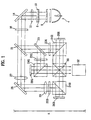
- FIG. 1 illustrates a diagram of an optical system for a liquid crystal projector according to a related art.
- a liquid crystal projector includes first and second fly eye lenses(hereinafter abbreviated FEL) 6 and 8 arranged between a light source 4 and a total reflection mirror 14, a polarizing beam split array(hereinafter abbreviated PBS array) 10, a first light-concentrating lens 12, and a second light-concentrating lens 16 arranged between the total reflection mirror 14 and a first dichroric mirror 18.
- FEL fly eye lenses
- PBS array polarizing beam split array
- first light-concentrating lens 12 polarizing beam split array
- second light-concentrating lens 16 arranged between the total reflection mirror 14 and a first dichroric mirror 18.
- a white light irradiated from a lamp of the light source 4 is reflected by an elliptical mirror so as to proceed toward the first FEL 6.
- the first FEL 6 divides the incident light into cell units so as to be focused on the respective lens cells of the second FEL 8.
- the second FEL 6 transforms the incident light into the parallel light in parallel with a specific part so as to transmit toward the PBS array.
- the PBS array 10 separates the incident light into linear polarized lights having specific optical axes respectively, i.e. a P polarized light and an S polarized light, and a 1/2 wavelength plate(not shown in the drawing) attached to a rear of the PBS array 10 in part transforms the transmitted P polarized light into the S polarized light.
- the incident light is entirely transformed into the S polarized light by the PBS array 10 so that the light irradiated from the light source 4 becomes incident on liquid crystal panels 26R, 26G, and 26B mostly.
- the first light-concentrating lens 12 concentrates the incident light from the PBS array 10 on the total reflection mirror 14, and the total reflection mirror 14 totally reflects the incident light from the first light-concentrating lens 12 so as to make the reflected light proceed toward the second light-concentrating lens 16.
- the second light-concentrating lens 16 concentrates the incident light from the total reflection mirror 14 upon the first dichroric mirror 18.
- the first dichroric mirror 18 transmits a blue area of the incident light as well as reflects green and red areas of the incident light of which wavelengths are longer than that of the blue light.
- the optical system for the liquid crystal projector includes a second dichroric mirror 20 arranged between the first dichroric mirror 18 and the red liquid crystal panel 26R, a first polarizing film 22R, a first polarizing beam split prism(hereinafter abbreviated PBSP) 24R, a second polarizing film 22G and a second PBSP 24G arranged between the second dichroric mirror 20 and the green liquid crystal panel 26G, a first relay lens 27 arranged between the first dichroric mirror 18 and the blue liquid crystal panel 26B, a second total reflection lens 28, a second relay lens 29, a third polarizing film 22B, a third PBSP 24B, a dichroric prism 30 arranged between the first to third PBSPs 24R, 24G, and 24B, and a projecting lens 32 installed to confront a light-projecting surface of the dichroric prism 30.
- PBSP polarizing beam split prism
- the second dichroric mirror 20 reflects a green region light of the incident light reflected on the first dichroric mirror 18 so as to make the reflected green region light proceed toward the second polarizing film 22G and transmits a red region light to proceed toward the first polarizing film 22R.
- the second total reflection mirror 28 reflects an incident blue region light transmitted through the first dichroric mirror 18 to proceed toward the third polarizing film 22B.
- the first and second relay lens 27 and 29 as field lenses relay an imaging point of the blue region light so as to make the imaging point re-imaged on the blue liquid crystal panel 26B.
- the first to third polarizing films 22R, 22G, and 22B transmit just the S polarized lights in parallel with the corresponding optical axes of the polarizing films to make the S polarized lights proceed to the first to third PBSPs 24R, 24G, and 24B, respectively.
- the first to third PBSPs 24R, 24G, and 24B reflect the red, green, and blue S polarized lights, which are transmitted through the first to third polarized films 22R, 22G, and 22B and then become incident, to proceed toward the red, green, and blue liquid crystal panels 26R, 26G, and 26B, respectively.
- the first to third PBSPs 24R, 24G, and 24B acquires image information from the red, green, and blue liquid crystal panels 26R, 26G, and 26B respectively so as to transmit the red, green, and blue lights transformed into the P polarized lights to proceed toward the dichroric prism 30.
- the red, green, and blue liquid crystal panels 26R, 26G, and 26B as reflective type liquid crystal panels transform the incident S polarized lights reflected upon the first to third PBSPs 24R, 24G, and 24B into the P polarized lights respectively in accordance with the image signal, thereby realizing an image.
- the dichroric prism 30 composes the incident red, green, and blue lights by acquiring the image information form the red, green, and blue liquid crystal panels 26R, 26G, and 26B respectively so as to project the composed light through the projecting surface toward the projecting lens 32.
- First and second polarizing transform films are arranged between the first and third PBSPs 24R and 24B and the dichroric prism 30, respectively, so as to transform the P polarized lights into the S polarized lights.
- the dichroric prism 30 reflects red and blue lights of the S polarized light component incident through the first and second polarizing transform films toward the projecting lens 32 as well as transmits the green light of the P polarized light component incident through the second PBSP 24G toward the projecting lens 32, thereby composing an image of red, green, and blue lights.
- the projecting lens 32 magnifies to project the image incident from the dichroric prism 30 on a screen.
- the above-constructed liquid crystal projector according to the related art uses three pieces of liquid crystal panels, thereby requiring a plurality of dichroric mirrors to separate a whit light from a light source into red, green, and blue lights.
- the liquid crystal projector according to the related art uses the reflective type liquid crystal panels, thereby requiring a plurality of polarizing beam split prisms making different paths of the incident/projected lights by taking the reflective type liquid crystal panel as a reference.
- the optical system for such a liquid crystal projector using three pieces of the reflective liquid crystal panels according to the related art requires excessive optical parts so as to increase a size of the optical system. Therefore, there is a limitation to reducing a thickness of the system proportional to the span length of the optical system, thereby having difficulty in providing a slim size.
- the present invention is directed to an optical system for a liquid crystal projector that substantially obviates one or more problems due to limitations and disadvantages of the related art.
- An object of the present invention is to provide an optical system for a liquid crystal projector reducing a number of optical parts as well as a size of the optical system.
- the optical system according to the present invention includes a light source emitting a white light, an illumination part transforming the white light into a predetermined linearly-polarized light and releasing the linearly-polarized light, a first color select transforming to polarize the linearly-polarized light released from the illumination part into another linearly-polarized light in accordance with a wavelength region, and a color resolution/composition part splitting an incident light from the first color select in colors to be incident on the first to third reflective liquid crystal panels respectively and composing the light of which image information is acquired from the first to third liquid crystal panels to release the composed light to a projecting lens system for the enlarging projection, wherein the first to third liquid crystal panels are arranged to confront first to third faces of the color resolution/composition
- the color resolution/composition part comprises first to fourth same-sized blocks bonded one another.
- the first to fourth blocks are bonded to each other using UV rays. More preferably, each of the first to fourth blocks has a triangular cylindrical figure.
- the color resolution/composition part includes a first dichroric coating face coated on a contact face between the first and second blocks to separate a first color light from the incident light from the first color select, a first polarizing beam split coating face coated on a contact face between the second and third blocks to split a transmitted light from the first dichroric coating face into second and third color lights by polarization so as to make the second and third color lights incident on the first and second liquid crystal panels, respectively, the first polarizing beam split coating face making the polarized second and third color lights proceed to the projecting lens system by acquiring image information from the first and second liquid crystal panels, a second polarizing beam split coating face coated on a contact face between the first and fourth blocks to reflect the first color light from the first dichroric coating face to become incident on the third liquid crystal panel, the second polarizing beam split coating face transmitting the first color light of which image information is acquired from the third liquid crystal panel, and a second dichroric coating face coated on a contact face between the third and fourth blocks so as to
- the first and second dichroric coating faces reflect a blue light and transmit green and red lights
- the first and second polarizing beam split coating faces reflect an S-polarized light and transmits a P-polarized light.
- the color resolution/composition part further includes first and second anti-reflection coating faces coated on faces confronting the first color select and the projecting lens system respectively to prevent reflective lights, respectively.
- the color resolution/composition part includes color-transmitting dichroric coating faces coated on faces confronting the first to third liquid crystal panels respectively to transmit the color lights of the corresponding wavelength regions, respectively.
- the optical system further includes a second color select transforming the lights proceeding between the color resolution/composition part and the projecting lens system into a P-polarized light when a P-polarizing screen transmitting the P-polarized light only is used as a screen on which a composed image enlarged/projected by the projecting lens system is Imaged.
- the first and second color selects transforms a green light by polarization and transmits other lights of rest wavelengths intact, the first color select transforms a green S-polarized light into a F-polarized light and transmits red and blue S-polarized lights intact, and the second color select transforms a green S-polarized light into a P-polarized light and transmits red and blue P-polarized lights intact.
- the optical system in an optical system for a liquid crystal projector composing monochromatic images realized in first to third reflective liquid crystal panels respectively for enlarging projection of the composed images, includes a light source emitting a white light, an illumination part transforming the 'white light into a predetermined linearly-polarized light and releasing the linearly-polarized light, a first color select transforming to polarize the linearly-polarized light released from the illumination part into another linearly-polarized light in accordance with a wavelength region, a color resolution/composition part constructed with first to fourth blocks bonded each other and having the same size, the color resolution/composition part splitting an incident light from the first color select in colors to be incident on the first to third reflective liquid crystal panels respectively and composing to release the light of which image information is acquired from the first to third liquid crystal panels, and a second color select transforming the green light of the linearly-polarized lights released from the color resolution/composition part by polarization and transmitting the rest of the lights having other wavelengths
- the color resolution/composition part includes a first dichroric coating face coated on a contact face between the first and second blocks to separate a blue color light from the incident light from the first color select, a first polarizing beam split coating face coated on a contact face between the second and third blocks to split a transmitted light from the first dichroric coating face into red and green color lights by polarization so as to make the red and green color lights incident on the first and second liquid crystal panels, respectively, the first polarizing beam split coating face transmitting and reflecting the polarized red and green color lights by acquiring image information from the first and second liquid crystal panels, a second polarizing beam split coating face coated on a contact face between the first and fourth blocks to reflect the blue color light from the first dichroric coating face to become incident on the third liquid crystal panel, the second polarizing beam split coating face transmitting the blue color light of which image information is acquired from the third liquid crystal panel, and a second dichroric coating face coated on a contact face between the third and fourth blocks so as to transmit the red and
- the first and second dichroric coating faces reflect the blue color light and transmit the green and red color lights.
- the first and second polarizing beam split coating faces reflect an S-polarized light and transmits a P-polarized light.
- the color resolution/composition part further comprising first and second anti-reflection coating faces coated on faces confronting the first color select and the projecting lens system respectively to prevent reflective lights.
- the color resolution/composition part further includes color-transmitting dichroric coating faces coated on faces confronting the first to third liquid crystal panels respectively to transmit the color lights of the corresponding wavelength regions, respectively.
- FIG. 1 illustrates a diagram of an optical system for a liquid crystal projector according to a related art
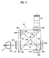
- FIG. 2 illustrates a diagram of an optical system for a liquid crystal projector according to an embodiment of the present invention
- FIG. 3A and FIG. 3B illustrate a process for fabricating a dichroric prism shown in FIG. 2;
- FIG. 4 illustrates a graph of a transmittance characteristic of a first color select shown in FIG. 2.
- FIG. 2 illustrates a diagram of an optical system for a liquid crystal projector according to an embodiment of the present invention.
- an optical system includes three pieces of reflective LCDs 52R, 52G, and 52B, an illumination part constructed with first and second FELs 32A and 32B and a PBS array 34 so as to irradiate a white light from a light source 30 to the LCDs 52R, 52G, and 52B uniformly and effectively, a dichroric prism 40 constructed with four blocks 42, 44, 46, and 48 having different coated surfaces for light composition and resolution, a first color select 38A arranged on a light path between the illumination part and the dichroric prism 40, and a projecting lens 54 arranged at a projecting side of the light composed by the dichroric prism 40, The white light projected from the light source 30 proceeds toward the first FEL 32A.
- the first FEL 32A divides the incident light into cell units to be focused on the respective lens cells of the FEL 32B.
- the second FEL 32B transforms the incident light into the parallel light in parallel with a specific part.
- the PBS array 34 is built in one body with the second FEL 32B so as to separate the incident light into P and S polarized lights having a predetermined optical axis, and a 1/2 wavelength plate(not shown in the drawing) attached to a rear of the PBS array 34 in part transforms the transmitted P polarized light into the S polarized light.
- a first focusing lens 36A concentrates lights. Such an illumination part makes the incident light transformed into the linearly polarized light in one direction, i.e.
- the first color select 38A makes the S polarized light, which is incident from the PBS array 34, polarized selectively in accordance with the corresponding wavelength region. For instance, the first color select 38A rotates a green light at 90° so that the S polarized light is transformed into the P polarized light, while transmitting the red and blue lights with maintaining the S polarization. For such an operation, the first color select 38A, as shown in FIG. 4, has an excellent characteristic - of transmittance for the green light(P polarization) transformed by polarization and the red and blue lights(S polarization) transmitted without polarization.
- the dichroric prism 40 as shown in FIG. 3A and FIG. 3B, is constructed with the four triangular cylindrical blocks 42, 44, 46, and 48 each of which cross-section is triangular.
- FIG. 3A and FIG. 38 illustrate a process for fabricating a dichroric prism shown in FIG. 2.
- first and second dichroric coating faces 42A and 46A are formed at right slant faces of the first and third blocks 42 and 46, respectively.
- first and second polarizing beam split coating faces 44A and 48A are formed at right slant surfaces of the second and fourth blocks 44 and 48. Then, the first to. fourth blocks 42, 44, 46, and 48 prepared separately, as shown in FIG. 3B, are bonded together using UV rays so as to complete the dichroric prism 40.
- the first dichroric coating face 42A coated on the contact face between the first and second blocks 42 and 44 splits the light incident through the first color select 50A.
- the first dichroric coating face 42A reflects the blue S polarized light of the incident light but transmits the red S and green P polarized lights.
- the green P and red S polarized lights having been transmitted through the first dichroric coating face 42A become split at the first polarizing beam split coating face 44A coated on the contact face between the second and third blocks 44 and 46.
- the first polarizing beam split coating face 44A transmits the green P polarized light to proceed to the green LCD panel 52G, and reflects the red S polarized light to proceed to the red LCD panel 52R.
- the first polarizing beam split coating face 44A acquires red image information from the red LCD panel 52R so as to transmit the red P polarized light having been transformed by polarization, and acquires green image information from the green LCD panel 52G to reflect the green S polarized light having been transformed by polarization.
- the blue S polarized light having been reflected upon the first dichroric coating face 42A is reflected on the second polarizing beam split coating face 48A coated on the contact face between the first and fourth blocks 42 and 48 to proceed to the blue LCD panel 52B.
- the second polarizing beam split coating face 48A reflects the incident blue S polarized light reflected on the first dichroric coating face 42A to the blue LCD panel 52B, and acquires blue image information from the blue LCD panel 52B to transmit the blue P polarized light having been transformed by polarization.
- the second dichroric coating face 46A coated on the contact face between the third and fourth blocks 46 and 48 transmits the red P and blue S polarized lights incident from the first polarizing beam split coating face 44A toward the projecting lens 54 as well as reflects the blue P polarized light incident from the second polarizing beam split coating face 48A toward the projecting lens 54.
- each of the red, green, and blue LCD panels 52R, 52G, and 52B as a reflective type LCD panel realizes the corresponding color according to an image signal using the incident light.
- each of the LCD panels 52R, 52G, and 52B transforms a linearly polarized light in one direction into the other linearly polarized light in another direction in accordance with the corresponding image information so as to project the transformed linearly polarized light.
- the projecting lens system 54 magnifies to project the composed image incident from the second dichroric coating face 46A of the prism 40 on a screen.
- the optical system shown in FIG. 2 further includes anti-reflection coating faces 36A and 36B at the dichroric prism 40 confronting the first color select 38A and the projecting lens 54 respectively so as to prevent reflective lights.
- red, green, and blue transmitting filters 50A, 508, and 50C are further formed at portions of the dichroric prism 40 confronting the red, green, and blue LCD panels 52R, 52G, and 52B, respectively, so as to increase color purity.
- Each of the color transmitting filters 50A, 50B, and 50C may further include an anti-reflection material to prevent the reflective light.
- the optical system shown in FIG. 2 further includes a second color select 38B between the dichroric prism 40 and projecting lens 54.
- the second color select 38B P-polarizes the entire light incident on the projecting lens 54.
- the second color select 38B transforms the green S polarized light incident from the dichroric prism 40 into the P polarized light by the rotation of 90°, while transmitting the red and blue P polarized lights as they are.
- a P polarizing screen aligns the polarizing components of the light incident on the projecting lens 50 to the P polarization, and transmits the P polarized lights to a projection screen on which a video magnified by the projecting lens is imaged.
- the P polarizing projection screen absorbs external lights, thereby enabling to improve a contrast.
- the optical system for a liquid crystal projector includes the color select carrying out a polarizing transformation in accordance with a corresponding wavelength and the dichroric prism constructed with the first to fourth blocks bonded to each other and having coating faces of different characteristics, thereby enabling to remarkably reduce the numbers of dichroric mirrors for light split and the PBSs for light composition.
- the optical system for a liquid crystal projector includes the color select and the dichroric prism constructed with a plurality of coating faces of different characteristics, thereby enabling to remarkably reduce the numbers of optical parts for light composition/resolution. Accordingly, the present invention simplifies the optical system, thereby enabling to reduce a cost of production as well as a span length of the optical system.
Landscapes
- Physics & Mathematics (AREA)
- General Physics & Mathematics (AREA)
- Optics & Photonics (AREA)
- Engineering & Computer Science (AREA)
- Multimedia (AREA)
- Signal Processing (AREA)
- Projection Apparatus (AREA)
- Liquid Crystal (AREA)
- Control Of Indicators Other Than Cathode Ray Tubes (AREA)
Abstract
Description
Claims (20)
- Optical system for a liquid crystal projector composing monochromatic images realized in first to third reflective liquid crystal panels respectively for enlarging projection of the composed images, the optical system comprising:wherein the first to third liquid crystal panels are arranged to confront first to third faces of the color resolution/composition part in part, wherein the projecting lens system is arranged to confront a fourth dace of the color resolution/composition part in part, and wherein the first color select is arranged to confront another portion of the same face of the third liquid crystal panel.a light source emitting a white light;an illumination part transforming the white light into a predetermined linearly-polarized light and releasing the linearly-polarized light;a first color select transforming to polarize the linearly-polarized light released from the illumination part into another linearly-polarized light in accordance with a wavelength region; anda color resolution/composition part splitting an incident light from the first color select in colors to be incident on the first to third reflective liquid crystal panels respectively and composing the light of which image information is acquired from the first to third liquidcrystal panels to release the composed light to aprojecting lens system for the enlarging projection,
- The optical system of claim 1, wherein the color resolution/composition part comprises first to fourth same-sized blocks bonded one another.
- The optical system of claim 2, wherein the first to fourth blocks are bonded to each other using UV rays.
- The optical system of claim 2 or 3, wherein each of the first to fourth blocks has a triangular cylindrical figure.
- The optical system of one of claims 2 to 4, the color resolution/composition part comprising:a first dichroric coating face coated on a contact face between the first and second blocks to separate a first color light from the incident light from the first color select;a first polarizing beam split coating face coated on a contact face between the second and third blocks to split a transmitted light from the first dichroric coating face into second and third color lights by polarization so as to make the second and third color lights incident on the first and second liquid crystal panels, respectively, the first polarizing beam split coating face making the polarized second and third color lights proceed to the projecting lens system by acquiring image information from the first and second liquid crystal panels;a second polarizing beam split coating face coated on a contact face between the first and fourth blocks to reflect the first color light from the first dichroric coating face to become incident on the third liquid crystal panel, the second polarizing beam split coating face transmitting the first color light of which image information is acquired from the third liquid crystal panel; anda second dichroric coating face coated on a contact face between the third and fourth blocks so as to transmit the second and third color lights from the first polarizing beam split coating face to the projecting lens system, the second dichroric coating face reflecting the first color light from the second polarizing beam split coating face to the projecting lens system.
- The optical system of claim 5, wherein the first and second dichroric coating faces reflect a blue light and transmit green and red lights.
- The optical system of claim 5 or 6, wherein the first and second polarizing beam split coating faces reflect an S-polarized light and transmits a P-polarized light.
- The optical system of one of claims 2 to 7, the color resolution/composition part further comprising first and second anti-reflection coating faces coated on faces confronting the first color select and the projecting lens system respectively to prevent reflective lights.
- The optical system of one of claims 2 to 8, the color resolution/composition part comprising color-transmitting dichroric coating faces coated on faces confronting the first to third liquid crystal panels respectively to transmit the color lights of the corresponding wavelength regions, respectively.
- The optical system of one of the preceding claims, further comprising a second color select transforming the lights proceeding between the color resolution/composition part and the projecting lens system into a P-polarized light when a P-polarizing screen transmitting the P-polarized light only is used as a screen on which a composed image enlarged/projected by the projecting lens system is imaged.
- The optical system of claim 10, wherein the first and second color selects transforms a green light by polarization and transmits other lights of rest wavelengths intact.
- The optical system of claim 10 or 11, wherein the first color select transforms a green S-polarized light into a P-polarized light and transmits red and blue S-polarized lights intact.
- The optical system of one of claims 10 to 12, wherein the second color select transforms a green S-polarized light into a P-polarized light and transmits red and blue P-polarized lights intact.
- In an optical system for a liquid crystal projector composing monochromatic images realized in first to third reflective liquid crystal panels respectively for enlarging projection of the composed images, the optical system comprising:wherein the first to third liquid crystal panels are arranged to confront first to third faces of the color resolution/composition part in part, wherein the projecting lens system is arranged to confront a fourth dace of the color resolution/composition part in part, and wherein the first color select is arranged to confront another portion of the same face of the third liquid crystal panel.a light source emitting a white light;an illumination part transforming the white light into a predetermined linearly-polarized light and releasing the linearly-polarized light;a first color select transforming to polarize the linearly-polarized light released from the illumination part into another linearly-polarized light in accordance with a wavelength region;a color resolution/composition part constructed with first to fourth blocks bonded each other and having the same size, the color resolution/composition part splitting an incident light from the first color select in colors to be incident on the first to third reflective liquid crystal panels respectively and composing to release the light of which image information is acquired from the first to third liquid crystal panels; anda second color select transforming the green light of the linearly-polarized lights released from the color resolution/composition part by polarization andtransmitting the rest of the lights having other wavelengths so as to release the lights to the projecting lens system for the enlarging projection,
- The optical system of claim 14, the color resolution/composition part comprising:a first dichroric coating face coated on a contact face between the first and second blocks to separate a blue color light from the incident light from the first color select;a first polarizing beam split coating face coated on a contact face between the second and third blocks to split a transmitted light from the first dichroric coating face into red and green color lights by polarization so as to make the red and green color lights incident on the first and second liquid crystal panels, respectively, the first polarizing beam split coating face transmitting andreflecting the polarized red and green color lights by acquiring image information from the first and second liquid crystal panels;a second polarizing beam split coating face coated on a contact face between the first and fourth blocks to reflect the blue color light from the first dichroric coating face to become incident on the third liquid crystal panel, the second polarizing beam split coating face transmitting the blue color light of which image information is acquired from the third liquid crystal panel; anda second dichroric coating face coated on a contact face between the third and fourth blocks so as to transmit the red and green color lights transmitted/reflected through/from the first polarizing beam split coating face to the second color select, the second dichroric coating face reflecting the blue color light transmitted through the second polarizing beam split coating face to the second color select.
- The optical system of claim 15, wherein the first and second dichroric coating faces reflect the blue color light and transmit the green and red color lights.
- The optical system of claim 15, wherein the first and second polarizing beam split coating faces reflect an S-polarized light and transmits a P-polarized light.
- The optical system of one of claims 14 to 17, wherein the color resolution/composition part further comprising first and second anti-reflection coating faces coated on faces confronting the first color select and the projecting lens system respectively to prevent reflective lights.
- The optical system of one of claims 14 to 18, the color resolution/composition part further comprising color-transmitting dichroric coating faces coated on faces confronting the first to third liquid crystal panels respectively to transmit the color lights of the corresponding wavelength regions, respectively.
- In an optical system for a liquid crystal projector composing monochromatic images realized in first to third reflective liquid crystal panels respectively for enlarging projection of the composed images, the optical system comprising:wherein the first to third liquid crystal panels are arranged to confront first to third faces of the color resolution/composition part in part, wherein the projecting lens system is arranged to confront a fourth dace of the color resolution/composition part in part, and wherein the first color select is arranged to confront another portion of the same face of the third liquid crystal panel, anda light source emitting a white light;an illumination part transforming the white light into a predetermined linearly-polarized light and releasing the linearly-polarized light;a first color select transforming to polarize the linearly-polarized light released from the illumination part into another linearly-polarized light in accordance with a wavelength region;a color resolution/composition part constructed with first to fourth blocks bonded each other and having the same size, the color resolution/composition part splitting an incident light from the first color select in colors to be incident on the first to third reflective liquid crystal panels respectively and composing to release the light of which image information is acquired from the first to third liquid crystal panels; anda second color select transforming the linearly-polarized lights released from the color resolution/composition part into other linearly-polarized lights by polarization in accordance with wavelength regions so as to release the lights to the projecting lens system for the enlarging projection,
wherein the color resolution/composition part further comprises:a first dichroric coating face coated on a contact face between the first and second blocks to separate a first color light from the incident light from the first color select;a first polarizing beam split coating face coated on a contact face between the second and third blocks to split a transmitted light from the first dichroric coating face into second and third color lights by polarization so as to make the second and third color lights incident on the first and second liquid crystal panels, respectively, the first polarizing beam split coating face transmitting andreflecting the polarized second and third color lights by acquiring image information from the first and second liquid crystal panels;a second polarizing beam split coating face coated on a contact face between the first and fourth blocks to reflect the first color light from the first dichroric coating face to become incident on the third liquid crystal panel, the second polarizing beam split coating face transmitting the first color light of which image information is acquired from the third liquid crystal panel; anda second dichroric coating face coated on a contact face between the third and fourth blocks so as to transmit the second and third color lights transmitted/reflected through/from the first polarizing beam split coating face to the second color select, the second dichroric coating face reflecting the first color light transmitted through the second polarizing beam split coating face to the second color select.
Applications Claiming Priority (2)
| Application Number | Priority Date | Filing Date | Title |
|---|---|---|---|
| KR2000072708 | 2000-12-02 | ||
| KR10-2000-0072708A KR100381051B1 (en) | 2000-12-02 | 2000-12-02 | Optical System Of Liquid Crystal Projector |
Publications (2)
| Publication Number | Publication Date |
|---|---|
| EP1211547A2 true EP1211547A2 (en) | 2002-06-05 |
| EP1211547A3 EP1211547A3 (en) | 2004-06-02 |
Family
ID=19702602
Family Applications (1)
| Application Number | Title | Priority Date | Filing Date |
|---|---|---|---|
| EP01128628A Withdrawn EP1211547A3 (en) | 2000-12-02 | 2001-11-30 | Optical system for liquid crystal projector |
Country Status (4)
| Country | Link |
|---|---|
| US (1) | US6637891B2 (en) |
| EP (1) | EP1211547A3 (en) |
| KR (1) | KR100381051B1 (en) |
| CN (1) | CN100354690C (en) |
Families Citing this family (12)
| Publication number | Priority date | Publication date | Assignee | Title |
|---|---|---|---|---|
| JP3609715B2 (en) * | 2000-11-27 | 2005-01-12 | 三洋電機株式会社 | Color separation / synthesis device and liquid crystal projector using the same |
| KR100447407B1 (en) * | 2002-01-18 | 2004-09-04 | 엘지전자 주식회사 | Projector |
| US6819365B1 (en) * | 2002-06-05 | 2004-11-16 | Rockwell Collins | Color LCD projector with micro display light engine |
| US7287858B2 (en) | 2003-03-06 | 2007-10-30 | Samsung Electronics Co., Ltd. | Color separating unit and projection type image display apparatus employing the same |
| US20060256289A1 (en) * | 2004-04-30 | 2006-11-16 | Yoshio Fukuzaki | Projection display apparatus |
| DE102004029031B4 (en) * | 2004-06-09 | 2007-07-26 | Decoma (Germany) Gmbh | Hybrid structural component |
| JP4652112B2 (en) * | 2005-04-26 | 2011-03-16 | 富士フイルム株式会社 | Projection display |
| US7497577B2 (en) * | 2005-06-09 | 2009-03-03 | Hewlett-Packard Development Company, L.P. | Light modulator assembly |
| JP2006343632A (en) * | 2005-06-10 | 2006-12-21 | Pentax Corp | Optical system for oblique projection projector |
| US8267521B2 (en) * | 2005-08-31 | 2012-09-18 | Sanyo Electric Co., Ltd. | Optical element, illuminating device, and projection type video display |
| US20120069251A1 (en) * | 2010-09-21 | 2012-03-22 | Shin-Gwo Shiue | Dual panel micro reflective liquid crystal projection device |
| KR102549436B1 (en) * | 2021-04-01 | 2023-06-30 | 롭틱스(주) | Semiconductor circuit pattern inspection device using reflected light and fluorescence |
Family Cites Families (15)
| Publication number | Priority date | Publication date | Assignee | Title |
|---|---|---|---|---|
| CN2287310Y (en) * | 1996-09-03 | 1998-08-05 | 中国大恒公司光电研究所 | Cross flat color light decompounding and compounding device |
| US6101041A (en) * | 1997-05-13 | 2000-08-08 | Nikon Corporation | Cross dichroic prism, method of making the same, and full-color projector using the same |
| JP3459752B2 (en) * | 1997-05-28 | 2003-10-27 | キヤノン株式会社 | Cross dichroic prism and projection display device using the same |
| TW407222B (en) * | 1998-05-14 | 2000-10-01 | Primax Electronics Ltd | The projective display apparatus used to show the image |
| JP2000075245A (en) * | 1998-08-26 | 2000-03-14 | Seiko Epson Corp | Color lcd projector |
| US6113239A (en) * | 1998-09-04 | 2000-09-05 | Sharp Laboratories Of America, Inc. | Projection display system for reflective light valves |
| JP3370010B2 (en) * | 1999-03-31 | 2003-01-27 | 三洋電機株式会社 | LCD projector |
| JP2000292746A (en) * | 1999-04-08 | 2000-10-20 | Hitachi Ltd | Optical block |
| US6995917B1 (en) * | 1999-04-08 | 2006-02-07 | Sharp Laboratories Of America, Inc. | Projection display system using polarized light |
| WO2000063738A1 (en) * | 1999-04-21 | 2000-10-26 | U.S. Precision Lens Incorporated | Optical systems for reflective lcd's |
| US6309071B1 (en) * | 1999-08-04 | 2001-10-30 | Sharp Laboratories Of America, Inc. | Liquid crystal projection display system |
| AU8055301A (en) * | 2000-07-12 | 2002-01-21 | Digital Reflection, Inc. | Method and system for providing prism component assembly |
| EP1350138A4 (en) * | 2000-11-02 | 2007-02-28 | 3M Innovative Properties Co | Optical systems for reflective lcds |
| US6384972B1 (en) * | 2001-06-13 | 2002-05-07 | Prokia Technology Co., Ltd. | Projection display with three polarization beam splitter prisms |
| KR101043620B1 (en) * | 2010-05-04 | 2011-06-22 | 청 장 | Electronic lock device for door with forced release means |
-
2000
- 2000-12-02 KR KR10-2000-0072708A patent/KR100381051B1/en not_active Expired - Fee Related
-
2001
- 2001-11-30 US US09/996,716 patent/US6637891B2/en not_active Expired - Fee Related
- 2001-11-30 EP EP01128628A patent/EP1211547A3/en not_active Withdrawn
- 2001-12-02 CN CNB011381620A patent/CN100354690C/en not_active Expired - Fee Related
Also Published As
| Publication number | Publication date |
|---|---|
| CN100354690C (en) | 2007-12-12 |
| EP1211547A3 (en) | 2004-06-02 |
| US6637891B2 (en) | 2003-10-28 |
| KR20020043666A (en) | 2002-06-12 |
| KR100381051B1 (en) | 2003-04-18 |
| CN1363846A (en) | 2002-08-14 |
| US20020080331A1 (en) | 2002-06-27 |
Similar Documents
| Publication | Publication Date | Title |
|---|---|---|
| EP0646828B1 (en) | Projection type display device | |
| JP3509338B2 (en) | Optical system of reflective LCD projector | |
| KR100364399B1 (en) | Optical System Of Liquid Crystal Projector | |
| JP2000137290A (en) | Illumination device and projection display device using the same | |
| US6637891B2 (en) | Optical system of liquid crystal projector | |
| US6943850B2 (en) | Optical apparatus and projection type display apparatus for reducing a physical distance between a light source and a display | |
| KR100381050B1 (en) | Optical System Of Liquid Crystal Projector | |
| JP2002131750A (en) | Projection display device | |
| US7690793B2 (en) | Illumination optical system and projection-type image display apparatus | |
| US20020003610A1 (en) | Projection type display system using a polarizing beam splitter | |
| JP3639842B2 (en) | Projection display | |
| US20040207769A1 (en) | Projection display device | |
| CN100520567C (en) | Projector | |
| KR0184364B1 (en) | 3d image projector using optical reflective modulator | |
| JP2002090874A (en) | Optical device and projection display device using the same | |
| US20020097347A1 (en) | Transmission-type liquid crystal projection display | |
| JP2768345B2 (en) | LCD projector | |
| KR100342829B1 (en) | Optical System Of Liquid Crystal Projector | |
| KR100342830B1 (en) | Optical System Of Liquid Crystal Projector | |
| KR100744503B1 (en) | Optical system of LCD projector | |
| KR100385878B1 (en) | Optical System Of Liquid Crystal Projector using Kaster Prism | |
| JPH0527203A (en) | Polarization synthesizing element and liquid crystal display device using the same | |
| KR20010010329A (en) | Optical Device Of Liquid Crystal Projector | |
| JPH11352443A (en) | Video display device | |
| JP2004264663A (en) | Reflective LCD projector |
Legal Events
| Date | Code | Title | Description |
|---|---|---|---|
| PUAI | Public reference made under article 153(3) epc to a published international application that has entered the european phase |
Free format text: ORIGINAL CODE: 0009012 |
|
| AK | Designated contracting states |
Kind code of ref document: A2 Designated state(s): AT BE CH CY DE DK ES FI FR GB GR IE IT LI LU MC NL PT SE TR |
|
| AX | Request for extension of the european patent |
Free format text: AL;LT;LV;MK;RO;SI |
|
| PUAL | Search report despatched |
Free format text: ORIGINAL CODE: 0009013 |
|
| AK | Designated contracting states |
Kind code of ref document: A3 Designated state(s): AT BE CH CY DE DK ES FI FR GB GR IE IT LI LU MC NL PT SE TR |
|
| AX | Request for extension of the european patent |
Extension state: AL LT LV MK RO SI |
|
| 17P | Request for examination filed |
Effective date: 20041111 |
|
| AKX | Designation fees paid |
Designated state(s): DE FR GB NL |
|
| RBV | Designated contracting states (corrected) |
Designated state(s): DE FR GB NL |
|
| 17Q | First examination report despatched |
Effective date: 20050920 |
|
| STAA | Information on the status of an ep patent application or granted ep patent |
Free format text: STATUS: THE APPLICATION IS DEEMED TO BE WITHDRAWN |
|
| 18D | Application deemed to be withdrawn |
Effective date: 20090116 |