EP1211486A2 - Magnetostrictive sensor - Google Patents
Magnetostrictive sensor Download PDFInfo
- Publication number
- EP1211486A2 EP1211486A2 EP01000673A EP01000673A EP1211486A2 EP 1211486 A2 EP1211486 A2 EP 1211486A2 EP 01000673 A EP01000673 A EP 01000673A EP 01000673 A EP01000673 A EP 01000673A EP 1211486 A2 EP1211486 A2 EP 1211486A2
- Authority
- EP
- European Patent Office
- Prior art keywords
- valve
- conduit
- sensor
- sonic
- sonic wave
- Prior art date
- Legal status (The legal status is an assumption and is not a legal conclusion. Google has not performed a legal analysis and makes no representation as to the accuracy of the status listed.)
- Withdrawn
Links
Images




Classifications
-
- G—PHYSICS
- G01—MEASURING; TESTING
- G01D—MEASURING NOT SPECIALLY ADAPTED FOR A SPECIFIC VARIABLE; ARRANGEMENTS FOR MEASURING TWO OR MORE VARIABLES NOT COVERED IN A SINGLE OTHER SUBCLASS; TARIFF METERING APPARATUS; MEASURING OR TESTING NOT OTHERWISE PROVIDED FOR
- G01D5/00—Mechanical means for transferring the output of a sensing member; Means for converting the output of a sensing member to another variable where the form or nature of the sensing member does not constrain the means for converting; Transducers not specially adapted for a specific variable
- G01D5/48—Mechanical means for transferring the output of a sensing member; Means for converting the output of a sensing member to another variable where the form or nature of the sensing member does not constrain the means for converting; Transducers not specially adapted for a specific variable using wave or particle radiation means
- G01D5/485—Mechanical means for transferring the output of a sensing member; Means for converting the output of a sensing member to another variable where the form or nature of the sensing member does not constrain the means for converting; Transducers not specially adapted for a specific variable using wave or particle radiation means using magnetostrictive devices
Definitions
- This invention relates to a position sensor, and particularly, to a magneto-strictive sensor for determining the position of a valve in an internal combustion engine.
- Automotive manufacturers are currently utilizing camless intake and exhaust valve assemblies to control fluid communication in engine cylinders of internal combustion engines.
- the camless valve assemblies may utilize hydraulic, pneumatic, or electromechanical means to move a valve.
- valve dwell time i.e., the time interval a valve is open
- valve dwell position i.e., the amount the valve is open
- valve opening rate i.e., a valve closing rate
- initial opening time of a valve i.e., valve phasing
- valve assemblies may be independently actuated or controlled with respect to other valve assemblies in an engine.
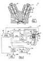
- FIG. 1 a known engine 10 having an engine head 12 and electromechanical valve assemblies 14, 16 is shown.
- the engine head 12 includes an air intake line 18 and an exhaust line 20.
- valve assemblies 14, 16 control communication between the line 18, 20 respectively, with an engine cylinder (not shown).
- the valve assembly 14 includes a pair of solenoids 22, 24, and a valve 26 having a valve stem 28 and a valve head 30.
- the solenoids 22, 24 are utilized to either open or close the valve 26.
- the solenoid 24 is energized (and solenoid 22 is de-energized)
- the valve head 30 is moved axially away from a valve seat 32 to allow fluid communication between the intake line 18 and a cylinder (not shown).
- valve head 30 engages the valve seat 32 to prevent fluid communication between the intake line 18 and the cylinder.
- the known valve assembly 14 has a two-position valve 26 having either a full open state or a full closed state.
- valve assembly 14 has several operational disadvantages.
- valve assembly 14 cannot precisely control a valve dwell time duration, a valve dwell position, a valve opening rate, a valve closing rate, valve phasing.
- valve assembly 14 cannot be utilized to effectively increase fuel efficiency and lower emissions in an engine.
- valve assembly 14 does not provide for soft seating of the valve head 30 on the valve seat 32 under all operating conditions of the engine 10 including temperature extremes and control strategy variations.
- valve head 30 generates undesirable noise when contacting the valve seat 32.
- Another known electromechanical valve assembly (not shown) includes an electric motor, a cam, and a poppet valve.
- the motor selectively rotates an output shaft that is connected to the cam.
- the cam converts that rotary motion of the output shaft to an axial motion of the poppet valve.
- This known valve assembly is capable of controlling a valve dwell time, a valve dwell position, a valve opening rate, and a valve closing rate.
- valve assembly requires a separate cam resulting in increased component and manufacturing costs.
- valve assembly requires a relatively large package space since a separate cam is utilized for each poppet valve.
- Position sensors have been used to determine an axial position of valves in intake and exhaust valve assemblies.
- Each valve assembly may have a corresponding position sensor disposed on top of the valve assembly.
- the known position sensors have several disadvantages in an automotive vehicle.
- the known position sensors have a relatively thick axial profile.
- the sensors substantially increase the height of intake and exhaust valve assemblies, resulting in an increased height of a vehicle hood to accommodate the valve assemblies.
- magneto-strictive sensor for determining a position of a moving object having a magnet associated therewith characterised in that the sensor comprises a sonic conduit associated with the object, a sonic wave generator generating a sonic wave in said conduit responsive to a transmit signal, said sonic wave propagating to a localized stress boundary in said conduit, said boundary being induced by said magnet, said sonic wave being reflected in said conduit from said boundary, a sonic wave receiver receiving said reflected sonic wave from said conduit and generating a received signal responsive to said sonic wave and a sensor controller configured to generate said transmit signal and to receive said received signal, said controller calculating a position value responsive to a travel time of said sonic wave in said conduit.
- the sensor may be adapted for determining a rotational position of the object, the object rotating about a first axis and having a magnet rotating therewith and the sonic conduit extending around a portion of the circumference of the object.
- the position value may be a rotational position value
- the sonic conduit may include an arcuate shaped portion disposed proximate to an outer surface of said object.
- the senor may be adapted for determining an axial position of an object moving along a first axis, wherein a magnet is disposed proximate said object and is stationary with respect to said first axis and the sonic conduit extends generally axially on or integral with said object.
- the position value may be an axial position value.
- the sonic conduit may comprise an axially extending bar or wire.
- the sonic conduit may be constructed from a nickel-iron alloy.
- the sonic wave generator and said sonic wave receiver may be piezoelectric transducers.
- the sensor may further comprise an oscillator operatively connected between said sensor controller and said sonic wave generator, said oscillator generating an oscillator signal responsive to said transmit signal.
- the sensor further may comprise a temperature sensor connected to the sensor controller, said temperature sensor generating a temperature signal indicative of a temperature of said sonic conduit.
- a method for determining a rotational position of an object moving relative to a first axis said object having a magnet associated therewith, wherein the method comprises the steps of providing a sonic conduit extending along a portion of the object, generating a sonic wave in said conduit that propagates to a localized stress boundary in said conduit, said localized stress boundary being induced by said magnet, the sonic wave being reflected in said conduit from said boundary, receiving said reflected sonic wave at predetermined position along said conduit and calculating a position value responsive to a travel time of said sonic wave in said conduit.
- the step of generating a sonic wave may include the substeps of generating a transmit signal, generating an oscillator signal responsive to said transmit signal and generating a vibration in said sonic conduit responsive to said oscillator signal.
- the object may be rotating about the first axis and the magnet may be rotating with the object and a rotational position value responsive to a travel time of the sonic wave in the conduit is calculated.
- the position value is further calculated responsive to a velocity of said sonic wave in said sonic conduit and a radius of said sonic conduit.
- the object may be moving axially along a first axis and the magnet may be disposed stationary with respect to said first axis and an axial position value responsive to a travel time of said sonic wave in said conduit is calculated.
- the axial position value may be further calculated responsive to a velocity of said sonic wave in said sonic conduit and a length of said conduit.
- Figure 2 illustrates an automotive vehicle 34 having an engine 36, an engine control system 38, and a power distribution system 40.
- the engine 36 is an internal combustion engine and includes an engine head 42, an engine block 44, electromechanical valve assemblies 46, 48, a cylinder 50, a fuel injector 52, a spark plug 54, a piston 56, a connecting rod 58, and a crankshaft 60.
- the engine 36 includes a plurality of cylinders 50, each cylinder 50 having valve assemblies 46, 48, fuel injector 52, spark plug 54, piston 56, and connecting rod 58.
- the engine head 42 is conventional in the art and defines an intake line 62 and a exhaust line 64.
- the engine head 42 is mounted to the engine block 44 and is configured to hold the valve assemblies 46, 48, the spark plug 54, and the fuel injector 52.
- the engine block 44 is conventional in the art and defines each of the cylinders 50.
- the engine block 44 is configured to receive the engine head 42.
- the electromechanical valve assemblies 46, 48 comprise an intake valve assembly and an exhaust valve assembly respectively.
- the valve assembly 46 controls fluid communication between the intake line 62 and the cylinder 50.
- the valve assembly 48 controls fluid communication of exhaust gases between the cylinder 50 and the exhaust line 64.
- valve assemblies 46, 48 are substantially similar with the only difference being valve assembly 46 having a larger valve face surface than valve assembly 48 only the valve assembly 46 will be described in detail hereinafter.
- valve assembly 46 Before describing the various components of the electromechanical valve assembly 46, the operational advantages of the valve assembly 46 will be discussed.
- valve assembly 46 has a valve 70 that may be selectively moved to commanded incremental axial positions (discussed in greater detail below), the valve assembly 46 provides for the precise control of several valve operational parameters.
- valve operational profiles 86, 88, 90, 92 showing the various operational parameters that may be incrementally varied by the valve 70 are shown.
- valve assembly 46 can selectively vary the opening rate of valve 70.
- profiles 86, 90 illustrate two different possible opening rates OR1 and OR2 for the valve 70.
- valve assembly 46 can selectively vary the closing rate of the valve 70.
- profiles 86, 90 illustrate two different possible closing rates CR1 and CR2 for the valve 70.
- valve assembly 46 can selectively vary the opening rate of the valve 70 independent of the closing rate of the valve 70, and vice versa, as shown in profile 90.
- valve 70 and the rotor 68 limits the valve opening and closing slew rates.
- the assembly 46 may further selectively vary the dwell time of the valve 70.
- profiles 86, 88 illustrate two possible dwell times ⁇ T1 and ⁇ T2, respectively, for the valve 70.
- the assembly 46 can further move the valve 70 to a desired dwell position other than a full open position as shown in profile 92.
- the valve assembly 46 includes a stator 66, a rotor 68, a valve 70, bearings 72, 74, an enclosure 76, a centralising spring 78, a sensor magnet 80, and a position sensor 82.
- the stator 66 is provided to produce a torque to cause rotation of the rotor 68.
- the stator 66 and rotor 68 are configured as a brushless DC motor.
- stator 66 and rotor 68 could be configured as a switch reluctance motor or other motor configurations well known to those skilled in the art.
- stator 66 is constructed from a plurality of laminated plates 94 stacked adjacent one another.
- stator 66 has a central bore 96 extending axially therethrough configured to receive the rotor 68.
- the illustrated stator 66 and rotor 68 comprise a three-phase (i.e., phases A, B, C) two-pole, brushless DC motor.
- stator windings 98 may be routed in the stator slots S1-S12 to define the phases A, B, C.
- stator 66 and rotor 68 could alternately be constructed as a three-phase, four-pole brushless DC motor.
- stator 66 and rotor 68 could have a higher number of poles if desired.
- the rotor 68 is provided to drive the valve 70 in a first and a second axial direction.
- the rotor 68 includes a ring magnet 100 and a ballnut 102.
- the ring magnet 100 may comprise magnet segments 104, 106, or may alternately comprise a single unitary magnet.
- the number of magnet segments of the magnet 100 is equal to the number of poles of the stator 66.
- each magnet segment has a flat inner surface that rests against a corresponding facet defined by an outer surface of the ballnut 102.
- the ring magnet 100 is fixedly attached around the ballnut 102 and may be glued to the ballnut 102.
- the ballnut 102 is provided to engage and drive the valve 70.
- the ballnut 102 is conventional in the art and may be constructed from a plurality of ferromagnetic materials including steel or iron.
- the ballnut 102 includes a cylindrical body portion 108 and mounting arms 110, 112.
- the cylindrical body portion 108 has a central bore 114 configured to receive the valve 70 therein.
- the body portion 108 has a helical groove 116 separated by a land portion 118.
- the body portion 108 further includes a return channel 120 for recirculating a train of abutting load ball bearings 122 that travel in the groove portions 116.
- the return channel 120 may comprise an internal U-shaped channel machined within the body portion 108.
- the mounting arms 110, 112 are provided to rotatably support the rotor 68 about an axis 122.
- the mounting arm 110 is attached to a lower end of the ballnut 102 and is further attached to the bearing 72.
- the mounting arm 112 is attached to an upper end of the ballnut 102 and is further attached to the bearing 74.
- the rotor 68 may rotate in either a clockwise or counter-clockwise direction about the axis 122.
- the valve 70 is provided to selectively engage or disengage a valve seat 124.
- the valve 70 may be constructed from a plurality of materials including, for example, case hardened steel or ceramics such aluminum nitride.
- the material used for constructing the valve 70 preferably has a relatively low mass so that the valve 70 may be easily accelerated.
- the valve 70 includes a valve stem 126, a valve head 84, and an anti-twist guide 128.
- the valve stem 126 has a helical groove 130 that is separated by a land portion 132.
- the helical groove 130 has the same pitch as the helical groove 116 of the ballnut 102.
- the helical grooves 116, 130 form a raceway between the rotor 68 and the valve 70.
- the ball bearings 122 Upon rotation of the rotor 68, the ball bearings 122 travel in the helical grooves 116, 130 and are recirculated in the raceway by the return channel 120.
- the helical groove 130 of the valve stem 126 has a thread or groove pitch P.
- the thread pitch P is set equal to a maximum valve stroke ZMAX.
- valve 70 and the rotor 68 multiple rotations of the rotor 68 may be utilized to move the valve 70 to a maximum valve stroke ZMAX.
- the valve stroke ZMAX is typically 8 mm, although the valve assembly 46 may be configured to have a valve stroke greater than or less than 8 mm.
- valve stem 126 may be inserted through an aperture 123 in the engine head 42.
- the rotor 68 may have a cylindrical cardboard section (not shown) disposed in the bore 114.
- the cardboard section is utilized to hold the ball bearings 122 in the return channel 120 prior to attaching the rotor 68 to the valve stem 126.
- valve stem 126 During attachment of the valve stem 126 to the rotor 68, the rotor 68 is threadably received by the valve stem 126, which forces the cardboard section out of the bore 114.
- the ball bearings 122 travel in the raceway defined by the grooves 116 and 130.
- the body portion 108 of the rotor 68 may include a second helical groove (not shown) extending alongside groove 116.
- valve stem 126 of the valve 70 may include a second helical groove (not shown) extending alongside the groove 130.
- the two additional helical grooves form a second raceway (not shown) for a second set of ball bearings to travel therein.
- the second set of ball bearings are recirculated in the second raceway via a second return channel (not shown).
- valve 70 By utilizing a second set of recirculating ball bearings, the effect of side loading forces on the valve 70 may be reduced.
- the spring 78 is provided to centralise the valve 70 at a predetermined axial position when the engine 36 is shutdown (and the stator 66 is de-energized).
- This initial reference position may be measured by a position sensor and may be stored by a valve controller 134 for calculating the relative position of the valve 70 with respect to the initial position.
- the spring 78 is connected between one end of the valve stem 126 and the enclosure 76.
- the spring 78 may be selected to centralise the valve 70 at any desired initial between the 0 valve position and the ZMAX valve position.
- each of the springs 78 may be pre-loaded to each valve 70 in a closed position (i.e., 0 valve position) to minimize a cranking torque of an integrated starter/alternator of the engine 36.
- valve head 84 is configured to engage the valve seat 124 of the engine 36.
- valve head 84 may be integrally connected to the valve stem 126.
- the anti-twist guide 128 is provided to prevent rotational movement of the valve 70 about the axis 122.
- the anti-twist guide 128 may comprise a radially extending engagement portion connected to the valve stem 126 that engages a slot or keyway (not shown) in the engine head 42.
- valve 70 will less likely deteriorate the valve seat 124 if the valve 70 does not rotate while engaging the valve seat 124.
- the axial position of the valve 70 may be accurately determined if the valve 70 does not rotate relative to the rotation of the rotor 68.
- the bearings 72, 74 are provided to allow rotation of rotor 68 relative to the stator 66 and are conventional in the art.
- the bearing 74 is connected between a mounting arm 112 of the rotor 68 and an upper mounting arm 136 of the enclosure 76.
- the bearing 72 is connected between the mounting arm 110 of the rotor 68 and a lower mounting arm 138 of the enclosure 76.
- the enclosure 76 is provided to enclose and protect the stator 66, the rotor 68, and portions of the valve 70.
- the enclosure 76 is mounted to the engine head 42.
- the enclosure 76 includes an outer wall 140, an upper mounting arm 136, and a lower mounting arm 138.
- the outer wall 140 defines a bore 142 for the valve stem 126 to extend therethrough.
- the sensor magnet 80 is provided to indicate the rotational position of the rotor 68.
- the magnet 80 may be connected to a mounting arm 112 of the rotor 68.
- the position sensor 82 is provided to determine the rotational position ⁇ M of the rotor 68 and an axial position Z of the valve 70 in accordance with the present invention.
- the position sensor 82 may comprise a magneto-strictive sensor that has a relatively small package space as compared with conventional position sensors.
- the magneto-strictive sensor 82 includes a sonic conduit 144, a sensor controller 146, an oscillator 148, a sonic wave generator 150, a sonic wave receiver 152, and a temperature sensor 154.
- the sensor controller 146 is provided to calculate a rotational position ⁇ M of the rotor 68 and an axial position Z of the valve 70.
- the controller 146 may comprise either discrete circuits or a programmable microcontroller.
- the sensor controller 146 is electrically connected to the oscillator 148, the sonic wave receiver 152, and the temperature sensor 154.
- the sensor controller 146 is configured to generate a transmit signal V TR at a predetermined frequency that is transmitted to the oscillator 148.
- the transmit signal V TR is transmitted at a frequency of 100 Khz.
- the sensor controller 146 receives the temperature signal VTEMP, the received signal VR (explained in detail hereinafter) and the oscillator signal V OSC (explained in detail hereinafter) and calculates the rotational position ⁇ M of the rotor 68 and an axial position Z of the valve 70.
- the oscillator 148 is provided to generate an oscillator signal V OSC responsive to the transmit signal V TR .
- the oscillator 148 may comprise a conventional voltage controlled oscillator or discrete circuits.
- the oscillator 148 is electrically connected in series between the sensor controller 146 and the sonic wave generator 150.
- the oscillator 148 receives a transmit signal V TR at a high logic level and generates an oscillator signal V OSC at a 1 Mhz frequency responsive thereto.
- the frequency of the transmit signal V TR and the oscillator signal V OSC may be greater than or less than 100 Khz or 1Mhz, respectively, depending upon the desired accuracy of the calculated rotational position ⁇ M and the axial position Z.
- the frequency of the transmit signal V TR is preferably greater than twice the round trip travel time T RT (explained in greater detail below) of the sonic wave.
- the sonic wave generator 150 is provided to generate a sonic wave in the sonic conduit 144.
- the sonic wave generator 150 may comprise a conventional piezoelectric transducer and is electrically connected to the oscillator 148 and is further bonded to the sonic conduit 144.
- the generator 150 receives the oscillator V OSC and generates a sonic wave (i.e., sound wave) in the conduit 144 responsive to the oscillator signal V OSC .
- the sonic conduit 144 is provided to propagate a sonic wave in the conduit 144 around a portion of a circumference of the rotor 68.
- the sonic conduit 144 may comprise a metal wire or a metal strip that extends around a substantial portion of the circumference of the rotor 68 proximate to the rotor 68.
- the conduit 144 may be constructed from a plurality of metals, including for example, a nickel-iron alloy and may be constructed of 18 gauge wire.
- the sensor magnet 80 disposed on the rotor 68 induces a localized stress boundary 156 on the conduit 144 proximate to the magnet 80.
- the magnet 80 deforms the conduit 144.
- the magnet 80 and the boundary 156 are indicative of the position of the rotor 68.
- a sonic wave travelling in the conduit 144 in a first direction to the stress boundary 156 will be reflected from the boundary 156 in a second direction (opposite the first direction).
- the gap G in the conduit 144 ensures that each the sonic wave initially propagates in only one direction (i.e., clockwise in Figure 8) around the conduit 144 to the boundary 156.
- the sonic wave receiver 152 is provided to generate a received signal VR upon receipt of a sonic wave.
- the sonic wave receiver 152 may comprise a conventional piezoelectric transducer and is electrically connected to the sensor controller 146 and is further connected to the conduit 144.
- the receiver 152 receives the sonic wave and generates the received signal VR responsive thereto.
- the temperature sensor 154 generates a temperature signal VTEMP indicative of the ambient air temperature around the sonic conduit 144 and valve assembly 46.
- the temperature sensor 154 is conventional in the art and is electrically connected to the sensor controller 146.
- the method includes a step 158 of providing a sonic conduit 144 extending around a substantial portion of a circumference of the rotor 68.
- the method further includes a step 160 of generating a sonic wave in the conduit 144 that propagates to a localized stress boundary 156 in the conduit 144 wherein the sonic wave is reflected in the conduit 144 from the boundary 156.
- the sensor controller 146 between the time interval T0-T1, generates a transmit signal V TR at high logic level that causes the oscillator 148 to generate oscillator signals VOSC.
- the oscillator signals V OSC cause the sonic wave generator 150 to generate a sonic wave (i.e., vibration) in the conduit 144.
- the sonic wave propagates in a first direction to the stress boundary 156 and is reflected from the stress boundary 156 in a second direction (opposite the first direction) back toward a sonic wave receiver 152.
- the method further includes a step 162 of receiving the reflected sonic wave at a predetermined position along the sonic conduit 144.
- the sonic wave is received by the sonic wave receiver 152.
- the receiver 152 In response, the receiver 152 generates the received signal VR that is transmitted to the sensor controller 146.
- the method further includes a step 164 of calculating a rotational position value ⁇ M of the rotor 68 and an axial position Z of the valve 70 responsive to the round trip travel time T RT of the sonic wave in the conduit 144.
- conduit length from point P1 to point P2 is assumed to be zero.
- the velocity of the sonic wave is dependent on the temperature of the conduit 144.
- VEL(T) VEL0[1 + ⁇ (T-T 0 )];
- the foregoing equation for calculating VEL(T) represents a truncated Fourier expansion of non-linear velocity versus temperature relationship.
- an electromechanical valve assembly 166 is provided that is a second embodiment of the valve 46.
- valve assembly 166 is substantially the same as the valve assembly 46, except that the sensor magnet 80 has been removed and a valve 168 and a position sensor 170 are used instead of valve 70 and position sensor 82, respectively.
- the valve 168 is substantially the same as the valve 70 except that a valve 168 has a bore 172 extending axially into the valve 168.
- the position sensor 170 is provided to calculate an axial position Z of the valve 168.
- the position sensor 170 is substantially the same as the position sensor 82 and includes the sensor controller 146, the oscillator 148, the sonic wave generator 150, the sonic wave receiver 152, and the temperature sensor 154.
- the position sensor 170 utilizes a flexible lead wire 174 and a sonic conduit 176 instead of the sonic conduit 144.
- the sonic conduit 176 may comprise a longitudinally extending metal wire or a metal bar that is disposed in the bore 172 of the valve 168.
- the conduit 176 may be constructed from a plurality of metals, including for example, a nickel-iron alloy.
- the ring magnet 100 of the rotor 68 induces a localized stress boundary 178 in the conduit 176.
- the axial distance D from a first end of the conduit 176 to the stress boundary 178 is indicative of the axial position of the valve 168.
- valve 168 will increase as valve 168 incrementally moves in a first axial direction (downward in Figure 13).
- the distance D (and the round trip travel time T RT of the sonic wave) will decrease as the valve 168 moves in a second axial direction (upward in Figure 13) opposite the first axial direction.
- the length of the lead wire 174 is assumed to be equal to a zero length. Referring to Figure 14, a method for determining an axial position of a valve 168 utilizing the position sensor 170, will be described.
- the method includes a step 180 of providing a sonic conduit 176 extending generally axially on or integral with the valve 168.
- the method further includes a step 182 of generating a sonic wave in the conduit 176 that propagates to a localized stress boundary 178 wherein the wave is reflected from the boundary 178.
- the method further includes a step 184 of receiving the reflected sonic wave at a predetermined position along the conduit 176.
- the method includes a step 186 of calculating an axial position Z of the valve 168 responsive to the travel time of the sonic wave in the conduit 176.
- the engine 36 includes the fuel injector 52.
- the fuel injector 52 selectively provides fuel to one or more cylinders 50 and is conventional in the art.
- each fuel injector 52 delivers a predetermined amount of fuel into one or more cylinders 50 responsive to a fuel injector control signal V FI generated by an engine controller 188.
- the spark plug 54 is provided to ignite the fuel in the cylinder 50 responsive to an ignition control signal V I generated by the engine controller 188.
- the piston 56 drives the crankshaft 60 via the connecting rod 58.
- the engine control system 38 is provided to control the operation of the engine 36 in accordance with the present invention.
- the engine control system 38 includes a valve controller 134, an engine controller 188, a crankshaft position sensor 190, and the valve position sensor 82.
- the valve controller 134 is a bi-directional controller that can control the incremental movement of valves in both axial directions.
- each of the valve assemblies 46, 48 includes a valve 70 and a position sensor 82.
- valve controller 134 receives a rotational position value ⁇ M and an axial position value Z from the position sensor 82, and a crankshaft position signal V CS from the crankshaft position sensor 190.
- valve controller 134 receives operational parameters from the engine controller 188 for each valve 70 via a communication bus 192.
- the communication bus may comprise a CAN (i.e., controller area network) bus operating at a bus speed of 1 megabit/second.
- CAN i.e., controller area network
- the valve operational parameters include a valve dwell time, a valve opening rate,
- valve controller 134 In response to the foregoing signals and parameters for each valve 70, the valve controller 134 generates a commanded valve position current I CP for each valve assembly 46, 48 to selectively control the axial position of each valve 70.
- valve controller 134 a more detailed schematic of the valve controller 134 is illustrated.
- valve controller 134 contains a conventional commutation circuit 194 for each valve assembly 46, 48 in the engine 36.
- valve controller 134 would have eight commutation circuits 194 to control the eight valve assemblies.
- Each of the circuits 194 would be connected between a node 196 (connected to a positive terminal of the battery 234) and system ground.
- Each commutation circuit 194 includes switches 198, 200, 202, 204, 206, 208, a capacitor 210, a resistor 212, and a commutation module 214.
- Switches 198, 200, 202, 204, 206, 208 are provided to selectively energize the phases A, B, C of the stator 66.
- Switches 198, 200, 202, 204, 206, 208 are conventional in the art and may comprise either MOSFET transistors, IGBT transistors in either planar or trench structure, or bipolar transistors.
- Switches 198, 200 are connected in series between nodes 196, 216 and have an intermediate node 218 connected to phase A.
- switches 202, 204 are connected in series between nodes 196, 216 and have an intermediate node 220 connected to phase B.
- switches 206, 208 are connected in series between nodes 196, 216 and have an intermediate node 222 connected to phase C.
- the capacitor 210 is provided to ground transient voltage spikes which could damage the switches 198, 200, 202, 204, 206, 208.
- the capacitor 210 is connected between the node 196 and ground.
- the resistor 212 is provided to sense the current flow through the switches 198, 200, 202, 204, 206, 208 and to prevent damage thereto.
- the resistor 212 is connected between the node 216 and ground.
- the commutation module 214 is provided to generate control signals to control the energisation of the phases A, B, C of the stator 66.
- the commutation module 214 receives either the rotational position value ⁇ M or the axial position Z from the position sensor 82. In response, the commutation module generates commutation signals CS1, CS2, CS3, CS4, CS5, CS6 to selectively energize the phases A, B, C.
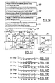
- commutation signals CS1, CS2, CS3, CS4, CS5, CS6 are shown for energizing the phases A, B, C pairwise to move the rotor 68 one complete revolution (i.e., 360 mechanical degrees) are shown.
- valve operational profile 215 (illustrating a complete operational cycle of a valve 70) and a corresponding commanded valve position current ICP effectuating the valve cycle is shown.
- Figure 17A illustrates the pressure P within a cylinder 50 as the valve 70 progresses through the valve cycle.
- valve controller 134 commands the valve 70 to move to an open position to allow exhaust gases in the cylinder 50 to exit the cylinder 50.
- valve controller 134 increases the commanded valve position current ICP in a positive direction that results in the valve accelerating toward a full open position.
- valve controller 134 decreases the commanded position current ICP.
- valve 70 When the current ICP reverses direction as a negative or braking current, the valve 70 de-accelerates prior to reaching the full open position.
- the controller 134 maintains the positive current ICP at an dwell current level for a desired dwell time.
- the holding current is necessary to counteract forces acting the valve 70 generated by the spring 78 and the cylinder gas pressure.
- valve 70 is maintained at a full open position.
- the cylinder pressure remains at a relatively constant pressure level.
- the controller 134 commands the valve 70 to move to a closed position.
- the controller 134 decreases the current ICP until it reverses direction as a negative current.
- valve 70 accelerates toward a full closed position.
- the controller 134 decreases negative current ICP until it reverses direction as a positive current to de-accelerate the valve 70 prior to the valve 70 reaching the full closed position.
- the de-acceleration of the valve 70 provides for soft seating of the valve 70 with the valve seat 124.
- engine noise may be reduced.
- the engine controller 188 is provided to control the operation of the engine 36.
- the engine controller 188 may comprise either discrete circuits or a programmable microcontroller.
- the controller 188 receives a crankshaft position signal VCS and generates the fuel injector control signal VFI responsive thereto.
- controller 188 also calculates valve operational parameters for each valve including a dwell time duration, an opening rate, a closing rate, a dwell position, and phasing information.
- controller 188 transmits these operational parameters to the valve controller 134 via a communication bus 192.
- the crankshaft position sensor 190 generates a crankshaft position signal VCS indicative of the rotational position of the crankshaft 60.
- the sensor 190 is conventional in the art and may comprise a Hall Effect Sensor or a variable reluctance sensor.
- the engine controller 188 may receive the crankshaft position signal VCS and derive the crankshaft angle ⁇ CS responsive thereto.
- the method utilizes a braking current generated when a valve is closing in the exhaust valve assembly 48 as an accelerating current to open a valve in the intake valve assembly 46.
- the method for current recirculation includes a step 224 of providing an exhaust valve assembly 48 having stator phases D and E selectively connected between a node 196 and ground.
- the method further includes a step 226 of providing an intake valve assembly 46 having stator phases A and B selectively connected between node 196 and ground.
- the method further includes a step 228 of generating a braking current ICP in phases D and E of the exhaust valve assembly 48.
- the exhaust valve assembly 48 is closing a valve and is generating a braking current ICP (i.e., a negative current).
- valve assembly 48 when the phases D and E of valve assembly 48 are generating a negative current ICP (i.e., -ICP), the current flows through the node 196 common to all commutation circuits 194.
- ICP negative current
- the method further includes a step 230 of connecting the stator phases A, B of the intake valve assembly 46 to the node 196 to direct the braking current ICP into stator phases A, B as an accelerating current ICP.
- the intake valve assembly 46 utilizes the braking current ICP generated by the exhaust valve assembly 48 to open the valve 70.
- a power distribution system 40 is provided for the engine control system 38 and the engine 36.
- the power distribution system 40 includes an alternator 232, a battery 234, a battery 236, and a DC/DC converter 238.
- the alternator 232 is provided to maintain the state of charge in the battery 234 and the battery 236 at an adequate operational level.
- the alternator 232 is conventional in the art and may comprise a high power density 42 Vdc permanent- magnet enhanced water-cooled unit.
- alternator 232 may have a power rating of 2.5-3.5 Kilowatts to provide adequate power for the valve assemblies 46, 48 and for the remaining electrical components of the vehicle 34.
- the alternator 232 is driven by the crankshaft 60 and generates a current that is applied to the battery 234 and the DC/DC generator 238.
- the battery 234 provides a 42 Vdc voltage to the valve controller 134 and is conventional in the art.
- valve assemblies 46, 48 operate more efficiently utilising a 42 Vdc voltage versus a 12 Vdc voltage.
- valve controller 134 can generate a commanded valve position current ICP at a lower current level utilising the 42 Vdc voltage as compared with utilizing a 12 Vdc voltage.
- the battery 236 provides a 12 Vdc voltage to the engine controller 188 and is conventional in the art.
- the battery 236 is connected to the conventional DC/DC converter 238 which supplies a 12 Vdc charging voltage to the battery 236.
- the magneto-strictive sensors 82, 170 in accordance with the present invention represent a significant improvement over conventional position sensors.
- the sensors 82, 170 may be disposed within a valve enclosure without increasing the height of the valve assembly 46.
- a vehicle hood (enclosing the engine) may have a decreased axial height due to the decreased height of the valve assemblies.
Landscapes
- Physics & Mathematics (AREA)
- General Physics & Mathematics (AREA)
- Valve Device For Special Equipments (AREA)
- Transmission And Conversion Of Sensor Element Output (AREA)
- Output Control And Ontrol Of Special Type Engine (AREA)
- Length Measuring Devices Characterised By Use Of Acoustic Means (AREA)
- Apparatuses For Generation Of Mechanical Vibrations (AREA)
Abstract
Description
- R =
- known radius of the
sonic conduit 144, - M =
- angular position of the
sensor magnet 80, - VEL(T) =
- velocity of the sonic wave in the
sonic conduit 144 as a function of the temperature T, - TRT =
- round trip travel time of the sonic wave.
- P =
- pitch of the
grooves 130 in thevalve stem 126.
- VEL0 =
- velocity of sonic wave at temperature T=20°C,
- á =
- temperature coefficient of sonic conduit material,
- T0 =
- 20°C
- T =
- measured temperature of the conduit using temperature sensor 154.
Claims (10)
- A magneto-strictive sensor (82,170) for determining a position of a moving object having a magnet (80,100) associated therewith characterised in that the sensor comprises a sonic conduit (144,176) associated with the object, a sonic wave generator (150) generating a sonic wave in said conduit (144,176) responsive to a transmit signal, said sonic wave propagating to a localized stress boundary in said conduit (144,176), said boundary being induced by said magnet (80,100), said sonic wave being reflected in said conduit (144,176) from said boundary, a sonic wave receiver (152) receiving said reflected sonic wave from said conduit (144,176) and generating a received signal responsive to said sonic wave and a sensor controller (146) configured to generate said transmit signal and to receive said received signal, said controller (146) calculating a position value responsive to a travel time of said sonic wave in said conduit (144,176).
- A magneto-strictive sensor as claimed in claim 1 wherein the sensor (82) is adapted for determining a rotational position of the object, the object rotating about a first axis and having a magnet (80)rotating therewith and the sonic conduit (144) extending around a portion of the circumference of the object.
- A magneto-strictive sensor as claimed in claim 2 wherein said sonic conduit includes an arcuate shaped portion disposed proximate to an outer surface of said object.
- A magneto-strictive sensor as claimed in claim 1 wherein the sensor (170) is adapted for determining an axial position of an object moving along a first axis, wherein a magnet (100) is disposed proximate said object and is stationary with respect to said first axis and the sonic conduit extends generally axially on or integral with said object.
- A magneto-strictive sensor as claimed in claim 4 wherein said sonic conduit comprises an axially extending bar or wire.
- A magneto-strictive sensor as claimed in any of claims 1 to 5 wherein the sonic wave generator (150) and said sonic wave receiver (152) are piezoelectric transducers.
- A magneto-strictive sensor as claimed in any of claims 1 to 6 wherein the sensor further comprises an oscillator (148) operatively connected between said sensor controller (146) and said sonic wave generator (150), said oscillator (148) generating an oscillator signal responsive to said transmit signal.
- A magneto-strictive sensor as claimed in any of claims 1 to 7 wherein the sensor further comprises a temperature sensor (154) connected to said sensor controller (146), said temperature sensor (154) generating a temperature signal indicative of a temperature of said sonic conduit (144).
- A method for determining a rotational position of an object moving relative to a first axis, said object having a magnet (80,100) associated therewith, characterised in that the method comprises the steps of providing a sonic conduit (144,176) extending along a portion of the object, generating a sonic wave in said conduit (144,176) that propagates to a localized stress boundary in said conduit (144,176), said localized stress boundary being induced by said magnet (80,100), the sonic wave being reflected in said conduit (144,176) from said boundary, receiving said reflected sonic wave at predetermined position along said conduit (144,176) and calculating a position value responsive to a travel time of said sonic wave in said conduit (144,176).
- A method as claimed in claim 9 wherein said step of generating a sonic wave includes the substeps of generating a transmit signal, generating an oscillator signal responsive to said transmit signal and generating a vibration in said sonic conduit (144,176) responsive to said oscillator signal.
Applications Claiming Priority (2)
| Application Number | Priority Date | Filing Date | Title |
|---|---|---|---|
| US728349 | 1976-09-30 | ||
| US09/728,349 US6590387B2 (en) | 2000-12-01 | 2000-12-01 | Position sensor |
Publications (2)
| Publication Number | Publication Date |
|---|---|
| EP1211486A2 true EP1211486A2 (en) | 2002-06-05 |
| EP1211486A3 EP1211486A3 (en) | 2003-10-15 |
Family
ID=24926482
Family Applications (1)
| Application Number | Title | Priority Date | Filing Date |
|---|---|---|---|
| EP01000673A Withdrawn EP1211486A3 (en) | 2000-12-01 | 2001-11-28 | Magnetostrictive sensor |
Country Status (3)
| Country | Link |
|---|---|
| US (1) | US6590387B2 (en) |
| EP (1) | EP1211486A3 (en) |
| JP (1) | JP2002228492A (en) |
Cited By (2)
| Publication number | Priority date | Publication date | Assignee | Title |
|---|---|---|---|---|
| EP3767244A1 (en) * | 2019-07-17 | 2021-01-20 | SICK STEGMANN GmbH | Rotary encoder |
| CN118519433A (en) * | 2024-05-09 | 2024-08-20 | 江苏智库智能科技有限公司 | Four-way vehicle and positioning method based on position recognition sensor and Hall sensor |
Families Citing this family (6)
| Publication number | Priority date | Publication date | Assignee | Title |
|---|---|---|---|---|
| US6840421B2 (en) * | 2001-12-07 | 2005-01-11 | Hewlett-Packard Development Company, Lp. | Tearing tool |
| JP2006178235A (en) | 2004-12-22 | 2006-07-06 | Nec Corp | Thin film transistor array substrate and liquid crystal display device |
| US20070080680A1 (en) * | 2005-10-06 | 2007-04-12 | Thaddeus Schroeder | Apparatus, sensor, and method for measuring an amount of strain |
| US7594432B1 (en) * | 2006-10-02 | 2009-09-29 | Kams, Inc. | Apparatus and method for determining valve recession |
| DE102009021081B4 (en) * | 2008-07-18 | 2017-07-06 | Asm Automation Sensorik Messtechnik Gmbh | Magnetic angle sensor |
| US9074860B2 (en) | 2013-03-13 | 2015-07-07 | Ametek | Systems and methods for magnetostrictive sensing |
Family Cites Families (18)
| Publication number | Priority date | Publication date | Assignee | Title |
|---|---|---|---|---|
| US3894433A (en) * | 1974-02-13 | 1975-07-15 | Fischer & Porter Co | Rotameter system with electrical read-out |
| US4035762A (en) * | 1974-11-04 | 1977-07-12 | The Charles Stark Draper Laboratory, Inc. | Position sensing readout |
| US4071818A (en) * | 1975-11-03 | 1978-01-31 | Combustion Engineering, Inc. | Magnetostrictive position indicator |
| US4121155A (en) * | 1976-12-02 | 1978-10-17 | The Charles Stark Draper Laboratory, Inc. | Position readout device |
| US4161665A (en) * | 1977-12-27 | 1979-07-17 | General Motors Corporation | Magnetostrictive engine detonation sensor |
| US4158964A (en) * | 1978-05-10 | 1979-06-26 | The Foxboro Company | Method and apparatus for determining liquid level |
| US4839590A (en) * | 1987-09-24 | 1989-06-13 | Magnetek Controls | Piezoelectric actuator for magnetostrictive linear displacement measuring device |
| US4813390A (en) * | 1988-04-04 | 1989-03-21 | Bennett David E | Air gas mixing device with valve position detector |
| WO1989012194A1 (en) | 1988-06-10 | 1989-12-14 | Plotnikov Andrei D | Electric drive |
| US5050135A (en) * | 1989-12-20 | 1991-09-17 | Unico, Inc. | Magnetostrictive multiple position sensing device |
| US5094426A (en) | 1990-04-27 | 1992-03-10 | John Zajac | Metering valve assembly |
| US5406200A (en) * | 1993-02-18 | 1995-04-11 | Magnetek Controls, Inc. | Method and apparatus for temperature compensation of magnetostrictive position detection |
| US5473245A (en) * | 1993-11-04 | 1995-12-05 | K-Tek Corporation | Magnetostrictive linear displacement transmitter having improved piezoelectric sensor |
| US5485760A (en) | 1994-05-10 | 1996-01-23 | Thomson Saginaw Ball Screw Company, Inc. | Ball nut and screw assemblies and methods of attaching extensions or housings to the ball nuts thereof |
| US5456223A (en) | 1995-01-06 | 1995-10-10 | Ford Motor Company | Electric actuator for spool valve control of electrohydraulic valvetrain |
| US6426618B1 (en) * | 1996-03-22 | 2002-07-30 | Mts Systems Corporation | Magnetostrictive linear displacement transducer for a vehicle steering system |
| US5952823A (en) * | 1996-03-22 | 1999-09-14 | Mts Systems Corporation | Magnetostrictive linear displacement transducer for a shock absorber |
| US6101889A (en) | 1998-01-20 | 2000-08-15 | Thomson Saginaw Ball Screw Company, Llc | Ball screw and nut linear actuator assemblies and methods of constructing and operating them |
-
2000
- 2000-12-01 US US09/728,349 patent/US6590387B2/en not_active Expired - Fee Related
-
2001
- 2001-11-28 EP EP01000673A patent/EP1211486A3/en not_active Withdrawn
- 2001-12-03 JP JP2001368693A patent/JP2002228492A/en active Pending
Cited By (2)
| Publication number | Priority date | Publication date | Assignee | Title |
|---|---|---|---|---|
| EP3767244A1 (en) * | 2019-07-17 | 2021-01-20 | SICK STEGMANN GmbH | Rotary encoder |
| CN118519433A (en) * | 2024-05-09 | 2024-08-20 | 江苏智库智能科技有限公司 | Four-way vehicle and positioning method based on position recognition sensor and Hall sensor |
Also Published As
| Publication number | Publication date |
|---|---|
| US6590387B2 (en) | 2003-07-08 |
| US20020067161A1 (en) | 2002-06-06 |
| EP1211486A3 (en) | 2003-10-15 |
| JP2002228492A (en) | 2002-08-14 |
Similar Documents
| Publication | Publication Date | Title |
|---|---|---|
| US6840200B2 (en) | Electromechanical valve assembly for an internal combustion engine | |
| US7974767B2 (en) | Method for detecting operating parameters of a power tool comprising an internal combustion engine | |
| US6748907B2 (en) | Device including a combustion engine, a use of the device, and a vehicle | |
| US4699097A (en) | Means for suppressing engine output torque fluctuations | |
| US6487998B1 (en) | Drive system, particularly for a motor vehicle, and process for operating it | |
| US20020121256A1 (en) | Apparatus and method for starting an engine | |
| US7552714B2 (en) | Ignition device for an internal combustion engine and method for its operation | |
| US6158405A (en) | System for actively reducing rotational nonuniformity of a shaft, in particular, the drive shaft of an internal combustion engine, and method of operating the system | |
| JP4061951B2 (en) | 4-stroke internal combustion engine stroke determination method and apparatus | |
| JP5035895B2 (en) | Power generation control device | |
| JP2009533592A (en) | Synchronizing device and method, memory medium and program element for camshaft adjusting device | |
| US6199650B1 (en) | Drive system, especially for a motor vehicle, and method of operating same | |
| US20120053817A1 (en) | Camshaft position sensing in engines with electric variable cam phasers | |
| CN113227749A (en) | Synchronous real-time dynamometer and control system | |
| US6590387B2 (en) | Position sensor | |
| US5287518A (en) | Engine crankshaft variable reluctance alternator | |
| GB2369160A (en) | Improving the re-starting of an i.c. engine having a starter/generator | |
| US5884591A (en) | Drive mechanism for periodically moving at least one valve | |
| SE524861C2 (en) | An electric machine and its use | |
| US7146944B2 (en) | Valve timing controller | |
| JP2002506499A (en) | Valve devices for valve-controlled combustion engines | |
| JP3828383B2 (en) | Method and apparatus for controlling electromagnetically driven valve for internal combustion engine | |
| GB2371832A (en) | Lockable container and delivery system | |
| US20080011272A1 (en) | Apparatus and method for ignition timing for small gasoline engine | |
| US7061132B2 (en) | Reciprocating engine type electric generator |
Legal Events
| Date | Code | Title | Description |
|---|---|---|---|
| PUAI | Public reference made under article 153(3) epc to a published international application that has entered the european phase |
Free format text: ORIGINAL CODE: 0009012 |
|
| AK | Designated contracting states |
Kind code of ref document: A2 Designated state(s): AT BE CH CY DE DK ES FI FR GB GR IE IT LI LU MC NL PT SE TR |
|
| AX | Request for extension of the european patent |
Free format text: AL;LT;LV;MK;RO;SI |
|
| PUAL | Search report despatched |
Free format text: ORIGINAL CODE: 0009013 |
|
| AK | Designated contracting states |
Kind code of ref document: A3 Designated state(s): AT BE CH CY DE DK ES FI FR GB GR IE IT LI LU MC NL PT SE TR |
|
| AX | Request for extension of the european patent |
Extension state: AL LT LV MK RO SI |
|
| 17P | Request for examination filed |
Effective date: 20040312 |
|
| 17Q | First examination report despatched |
Effective date: 20040511 |
|
| AKX | Designation fees paid |
Designated state(s): DE FR GB |
|
| STAA | Information on the status of an ep patent application or granted ep patent |
Free format text: STATUS: THE APPLICATION IS DEEMED TO BE WITHDRAWN |
|
| 18D | Application deemed to be withdrawn |
Effective date: 20050611 |