EP1211385A2 - Making cooling channels in turbine components - Google Patents
Making cooling channels in turbine components Download PDFInfo
- Publication number
- EP1211385A2 EP1211385A2 EP01310021A EP01310021A EP1211385A2 EP 1211385 A2 EP1211385 A2 EP 1211385A2 EP 01310021 A EP01310021 A EP 01310021A EP 01310021 A EP01310021 A EP 01310021A EP 1211385 A2 EP1211385 A2 EP 1211385A2
- Authority
- EP
- European Patent Office
- Prior art keywords
- channel
- component
- removable material
- cooling medium
- cooling
- Prior art date
- Legal status (The legal status is an assumption and is not a legal conclusion. Google has not performed a legal analysis and makes no representation as to the accuracy of the status listed.)
- Granted
Links
Images


Classifications
-
- F—MECHANICAL ENGINEERING; LIGHTING; HEATING; WEAPONS; BLASTING
- F01—MACHINES OR ENGINES IN GENERAL; ENGINE PLANTS IN GENERAL; STEAM ENGINES
- F01D—NON-POSITIVE DISPLACEMENT MACHINES OR ENGINES, e.g. STEAM TURBINES
- F01D9/00—Stators
- F01D9/02—Nozzles; Nozzle boxes; Stator blades; Guide conduits, e.g. individual nozzles
-
- B—PERFORMING OPERATIONS; TRANSPORTING
- B23—MACHINE TOOLS; METAL-WORKING NOT OTHERWISE PROVIDED FOR
- B23P—METAL-WORKING NOT OTHERWISE PROVIDED FOR; COMBINED OPERATIONS; UNIVERSAL MACHINE TOOLS
- B23P2700/00—Indexing scheme relating to the articles being treated, e.g. manufactured, repaired, assembled, connected or other operations covered in the subgroups
- B23P2700/06—Cooling passages of turbine components, e.g. unblocking or preventing blocking of cooling passages of turbine components
-
- F—MECHANICAL ENGINEERING; LIGHTING; HEATING; WEAPONS; BLASTING
- F05—INDEXING SCHEMES RELATING TO ENGINES OR PUMPS IN VARIOUS SUBCLASSES OF CLASSES F01-F04
- F05D—INDEXING SCHEME FOR ASPECTS RELATING TO NON-POSITIVE-DISPLACEMENT MACHINES OR ENGINES, GAS-TURBINES OR JET-PROPULSION PLANTS
- F05D2230/00—Manufacture
- F05D2230/10—Manufacture by removing material
-
- F—MECHANICAL ENGINEERING; LIGHTING; HEATING; WEAPONS; BLASTING
- F05—INDEXING SCHEMES RELATING TO ENGINES OR PUMPS IN VARIOUS SUBCLASSES OF CLASSES F01-F04
- F05D—INDEXING SCHEME FOR ASPECTS RELATING TO NON-POSITIVE-DISPLACEMENT MACHINES OR ENGINES, GAS-TURBINES OR JET-PROPULSION PLANTS
- F05D2230/00—Manufacture
- F05D2230/20—Manufacture essentially without removing material
- F05D2230/21—Manufacture essentially without removing material by casting
-
- F—MECHANICAL ENGINEERING; LIGHTING; HEATING; WEAPONS; BLASTING
- F05—INDEXING SCHEMES RELATING TO ENGINES OR PUMPS IN VARIOUS SUBCLASSES OF CLASSES F01-F04
- F05D—INDEXING SCHEME FOR ASPECTS RELATING TO NON-POSITIVE-DISPLACEMENT MACHINES OR ENGINES, GAS-TURBINES OR JET-PROPULSION PLANTS
- F05D2240/00—Components
- F05D2240/80—Platforms for stationary or moving blades
- F05D2240/81—Cooled platforms
-
- Y—GENERAL TAGGING OF NEW TECHNOLOGICAL DEVELOPMENTS; GENERAL TAGGING OF CROSS-SECTIONAL TECHNOLOGIES SPANNING OVER SEVERAL SECTIONS OF THE IPC; TECHNICAL SUBJECTS COVERED BY FORMER USPC CROSS-REFERENCE ART COLLECTIONS [XRACs] AND DIGESTS
- Y10—TECHNICAL SUBJECTS COVERED BY FORMER USPC
- Y10T—TECHNICAL SUBJECTS COVERED BY FORMER US CLASSIFICATION
- Y10T29/00—Metal working
- Y10T29/49—Method of mechanical manufacture
- Y10T29/49316—Impeller making
- Y10T29/49318—Repairing or disassembling
-
- Y—GENERAL TAGGING OF NEW TECHNOLOGICAL DEVELOPMENTS; GENERAL TAGGING OF CROSS-SECTIONAL TECHNOLOGIES SPANNING OVER SEVERAL SECTIONS OF THE IPC; TECHNICAL SUBJECTS COVERED BY FORMER USPC CROSS-REFERENCE ART COLLECTIONS [XRACs] AND DIGESTS
- Y10—TECHNICAL SUBJECTS COVERED BY FORMER USPC
- Y10T—TECHNICAL SUBJECTS COVERED BY FORMER US CLASSIFICATION
- Y10T29/00—Metal working
- Y10T29/49—Method of mechanical manufacture
- Y10T29/49316—Impeller making
- Y10T29/49336—Blade making
-
- Y—GENERAL TAGGING OF NEW TECHNOLOGICAL DEVELOPMENTS; GENERAL TAGGING OF CROSS-SECTIONAL TECHNOLOGIES SPANNING OVER SEVERAL SECTIONS OF THE IPC; TECHNICAL SUBJECTS COVERED BY FORMER USPC CROSS-REFERENCE ART COLLECTIONS [XRACs] AND DIGESTS
- Y10—TECHNICAL SUBJECTS COVERED BY FORMER USPC
- Y10T—TECHNICAL SUBJECTS COVERED BY FORMER US CLASSIFICATION
- Y10T29/00—Metal working
- Y10T29/49—Method of mechanical manufacture
- Y10T29/49316—Impeller making
- Y10T29/49336—Blade making
- Y10T29/49339—Hollow blade
- Y10T29/49341—Hollow blade with cooling passage
-
- Y—GENERAL TAGGING OF NEW TECHNOLOGICAL DEVELOPMENTS; GENERAL TAGGING OF CROSS-SECTIONAL TECHNOLOGIES SPANNING OVER SEVERAL SECTIONS OF THE IPC; TECHNICAL SUBJECTS COVERED BY FORMER USPC CROSS-REFERENCE ART COLLECTIONS [XRACs] AND DIGESTS
- Y10—TECHNICAL SUBJECTS COVERED BY FORMER USPC
- Y10T—TECHNICAL SUBJECTS COVERED BY FORMER US CLASSIFICATION
- Y10T29/00—Metal working
- Y10T29/49—Method of mechanical manufacture
- Y10T29/49716—Converting
Definitions
- This invention relates generally to gas turbine engines and more particularly to repairing and/or upgrading certain components used in such engines.
- a gas turbine engine includes a compressor that provides pressurized air to a combustor wherein the air is mixed with fuel and ignited for generating hot combustion gases. These gases flow downstream to one or more turbine stages that extract energy therefrom to power the compressor and provide useful work.
- Each turbine stage commonly includes a stationary turbine nozzle followed in turn by a turbine rotor.
- the turbine rotor comprises a row of rotor blades (sometimes referred to as buckets) mounted to the perimeter of a rotor disk that rotates about the centerline axis of the engine.
- the nozzle which channels combustion gases into the turbine rotor in such a manner that the turbine rotor can do work, includes a plurality of circumferentially spaced apart vanes radially aligned with the rotor blades.
- Turbine nozzles are typically segmented around the circumference thereof to accommodate thermal expansion. Each nozzle segment has one or more nozzle vanes disposed between inner and outer bands that define the radial flowpath boundaries for the hot combustion gases flowing through
- the turbine section is mounted at the exit of the combustor and is therefore exposed to extremely high temperature combustion gases. To protect turbine components from the hot combustion gases, they are often cooled with a cooling medium..
- One common approach to cooling turbine airfoil components e.g., rotor blades and nozzle vanes
- bleed a portion of the compressed air from the compressor and direct the bleed air to internal passages in the components.
- the air circulates through the internal passages to remove heat from the component structure.
- the air can exit through small film cooling holes formed in the airfoil surface so as to produce a thin layer, or film, of cooling air on the surface.
- Film cooling can also be used for the inner and outer bands. In this case, a band includes film cooling holes extending radially therethrough.
- Cooling air passes through the film cooling holes to form a cooling air film on the hot side of the band.
- Other known cooling approaches include using steam from a combined cycle bottoming engine as the cooling medium for the gas turbine components in a closed-circuit mode.
- a separate off-board compressed air system delivering closed-circuit cooling air to turbine components has also been employed.
- cooled gas turbine components such as rotor blades and nozzle segments
- Cast components include the major design features of the cooling scheme (such as passage size and routing and the location and size of features like internal rib turbulators) within their casting definition. Therefore, changing the cooling scheme would require a redesign of the investment casting, which involves significant time and cost.
- the present invention provides a method of modifying a gas turbine engine component having a cooling medium source associated therewith.
- the method includes forming at least one channel in the component such that the channel is in fluid communication with the cooling medium source. Then partially filling the channel with a removable material and covering the removable material with a patch material so as to completely fill the channel. Lastly, the removable material is removed from the channel so as to create an internal cooling passage in the component.
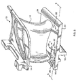
- Figure 1 shows a conventional turbine nozzle segment 10.
- the nozzle segment 10 is an investment casting that includes a vane 12 disposed between an outer band 14 and an inner band 16.
- a mounting flange 18 is formed on the radially inner side (or "cold side") 20 of the inner band 16 for mounting the nozzle segment 10 to stationary engine structure.
- the vane 12 defines an airfoil surface and has a hollow interior cavity through which a cooling medium can flow to cool the vane 12.
- a plurality of film cooling holes 22 extend radially through the inner band 16 so as to connect the radially outer side (or "hot side") 24 of the inner band 16 to a plenum (not shown in Figure 1) located on the cold side 20 of the inner band 16.
- the plenum functions as a source of a cooling medium, such as compressor discharge air, which passes through the film cooling holes 22.
- the film cooling holes 22 thus provide a cooling medium film on the inner band hot side 24 that extends therefrom to the aft edge of the inner band 16.
- the film cooling holes 22 are typically located forward of the mounting flange 18 because the cooling medium plenum is limited to a forward location due to structural requirements of the inner band 16. This places the film cooling holes substantially upstream of the inner band aft edge. Accordingly, the aft corner region 26 on the inner band hot side can receive inadequate cooling and experience local distress due to over-temperature, thermal stress, creep or bulk temperature induced low cycle fatigue.
- a method for modifying the cooling scheme of the nozzle segment 10 without redesigning the investment casting.
- the purpose of the cooling scheme modification is to improve cooling in the aft corner region 26 and minimize occurrences of local distress.
- This method can be implemented as a repair or an upgrade. That is, the method can be used in repairing distressed parts returned from service so as to avoid recurrences of the local distress or to upgrade new-make parts prior to entering service so as to avoid the local distress in the first place.
- "modifying" a component refers to structurally changing the component after the casting process.
- the method is described herein in the context of alleviating local distress on the inner band of a turbine nozzle segment, it should be noted that the method is not limited to inner bands or even nozzle segments. The method can be applied to any cooled turbine component having a tendency to show local distress due to inadequate cooling.
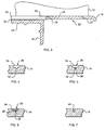
- the first step in the method is to form one or more channels 28 in the inner band hot side 24.
- the channels 28 begin at a point forward of the mounting flange 18 and extend to the aft edge of the inner band 16, thereby traversing the aft corner region 26 that is susceptible to local distress.
- the channels 28 are relatively shallow, but are of sufficient depth to connect to the cooling medium plenum 30 located on the inner band cold side 20, forward of the mounting flange 18.
- the channels 28 can be formed in any suitable manner including conventional machining, electrical discharge machining, water jet machining, electro-chemical machining, Pulsed Electro-chemical machining and laser machining.
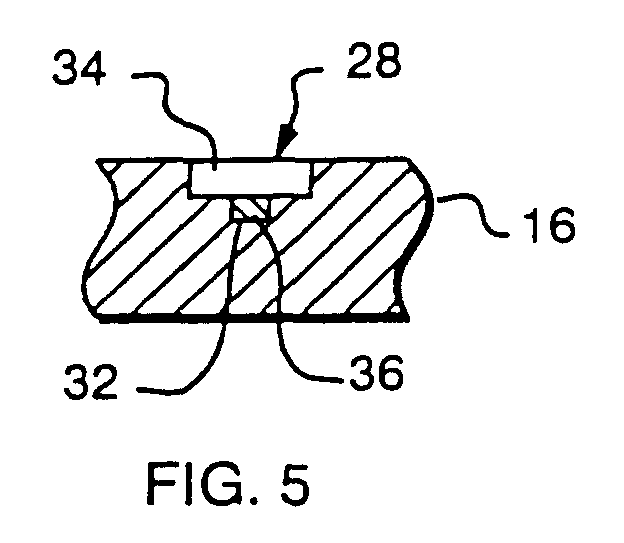
- each channel 28 has two sections: a lower section 32 and an upper section 34.
- the two sections 32, 34 extend parallel to one another, with the lower section 32 being the deeper, narrower section and the upper section 34 being the shallower, wider section.
- deeper and shallower refer to the distance that the bottom of each section 32, 34 is located from the hot side 24, not a particular dimension of a side wall of an individual section.
- the channels 28 can have a variety of forms and geometries.
- the lower sections 32 can be provided with structural features, such as turbulators, pin fins or the like, designed to enhance cooling by increasing heat transfer.
- each lower section 32 is filled with a removable material 36, as shown in Figure 5.
- removable material refers to any substance that can be removed after the channels 28 have been “patched” in the manner described below and without otherwise altering the nozzle segment 10. Suitable examples include ceramic materials, high temperature salts, or leachable materials such as copper-nickel alloys and low carbon steels.
- the next step is to fill each upper section 34 with a patch material 38 that covers the removable material 36 and completely fills the channels 38.
- the patch material 38 is applied by any suitable method such as metal plasma spray, electron beam physical vapor deposition, diffusion bonding or cladding.
- the patch material 38 becomes an integral part of the inner band 16 and thereby "patches" the channels 28.
- the patch material 38 is the same material (or at least a compatible material with similar properties) as the parent material of the nozzle segment 10 although in some cases, non-identical materials can be used. In the case of gas turbine engine components, this is usually a metallic material such as stainless steel, titanium and high temperature superalloys.
- the removable material 38 is removed from the lower section 32 of each channel 28, as shown in Figures 7 and 8. This can be accomplished by a number of methods, depending on the nature of the removable material 36. For instance, leachable materials are removed by causing an appropriate solvent to percolate through the material 36, thereby leaching the material 36 from the channel 28. High temperature salts would be removed by heating the nozzle segment 10 to the point that the salt would liquefy and drain away. Ceramic materials would be removed by placing the nozzle segment in an appropriate acid bath. After removal of the removable material 36, the nozzle segment is processed for the addition of protective environmental coatings and/or thermal barrier coatings, as would normally be applied to the part.
- Removal of the removable material 36 creates internal cooling passages 40 in the inner band 16 that extend from the cooling medium plenum 30 to the aft edge of the inner band 16.
- the internal passages 40 thus provide a flow of cooling medium through the aft corner region 26, thereby alleviating the local distress that would otherwise tend to occur in this region.
- the turbine nozzle segment 10 is simply used herein as an example to describe the present invention.
- the present invention is not limited to nozzle segments but can be applied to any cooled turbine component having a tendency to show local distress due to inadequate cooling.
- the applied cooling channels can take various forms and geometries as long as they connect to a cooling medium source.
- the surface area of the patch should be generally limited in size so that the patch strength is not required to be on the same order as the strength of the component substrate material. This will insure that the patch surface is structurally capable of withstanding the mechanical and thermal stresses.
Landscapes
- Engineering & Computer Science (AREA)
- Mechanical Engineering (AREA)
- General Engineering & Computer Science (AREA)
- Turbine Rotor Nozzle Sealing (AREA)
Abstract

Description
Claims (10)
- A method of modifying a gas turbine engine component (10) having a cooling medium source associated therewith, said method comprising:forming at least one channel (28) in said component (10), said channel (28) being in fluid communication with said cooling medium source;partially filling said channel (28) with a removable material (36);covering said removable material (36) with a patch material (38) so as to completely fill said channel (28); andremoving said removable material (36) from said channel (28) so as to create an internal cooling passage (40) in said component (10).
- The method of claim 1 wherein said internal passage (40) traverses a region (26) of said component (10) that is susceptible to local distress.
- The method of claim 1 or 2 wherein said removable material (36) is removed by leaching.
- The method of claim 1 or 2 wherein said removable material (36) is removed by heating said removable material (36).
- A method of modifying a gas turbine engine component (10) having a cooling medium source associated therewith, said method comprising:forming at least one channel (28) in a surface of said component (10), said channel (28) being in fluid communication with said cooling medium source and having a deeper, narrower section (32) and a shallower, wider section (34);filling said deeper, narrower section (32) of said channel (28) with a removable material (36);filling said shallower, wider section (34) of said channel (28) with a patch material (38) so as to cover said removable material (36); andremoving said removable material (36) from said channel (28) so as to create an internal cooling passage (40) in said component (10).
- The method of claim 5 wherein said internal passage (40) traverses a region (26) of said component (10) that is susceptible to local distress.
- The method of claim 5 or 6 wherein said removable material (36) is removed by leaching.
- The method of claim 5 or 6 wherein said removable material (36) is removed by heating said removable material (36).
- A modified gas turbine engine component (10) having a cooling medium source associated therewith, said component (10) being modified by the method of:forming at least one channel (28) in said component (10), said channel (28) being in fluid communication with said cooling medium source;partially filling said channel (28) with a removable material (36);covering said removable material (36) with a patch material (38) so as to completely fill said channel (28); andremoving said removable material (36) from said channel (28) so as to create an internal cooling passage (40) in said component (10).
- A modified gas turbine engine component (10) having a cooling medium source associated therewith, said component (10) being modified by the method of:forming at least one channel (28) in a surface of said component (10), said channel (28) being in fluid communication with said cooling medium source and having a deeper, narrower section (32) and a shallower, wider section (34);filling said deeper, narrower section (32) of said channel (28) with a removable material (36);filling said shallower, wider section (34) of said channel (28) with a patch material (38) so as to cover said removable material (36); andremoving said removable material (36) from said channel (28) so as to create an internal cooling passage (40) in said component (10).
Applications Claiming Priority (2)
| Application Number | Priority Date | Filing Date | Title |
|---|---|---|---|
| US726004 | 2000-11-29 | ||
| US09/726,004 US6427327B1 (en) | 2000-11-29 | 2000-11-29 | Method of modifying cooled turbine components |
Publications (3)
| Publication Number | Publication Date |
|---|---|
| EP1211385A2 true EP1211385A2 (en) | 2002-06-05 |
| EP1211385A3 EP1211385A3 (en) | 2003-11-12 |
| EP1211385B1 EP1211385B1 (en) | 2007-08-08 |
Family
ID=24916818
Family Applications (1)
| Application Number | Title | Priority Date | Filing Date |
|---|---|---|---|
| EP01310021A Expired - Lifetime EP1211385B1 (en) | 2000-11-29 | 2001-11-29 | Making cooling channels in turbine components |
Country Status (4)
| Country | Link |
|---|---|
| US (1) | US6427327B1 (en) |
| EP (1) | EP1211385B1 (en) |
| JP (1) | JP4398616B2 (en) |
| DE (1) | DE60129779T2 (en) |
Cited By (4)
| Publication number | Priority date | Publication date | Assignee | Title |
|---|---|---|---|---|
| WO2013121016A1 (en) * | 2012-02-17 | 2013-08-22 | Alstom Technology Ltd | Component for a thermal machine, in particular a gas turbine |
| WO2013120999A1 (en) * | 2012-02-17 | 2013-08-22 | Alstom Technology Ltd | Method for producing a near-surface cooling passage in a thermally highly stressed component, and component having such a passage |
| EP2518270A3 (en) * | 2011-04-27 | 2017-11-15 | General Electric Company | Component and methods of fabricating a coated component using multiple types of fillers |
| EP2511475B1 (en) * | 2011-04-11 | 2020-09-16 | General Electric Company | Method of fabricating a component for a gas turbine engine |
Families Citing this family (41)
| Publication number | Priority date | Publication date | Assignee | Title |
|---|---|---|---|---|
| US6617003B1 (en) * | 2000-11-06 | 2003-09-09 | General Electric Company | Directly cooled thermal barrier coating system |
| US20040115059A1 (en) * | 2002-12-12 | 2004-06-17 | Kehl Richard Eugene | Cored steam turbine bucket |
| US7216428B2 (en) * | 2003-03-03 | 2007-05-15 | United Technologies Corporation | Method for turbine element repairing |
| US7097424B2 (en) * | 2004-02-03 | 2006-08-29 | United Technologies Corporation | Micro-circuit platform |
| US20050217110A1 (en) * | 2004-04-06 | 2005-10-06 | Topal Valeriy I | Deposition repair of hollow items |
| US7220934B2 (en) * | 2005-06-07 | 2007-05-22 | United Technologies Corporation | Method of producing cooling holes in highly contoured airfoils |
| US7540083B2 (en) | 2005-09-28 | 2009-06-02 | Honeywell International Inc. | Method to modify an airfoil internal cooling circuit |
| US7717677B1 (en) | 2007-01-31 | 2010-05-18 | Florida Turbine Technologies, Inc. | Multi-metering and diffusion transpiration cooled airfoil |
| US7766617B1 (en) | 2007-03-06 | 2010-08-03 | Florida Turbine Technologies, Inc. | Transpiration cooled turbine airfoil |
| US8376706B2 (en) * | 2007-09-28 | 2013-02-19 | General Electric Company | Turbine airfoil concave cooling passage using dual-swirl flow mechanism and method |
| US20100284800A1 (en) * | 2009-05-11 | 2010-11-11 | General Electric Company | Turbine nozzle with sidewall cooling plenum |
| JP5578864B2 (en) * | 2010-01-20 | 2014-08-27 | 三菱重工業株式会社 | Repair method of wall member with flow path |
| US20140271974A1 (en) * | 2013-03-14 | 2014-09-18 | Honda Motor Co., Ltd. | Conforming cooling method and mold |
| US8673397B2 (en) | 2010-11-10 | 2014-03-18 | General Electric Company | Methods of fabricating and coating a component |
| US9249491B2 (en) | 2010-11-10 | 2016-02-02 | General Electric Company | Components with re-entrant shaped cooling channels and methods of manufacture |
| US8739404B2 (en) * | 2010-11-23 | 2014-06-03 | General Electric Company | Turbine components with cooling features and methods of manufacturing the same |
| US8753071B2 (en) | 2010-12-22 | 2014-06-17 | General Electric Company | Cooling channel systems for high-temperature components covered by coatings, and related processes |
| RU2536443C2 (en) | 2011-07-01 | 2014-12-27 | Альстом Текнолоджи Лтд | Turbine guide vane |
| US9249672B2 (en) | 2011-09-23 | 2016-02-02 | General Electric Company | Components with cooling channels and methods of manufacture |
| US20130086784A1 (en) | 2011-10-06 | 2013-04-11 | General Electric Company | Repair methods for cooled components |
| US9249670B2 (en) | 2011-12-15 | 2016-02-02 | General Electric Company | Components with microchannel cooling |
| US9435208B2 (en) | 2012-04-17 | 2016-09-06 | General Electric Company | Components with microchannel cooling |
| US9243503B2 (en) | 2012-05-23 | 2016-01-26 | General Electric Company | Components with microchannel cooled platforms and fillets and methods of manufacture |
| DE102013109116A1 (en) | 2012-08-27 | 2014-03-27 | General Electric Company (N.D.Ges.D. Staates New York) | Component with cooling channels and method of manufacture |
| US8974859B2 (en) | 2012-09-26 | 2015-03-10 | General Electric Company | Micro-channel coating deposition system and method for using the same |
| US9238265B2 (en) | 2012-09-27 | 2016-01-19 | General Electric Company | Backstrike protection during machining of cooling features |
| US9242294B2 (en) | 2012-09-27 | 2016-01-26 | General Electric Company | Methods of forming cooling channels using backstrike protection |
| US9562436B2 (en) | 2012-10-30 | 2017-02-07 | General Electric Company | Components with micro cooled patterned coating layer and methods of manufacture |
| US9200521B2 (en) | 2012-10-30 | 2015-12-01 | General Electric Company | Components with micro cooled coating layer and methods of manufacture |
| US20140126995A1 (en) * | 2012-11-06 | 2014-05-08 | General Electric Company | Microchannel cooled turbine component and method of forming a microchannel cooled turbine component |
| US9003657B2 (en) * | 2012-12-18 | 2015-04-14 | General Electric Company | Components with porous metal cooling and methods of manufacture |
| WO2014123841A1 (en) * | 2013-02-10 | 2014-08-14 | United Technologies Corporation | Removable film for airfoil surfaces |
| US9278462B2 (en) | 2013-11-20 | 2016-03-08 | General Electric Company | Backstrike protection during machining of cooling features |
| US9803939B2 (en) * | 2013-11-22 | 2017-10-31 | General Electric Company | Methods for the formation and shaping of cooling channels, and related articles of manufacture |
| US9476306B2 (en) | 2013-11-26 | 2016-10-25 | General Electric Company | Components with multi-layered cooling features and methods of manufacture |
| EP3084137A4 (en) * | 2013-12-19 | 2017-01-25 | United Technologies Corporation | Turbine airfoil cooling |
| CN104625655A (en) * | 2015-02-14 | 2015-05-20 | 杨光华 | Manufacturing method for curved hydraulic channel |
| US10815782B2 (en) | 2016-06-24 | 2020-10-27 | General Electric Company | Methods for repairing airfoil trailing edges to include ejection slots therein |
| US10465526B2 (en) | 2016-11-15 | 2019-11-05 | Rolls-Royce Corporation | Dual-wall airfoil with leading edge cooling slot |
| US10648341B2 (en) | 2016-11-15 | 2020-05-12 | Rolls-Royce Corporation | Airfoil leading edge impingement cooling |
| US10450873B2 (en) | 2017-07-31 | 2019-10-22 | Rolls-Royce Corporation | Airfoil edge cooling channels |
Family Cites Families (21)
| Publication number | Priority date | Publication date | Assignee | Title |
|---|---|---|---|---|
| US2641439A (en) * | 1947-10-01 | 1953-06-09 | Chrysler Corp | Cooled turbine or compressor blade |
| BE552543A (en) * | 1955-11-16 | |||
| US3613207A (en) * | 1969-06-05 | 1971-10-19 | Messerschmitt Boelkow Blohm | Method for covering and closing cooling channels of a combustion chamber |
| US4311433A (en) * | 1979-01-16 | 1982-01-19 | Westinghouse Electric Corp. | Transpiration cooled ceramic blade for a gas turbine |
| US4376004A (en) * | 1979-01-16 | 1983-03-08 | Westinghouse Electric Corp. | Method of manufacturing a transpiration cooled ceramic blade for a gas turbine |
| IL70146A0 (en) * | 1982-12-22 | 1984-02-29 | Gen Electric | Article with a fluid passage and method for making it |
| US5075966A (en) * | 1990-09-04 | 1991-12-31 | General Electric Company | Method for fabricating a hollow component for a rocket engine |
| US5249357A (en) * | 1993-01-27 | 1993-10-05 | The United States Of America As Represented By The Administrator Of The National Aeronautics And Space Administration | Method of fabricating a rocket engine combustion chamber |
| US5328331A (en) * | 1993-06-28 | 1994-07-12 | General Electric Company | Turbine airfoil with double shell outer wall |
| EP0730704B1 (en) * | 1993-11-24 | 1997-07-09 | United Technologies Corporation | Cooled turbine airfoil |
| US5626462A (en) * | 1995-01-03 | 1997-05-06 | General Electric Company | Double-wall airfoil |
| US5640767A (en) * | 1995-01-03 | 1997-06-24 | Gen Electric | Method for making a double-wall airfoil |
| US5820337A (en) * | 1995-01-03 | 1998-10-13 | General Electric Company | Double wall turbine parts |
| JPH09168927A (en) * | 1995-12-19 | 1997-06-30 | Hitachi Ltd | Repair method for moving blade and stationary blade for gas turbine |
| US5771577A (en) * | 1996-05-17 | 1998-06-30 | General Electric Company | Method for making a fluid cooled article with protective coating |
| US6000908A (en) * | 1996-11-05 | 1999-12-14 | General Electric Company | Cooling for double-wall structures |
| JPH10184309A (en) * | 1996-12-26 | 1998-07-14 | Mitsubishi Heavy Ind Ltd | Plug cover installation method for cooling groove |
| US5875549A (en) * | 1997-03-17 | 1999-03-02 | Siemens Westinghouse Power Corporation | Method of forming internal passages within articles and articles formed by same |
| US6027306A (en) * | 1997-06-23 | 2000-02-22 | General Electric Company | Turbine blade tip flow discouragers |
| US6214248B1 (en) * | 1998-11-12 | 2001-04-10 | General Electric Company | Method of forming hollow channels within a component |
| US6174133B1 (en) * | 1999-01-25 | 2001-01-16 | General Electric Company | Coolable airfoil |
-
2000
- 2000-11-29 US US09/726,004 patent/US6427327B1/en not_active Expired - Fee Related
-
2001
- 2001-11-29 DE DE60129779T patent/DE60129779T2/en not_active Expired - Lifetime
- 2001-11-29 JP JP2001363608A patent/JP4398616B2/en not_active Expired - Fee Related
- 2001-11-29 EP EP01310021A patent/EP1211385B1/en not_active Expired - Lifetime
Cited By (8)
| Publication number | Priority date | Publication date | Assignee | Title |
|---|---|---|---|---|
| EP2511475B1 (en) * | 2011-04-11 | 2020-09-16 | General Electric Company | Method of fabricating a component for a gas turbine engine |
| EP2518270A3 (en) * | 2011-04-27 | 2017-11-15 | General Electric Company | Component and methods of fabricating a coated component using multiple types of fillers |
| WO2013121016A1 (en) * | 2012-02-17 | 2013-08-22 | Alstom Technology Ltd | Component for a thermal machine, in particular a gas turbine |
| WO2013120999A1 (en) * | 2012-02-17 | 2013-08-22 | Alstom Technology Ltd | Method for producing a near-surface cooling passage in a thermally highly stressed component, and component having such a passage |
| CH706090A1 (en) * | 2012-02-17 | 2013-08-30 | Alstom Technology Ltd | A method for manufacturing a near-surface cooling passage in a thermally highly stressed component and component with such a channel. |
| CH706107A1 (en) * | 2012-02-17 | 2013-08-30 | Alstom Technology Ltd | Component of a thermal machine, in particular a gas turbine. |
| US9777577B2 (en) | 2012-02-17 | 2017-10-03 | Ansaldo Energia Ip Uk Limited | Component for a thermal machine, in particular a gas turbine |
| US9869479B2 (en) | 2012-02-17 | 2018-01-16 | Ansaldo Energia Ip Uk Limited | Method for producing a near-surface cooling passage in a thermally highly stressed component, and component having such a passage |
Also Published As
| Publication number | Publication date |
|---|---|
| DE60129779T2 (en) | 2008-04-30 |
| EP1211385A3 (en) | 2003-11-12 |
| JP4398616B2 (en) | 2010-01-13 |
| US20020062544A1 (en) | 2002-05-30 |
| US6427327B1 (en) | 2002-08-06 |
| EP1211385B1 (en) | 2007-08-08 |
| DE60129779D1 (en) | 2007-09-20 |
| JP2002201962A (en) | 2002-07-19 |
Similar Documents
| Publication | Publication Date | Title |
|---|---|---|
| EP1211385B1 (en) | Making cooling channels in turbine components | |
| US11059093B2 (en) | Additively manufactured core for use in casting an internal cooling circuit of a gas turbine engine component | |
| US11268387B2 (en) | Splayed tip features for gas turbine engine airfoil | |
| EP1422381B1 (en) | Method of repairing a turbine nozzle segment, and turbine nozzle segment | |
| US10415403B2 (en) | Cooled blisk for gas turbine engine | |
| EP2982471B1 (en) | Methods for manufacturing a turbine nozzle with single crystal alloy nozzle segments | |
| PL202702B1 (en) | Turbine nozzle segment, method of repairing a such nozzle segment and replacement casting for use in repairing the turbine nozzle segments | |
| EP2995864B1 (en) | Film cooling circuit for a combustor liner and method of manufacturing the film cooling circuit | |
| EP4028643B1 (en) | Turbine blade, method of manufacturing a turbine blade and method of refurbishing a turbine blade | |
| US8292587B2 (en) | Turbine blade assemblies and methods of manufacturing the same | |
| JP2006170204A (en) | Turbine nozzle segment and repair method thereof | |
| EP3623577A1 (en) | Gas turbine engine airfoil tip cooling arrangement with purge partition | |
| EP3441673B1 (en) | Combustor panels having airflow distribution features | |
| EP3477202B1 (en) | Float wall combustor panels having airflow distribution features | |
| KR102764478B1 (en) | Airfoil with internal crossover passages and pin array | |
| US10549338B2 (en) | System and process to provide self-supporting additive manufactured ceramic core | |
| US12497896B2 (en) | Airfoil assembly with platform film holes | |
| US20190375000A1 (en) | Method for casting cooling holes for an internal cooling circuit of a gas turbine engine component |
Legal Events
| Date | Code | Title | Description |
|---|---|---|---|
| PUAI | Public reference made under article 153(3) epc to a published international application that has entered the european phase |
Free format text: ORIGINAL CODE: 0009012 |
|
| AK | Designated contracting states |
Kind code of ref document: A2 Designated state(s): AT BE CH CY DE DK ES FI FR GB GR IE IT LI LU MC NL PT SE TR |
|
| AX | Request for extension of the european patent |
Free format text: AL;LT;LV;MK;RO;SI |
|
| PUAL | Search report despatched |
Free format text: ORIGINAL CODE: 0009013 |
|
| AK | Designated contracting states |
Kind code of ref document: A3 Designated state(s): AT BE CH CY DE DK ES FI FR GB GR IE IT LI LU MC NL PT SE TR |
|
| AX | Request for extension of the european patent |
Extension state: AL LT LV MK RO SI |
|
| RIC1 | Information provided on ipc code assigned before grant |
Ipc: 7B 23P 15/02 B Ipc: 7F 01D 5/18 A |
|
| 17P | Request for examination filed |
Effective date: 20040512 |
|
| AKX | Designation fees paid |
Designated state(s): DE FR GB IT |
|
| 17Q | First examination report despatched |
Effective date: 20041008 |
|
| GRAP | Despatch of communication of intention to grant a patent |
Free format text: ORIGINAL CODE: EPIDOSNIGR1 |
|
| GRAS | Grant fee paid |
Free format text: ORIGINAL CODE: EPIDOSNIGR3 |
|
| GRAA | (expected) grant |
Free format text: ORIGINAL CODE: 0009210 |
|
| AK | Designated contracting states |
Kind code of ref document: B1 Designated state(s): DE FR GB IT |
|
| REG | Reference to a national code |
Ref country code: GB Ref legal event code: FG4D |
|
| REF | Corresponds to: |
Ref document number: 60129779 Country of ref document: DE Date of ref document: 20070920 Kind code of ref document: P |
|
| ET | Fr: translation filed | ||
| PLBE | No opposition filed within time limit |
Free format text: ORIGINAL CODE: 0009261 |
|
| STAA | Information on the status of an ep patent application or granted ep patent |
Free format text: STATUS: NO OPPOSITION FILED WITHIN TIME LIMIT |
|
| 26N | No opposition filed |
Effective date: 20080509 |
|
| PGFP | Annual fee paid to national office [announced via postgrant information from national office to epo] |
Ref country code: DE Payment date: 20091127 Year of fee payment: 9 |
|
| PGFP | Annual fee paid to national office [announced via postgrant information from national office to epo] |
Ref country code: FR Payment date: 20091201 Year of fee payment: 9 Ref country code: GB Payment date: 20091125 Year of fee payment: 9 Ref country code: IT Payment date: 20091126 Year of fee payment: 9 |
|
| GBPC | Gb: european patent ceased through non-payment of renewal fee |
Effective date: 20101129 |
|
| REG | Reference to a national code |
Ref country code: FR Ref legal event code: ST Effective date: 20110801 |
|
| REG | Reference to a national code |
Ref country code: DE Ref legal event code: R119 Ref document number: 60129779 Country of ref document: DE Effective date: 20110601 Ref country code: DE Ref legal event code: R119 Ref document number: 60129779 Country of ref document: DE Effective date: 20110531 |
|
| PG25 | Lapsed in a contracting state [announced via postgrant information from national office to epo] |
Ref country code: FR Free format text: LAPSE BECAUSE OF NON-PAYMENT OF DUE FEES Effective date: 20101130 |
|
| PG25 | Lapsed in a contracting state [announced via postgrant information from national office to epo] |
Ref country code: GB Free format text: LAPSE BECAUSE OF NON-PAYMENT OF DUE FEES Effective date: 20101129 |
|
| PG25 | Lapsed in a contracting state [announced via postgrant information from national office to epo] |
Ref country code: IT Free format text: LAPSE BECAUSE OF NON-PAYMENT OF DUE FEES Effective date: 20101129 |
|
| PG25 | Lapsed in a contracting state [announced via postgrant information from national office to epo] |
Ref country code: DE Free format text: LAPSE BECAUSE OF NON-PAYMENT OF DUE FEES Effective date: 20110531 |