EP1211142A2 - Waterproof structure for a wire harness - Google Patents
Waterproof structure for a wire harness Download PDFInfo
- Publication number
- EP1211142A2 EP1211142A2 EP01403054A EP01403054A EP1211142A2 EP 1211142 A2 EP1211142 A2 EP 1211142A2 EP 01403054 A EP01403054 A EP 01403054A EP 01403054 A EP01403054 A EP 01403054A EP 1211142 A2 EP1211142 A2 EP 1211142A2
- Authority
- EP
- European Patent Office
- Prior art keywords
- wire harness
- waterproof structure
- external surface
- wire
- electrical cables
- Prior art date
- Legal status (The legal status is an assumption and is not a legal conclusion. Google has not performed a legal analysis and makes no representation as to the accuracy of the status listed.)
- Withdrawn
Links
Images


Classifications
-
- B—PERFORMING OPERATIONS; TRANSPORTING
- B60—VEHICLES IN GENERAL
- B60R—VEHICLES, VEHICLE FITTINGS, OR VEHICLE PARTS, NOT OTHERWISE PROVIDED FOR
- B60R16/00—Electric or fluid circuits specially adapted for vehicles and not otherwise provided for; Arrangement of elements of electric or fluid circuits specially adapted for vehicles and not otherwise provided for
- B60R16/02—Electric or fluid circuits specially adapted for vehicles and not otherwise provided for; Arrangement of elements of electric or fluid circuits specially adapted for vehicles and not otherwise provided for electric constitutive elements
- B60R16/0207—Wire harnesses
Definitions
- the present invention generally pertains to a waterproof structure for a wire harness mountable in a vehicle, e.g. an automobile.
- the invention concerns a waterproof structure resistant to bending stress.
- the invention also relates to a wire harness including such a waterproof structure.
- the invention further relates to a method of preparing such a waterproof structure or wire harness.
- Wire harnesses are commonly used for connecting electrical apparatuses to one another in a vehicle such as automobile. In certain cases, they are mounted in the parts of the vehicle where a risk of water contamination is high. In such parts, water tends to penetrate into the wire harness from the periphery of a connector mounted at an end portion of the wire harness. After having penetrated, the water then advances along the wire harness by capillary effect generated between wire's cores, and reaches the other end portion of the wire harness, where an electronic control unit (ECU) is commonly mounted. The ECU is then liable to damage by water.
- ECU electronice control unit
- a vehicle 12 is attached to a trailer 13a through a towing bar or rope, and a wire harness 11 is wired along the trailer 13, so that the turn indicators of the latter can be switched from the vehicle 12.
- a jet ski 14 or other water craft is carried on the trailer 13 and unloaded onto water W, the trailer 13 will have to be submerged into the water W.
- the wire harness may be subjected to a waterproofing treatment, such as described in Japanese Utility Model published under No. HEI 6-86221.
- the waterproofing treatment is performed as follows.
- the electrical cables constituting a wire harness are first stripped of their vinyl tube at a given position chosen in their length direction.
- Each electrical cable contains a plurality of wire cores, which are thus exposed, leaving spaces between them. These spaces are filled with waterproofing material, and the external surface of the latter is further wrapped with a waterproof insulator coating. In this manner, the capillary flow of water between the wire cores can be stopped at the above-mentioned given position, where the waterproofing material is located.
- a wire harness when wired e.g. between the vehicle 12 and the trailer 13 as exemplified above, undergoes frequent bending.
- the waterproofing structure such as described above suffers a disintegration between the waterproofing material and the wire cores, or between the waterproof insulator coating and wire cores, thereby forming interstices. Water then enters into and moves along the interstices.
- a main object of the present invention is therefore to provide a waterproof structure for a wire harness which is substantially unaffected by frequent bending and thus can be applied to frequently bending parts of a vehicle, without losing its initial waterproofing capacity.
- a waterproof structure applicable to a wire harness having a length direction and comprising a plurality of electrical cables.
- Each of the electrical cables includes wire cores and a tubular coating, and the electrical cables are respectively stripped of the tubular coating at a same given portion chosen in the length direction of the wire harness, to expose their wire cores.
- the exposed wire cores are then adhered to one another, thereby forming an aggregated external surface.
- the aggregated external surface is further provided with a waterproofing material.
- the above waterproof structure further comprises a bend-preventing means extending along at least the aggregated external surface in the length direction of the wire harness.
- the waterproofing material has a substantially tubular shape with an internal circular face, and includes an adhering material on the internal circular face, so that the adhering material can be adhered to the aggregated external surface.
- the bend-preventing means comprises at least one bar made of resin material.
- the waterproof structure is adapted for installation on a wire harness wired between a vehicle and a trailer linked thereto.
- the invention also relates to a wire harness comprising a waterproof structure, the wire harness having a length direction and comprising a plurality of electrical cables.
- Each of the electrical cables includes wire cores and a tubular coating, and the electrical cables are respectively stripped of the tubular coating at a same given portion chosen in the length direction of the wire harness, to expose the wire cores.
- the exposed wire cores are adhered to one another, thereby forming an aggregated external surface.
- the aggregated external surface is provided with a waterproofing material.
- the waterproof structure further comprises a bend-preventing means extending along at least the aggregated external surface in the length direction of the wire harness.
- the waterproofing material preferably has a substantially tubular shape with an internal circular face, and includes an adhering material on the internal circular face, so that the adhering material can be adhered to the aggregated external surface.
- the bend-preventing means preferably comprises at least one bar made of resin material.
- the waterproof structure is preferably adapted for installation on a wire harness wired between a vehicle and a trailer linked thereto.
- the invention further relates to a method of preparing a waterproof structure applicable to a wire harness having a length direction and comprising a plurality of electrical cables, each of the electrical cables including wire cores and a tubular coating.
- the method comprises the steps of:
- the waterproofing material-providing process comprises providing a waterproofing material having a substantially tubular shape with an internal circular face, and providing an adhering material on the internal circular face, so that the adhering material can be adhered to the aggregated external surface.
- the waterproof structure is equipped with bend-preventing material, so that even when the wire harness is subjected to frequent bending, the waterproof structure is prevented from bending, and stays intact.
- the waterproof structure is no longer vulnerable to repeated bending, and secures its impermeable feature.
- Figs.2 shows a corrugated tube mounted around a wire harness 1.
- First and second ends of the wire harness 1 are provided respectively with a first connector 2 and a second connector 3.
- the first connector 2 is linked to electrical devices loaded in a vehicle (not shown in the figure), whereas the second connector 3 is linked to a trailer (not shown in the figure).
- One of the electrical devices lights on or off the turn indicators of the trailer via the wire harness 1.
- the trailer 13 is towed by the vehicle 12 through a metallic traction member.
- the wire harness 1 is wired along this traction member.
- the wire harness 1 contains a bundle of electrical cables 4, and each electrical cable 4 is composed of a wire core portion 4a including individual wire cores, and a tubular coating 4b e.g. vinyl tube.
- each electrical cable 4 (substantially half way point along the length) is stripped of the tubular coating 4b, so as to bare the wire cores.
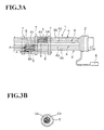
- These wire cores are adhered to one another by soldering, so as to form an aggregated external surface (Figs.3A and 3B).
- the bared and soldered wire cores are wrapped with a heat-shrinkable tube 5 (waterproofing material), whose internal circular surface is provided with an adhering material 5a.
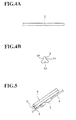
- the section where the heat-shrinkable tube 5 is applied is supported by a bar made of resin material 6 as a bend-preventing member (Fig.4).
- the bar 6 is formed of e.g. a hard vinyl chloride, and firmly fixed along the heat-shrinkable tube 5 by e.g. a PVC tape 7.
- the bar made of resin material 6 is provided with one or several longitudinal recesses 6a, inside each of which extends an electrical cable 4.
- the resin bar 6 can prevent electric leakage by virtue of its material characteristics. It also possesses sufficient strength, such that it can prevent flexing of the section where the heat-shrinkable tube 5 is applied.
- Fig.2 also shows a protection cap 8 mounted on the first connector 2.
- the water soaked up via the wire cores is stopped from moving further, by virtue of the waterproof structure, in which the wire cores are soldered and protected by the heat-shrinkable tube 5.
- the waterproof section is supported by the bar made of resin material 6, which protects the waterproof structure, even when the harness is subjected to frequent bending.
- the bend-preventing means is composed of the simple bar made of resin material 6.
- the waterproof structure can be prepared very economically.
- the waterproofing material is not limited to a heat-shrinkable tube, but can be a tape.
- the waterproof section is equipped with bend-preventing material, so that even when the wire harness is subjected to frequent bending, the waterproof structure is prevented from bending, and stays intact.
- the bend-preventing means contain at least one bar made of resin material, the structure is simple and the construction costs are lowered. Nonetheless, the waterproof structure is efficiently prevented from bending and suffering from water penetration.
- the waterproof structure of the invention is preferably applied to a wire harness used under frequent bending conditions, such as one wired on a traction bar between a vehicle and a trailer.
Landscapes
- Engineering & Computer Science (AREA)
- Mechanical Engineering (AREA)
- Insulated Conductors (AREA)
- Cable Accessories (AREA)
- Installation Of Indoor Wiring (AREA)
Abstract
Description
Claims (7)
- A waterproof structure applicable to a wire harness (1) having a length direction and comprising a plurality of electrical cables (4), each of the electrical cables (4) including wire cores and a tubular coating (4b), the electrical cables (4) being respectively stripped of the tubular coating (4b) at a same given portion chosen in the length direction of the wire harness (1), to expose the wire cores, characterised in that;
said exposed wire cores are adhered to one another, thereby forming an aggregated external surface;
said aggregated external surface is provided with a waterproofing material (5); and
said waterproof structure further comprises a bend-preventing means extending along at least said aggregated external surface in said length direction of said wire harness (1). - The waterproof structure according to claim 1, wherein said waterproofing material (5) has a substantially tubular shape with an internal circular face, and includes an adhering material (5a) on said internal circular face, so that said adhering material (5a) can be adhered to said aggregated external surface.
- The waterproof structure according to claim 1 or 2, wherein said bend-preventing means comprises at least one bar (6) made of resin material.
- The waterproof structure according to any one of claims 1 to 3, adapted for installation on a wire harness (1) wired between a vehicle (12) and a trailer (13) linked thereto.
- A wire harness comprising a waterproof structure defined in any one of claims 1 to 4.
- A method of preparing a waterproof structure applicable to a wire harness (1) having a length direction and comprising a plurality of electrical cables (4), each of the electrical cables (4) including wire cores and a tubular coating (4b), characterised in that said method comprises the steps of:stripping the electrical cables (4) respectively of said tubular coating (4b) at a same given portion chosen in said length direction of said wire harness (1), so that said wire cores are exposed;adhering said exposed wire cores to one another, thereby forming an aggregated external surface;providing said aggregated external surface with a waterproofing material (5); andproviding said waterproof structure with a bend-preventing means extending along at least said aggregated external surface in said length direction of said wire harness (1).
- The method according to claim 6, wherein said waterproofing material-providing process comprises providing a waterproofing material (5) having a substantially tubular shape with an internal circular face, and providing an adhering material (5a) on said internal circular face, so that said adhering material (5a) can be adhered to said aggregated external surface.
Applications Claiming Priority (2)
| Application Number | Priority Date | Filing Date | Title |
|---|---|---|---|
| JP2000362798 | 2000-11-29 | ||
| JP2000362798A JP2002170432A (en) | 2000-11-29 | 2000-11-29 | Wire harness waterproof structure |
Publications (2)
| Publication Number | Publication Date |
|---|---|
| EP1211142A2 true EP1211142A2 (en) | 2002-06-05 |
| EP1211142A3 EP1211142A3 (en) | 2003-04-16 |
Family
ID=18834012
Family Applications (1)
| Application Number | Title | Priority Date | Filing Date |
|---|---|---|---|
| EP01403054A Withdrawn EP1211142A3 (en) | 2000-11-29 | 2001-11-28 | Waterproof structure for a wire harness |
Country Status (3)
| Country | Link |
|---|---|
| US (1) | US20020062975A1 (en) |
| EP (1) | EP1211142A3 (en) |
| JP (1) | JP2002170432A (en) |
Cited By (1)
| Publication number | Priority date | Publication date | Assignee | Title |
|---|---|---|---|---|
| EP1502822A1 (en) * | 2003-07-29 | 2005-02-02 | Sumitomo Wiring Systems, Ltd. | Method of protecting a wire harness from water penetration |
Families Citing this family (14)
| Publication number | Priority date | Publication date | Assignee | Title |
|---|---|---|---|---|
| USD530671S1 (en) * | 2004-01-12 | 2006-10-24 | Reedex Inc. | Vehicle-to-trailer coiled electrical-cable |
| JP5117008B2 (en) * | 2006-03-22 | 2013-01-09 | 古河電気工業株式会社 | Electric wire core water stop treatment structure and electric wire core water stop treatment method |
| JP4525674B2 (en) * | 2006-12-28 | 2010-08-18 | 住友電装株式会社 | Water stop structure of splice |
| JP5320809B2 (en) * | 2008-05-08 | 2013-10-23 | 住友電装株式会社 | Water stop structure of wire harness and method of forming water stop |
| TWI537991B (en) * | 2010-08-26 | 2016-06-11 | A flexible cable with a waterproof structure | |
| JP5581929B2 (en) * | 2010-09-15 | 2014-09-03 | 住友電装株式会社 | Waterproof structure of wire harness |
| JP5957286B2 (en) * | 2012-05-09 | 2016-07-27 | 矢崎総業株式会社 | Wire harness water stop structure |
| US20140076628A1 (en) * | 2012-09-20 | 2014-03-20 | Icore International, Inc. | Rigidified non-conduited electrical harnesses |
| KR101625869B1 (en) * | 2013-10-04 | 2016-05-31 | 손종채 | A waterproof method for under water |
| JP5935787B2 (en) * | 2013-11-27 | 2016-06-15 | 住友電装株式会社 | Wire harness and wire harness manufacturing method |
| JP6210381B2 (en) * | 2014-08-22 | 2017-10-11 | 住友電装株式会社 | Shield conductive path |
| JP6281448B2 (en) * | 2014-09-03 | 2018-02-21 | 住友電装株式会社 | Conductive path |
| CN107275812A (en) * | 2017-06-21 | 2017-10-20 | 安徽博识电子科技有限公司 | One kind towing optical cable docking facilities |
| US11769609B1 (en) * | 2022-05-05 | 2023-09-26 | Dsm&T Company Inc. | Moisture resistant seal for electrical cable assemblies |
Family Cites Families (4)
| Publication number | Priority date | Publication date | Assignee | Title |
|---|---|---|---|---|
| US3789099A (en) * | 1971-11-09 | 1974-01-29 | Western Electric Co | Methods of manufacturing waterproof cable |
| JPH03280365A (en) * | 1990-03-28 | 1991-12-11 | Yazaki Corp | Waterproof seal structure of wire hardness |
| JP2584507Y2 (en) * | 1993-05-24 | 1998-11-05 | 住友電装株式会社 | Wire waterproof structure |
| JPH0945380A (en) * | 1995-08-03 | 1997-02-14 | Sumitomo Wiring Syst Ltd | Wire harness splice structure |
-
2000
- 2000-11-29 JP JP2000362798A patent/JP2002170432A/en not_active Abandoned
-
2001
- 2001-11-28 EP EP01403054A patent/EP1211142A3/en not_active Withdrawn
- 2001-11-29 US US09/995,715 patent/US20020062975A1/en not_active Abandoned
Cited By (2)
| Publication number | Priority date | Publication date | Assignee | Title |
|---|---|---|---|---|
| EP1502822A1 (en) * | 2003-07-29 | 2005-02-02 | Sumitomo Wiring Systems, Ltd. | Method of protecting a wire harness from water penetration |
| US6930252B2 (en) | 2003-07-29 | 2005-08-16 | Sumitomo Wiring Systems, Inc. | Method and apparatus for waterproofing a wire harness |
Also Published As
| Publication number | Publication date |
|---|---|
| EP1211142A3 (en) | 2003-04-16 |
| US20020062975A1 (en) | 2002-05-30 |
| JP2002170432A (en) | 2002-06-14 |
Similar Documents
| Publication | Publication Date | Title |
|---|---|---|
| US20020062975A1 (en) | Waterproof structure for a wire harness | |
| US8367927B2 (en) | Waterproofing method for wire and wire having waterproof part formed by the waterproofing method | |
| US10692628B2 (en) | Wiring member | |
| US6631095B1 (en) | Seismic conductive rope lead-in cable | |
| US8704088B2 (en) | Electrical connecting cable | |
| EP2854232A1 (en) | Waterproof structure of wire harness with connector | |
| EP2161787A1 (en) | Method of waterproofing splice area and wiring structure for automobile wire harness with splice area | |
| JPH09223412A (en) | Wire wiring structure | |
| CA1162768A (en) | Optical fiber cable | |
| CA1158327A (en) | Moisture-proofing of electrical cable with an outer layer electrochemically similar to the core | |
| GB2304228A (en) | Cable sleeve taping | |
| CA1250490A (en) | Faired umbilical cable | |
| JPH041528Y2 (en) | ||
| JP3486716B2 (en) | Wire harness | |
| JPH04488Y2 (en) | ||
| JPH0646185Y2 (en) | Compressed wire connection device for insulation coated wires | |
| JPH0612921A (en) | Electric power optical composite submarine cable | |
| JPH0321163Y2 (en) | ||
| JPH0423202Y2 (en) | ||
| JPS5922766Y2 (en) | Double sheathed cable bulling eye attachment device | |
| JPH07163034A (en) | Grommet mounting method for wire harness | |
| EP2458686A2 (en) | Line junction | |
| KR20170073955A (en) | Amour pot and cable connecting structure | |
| JPH10246845A (en) | Pipes and pipe cables | |
| JPS587116A (en) | Anchor part for overhead earth wire |
Legal Events
| Date | Code | Title | Description |
|---|---|---|---|
| PUAI | Public reference made under article 153(3) epc to a published international application that has entered the european phase |
Free format text: ORIGINAL CODE: 0009012 |
|
| 17P | Request for examination filed |
Effective date: 20011207 |
|
| AK | Designated contracting states |
Kind code of ref document: A2 Designated state(s): AT BE CH CY DE DK ES FI FR GB GR IE IT LI LU MC NL PT SE TR |
|
| AX | Request for extension of the european patent |
Free format text: AL;LT;LV;MK;RO;SI |
|
| PUAL | Search report despatched |
Free format text: ORIGINAL CODE: 0009013 |
|
| AK | Designated contracting states |
Designated state(s): AT BE CH CY DE DK ES FI FR GB GR IE IT LI LU MC NL PT SE TR |
|
| AX | Request for extension of the european patent |
Extension state: AL LT LV MK RO SI |
|
| AKX | Designation fees paid |
Designated state(s): DE FR GB |
|
| GRAP | Despatch of communication of intention to grant a patent |
Free format text: ORIGINAL CODE: EPIDOSNIGR1 |
|
| STAA | Information on the status of an ep patent application or granted ep patent |
Free format text: STATUS: THE APPLICATION HAS BEEN WITHDRAWN |
|
| 18W | Application withdrawn |
Effective date: 20041019 |