EP1210912A2 - Instrument for extroverting blood vessel - Google Patents
Instrument for extroverting blood vessel Download PDFInfo
- Publication number
- EP1210912A2 EP1210912A2 EP01127428A EP01127428A EP1210912A2 EP 1210912 A2 EP1210912 A2 EP 1210912A2 EP 01127428 A EP01127428 A EP 01127428A EP 01127428 A EP01127428 A EP 01127428A EP 1210912 A2 EP1210912 A2 EP 1210912A2
- Authority
- EP
- European Patent Office
- Prior art keywords
- blood vessel
- wire
- extroverting
- members
- diameter
- Prior art date
- Legal status (The legal status is an assumption and is not a legal conclusion. Google has not performed a legal analysis and makes no representation as to the accuracy of the status listed.)
- Withdrawn
Links
- 210000004204 blood vessel Anatomy 0.000 title claims abstract description 166
- 230000007246 mechanism Effects 0.000 claims abstract description 33
- 238000003780 insertion Methods 0.000 claims description 37
- 230000037431 insertion Effects 0.000 claims description 37
- 239000000463 material Substances 0.000 claims description 31
- 230000001105 regulatory effect Effects 0.000 claims description 23
- 239000013013 elastic material Substances 0.000 claims description 2
- 238000000034 method Methods 0.000 description 11
- 238000010276 construction Methods 0.000 description 7
- 239000007769 metal material Substances 0.000 description 7
- 239000011347 resin Substances 0.000 description 7
- 229920005989 resin Polymers 0.000 description 7
- 229910045601 alloy Inorganic materials 0.000 description 6
- 239000000956 alloy Substances 0.000 description 6
- 230000000694 effects Effects 0.000 description 5
- 239000010935 stainless steel Substances 0.000 description 5
- 229910001220 stainless steel Inorganic materials 0.000 description 5
- 229910001000 nickel titanium Inorganic materials 0.000 description 4
- 230000003872 anastomosis Effects 0.000 description 3
- 201000010099 disease Diseases 0.000 description 3
- 208000037265 diseases, disorders, signs and symptoms Diseases 0.000 description 3
- 229910000838 Al alloy Inorganic materials 0.000 description 2
- 229910001069 Ti alloy Inorganic materials 0.000 description 2
- RTAQQCXQSZGOHL-UHFFFAOYSA-N Titanium Chemical compound [Ti] RTAQQCXQSZGOHL-UHFFFAOYSA-N 0.000 description 2
- XAGFODPZIPBFFR-UHFFFAOYSA-N aluminium Chemical compound [Al] XAGFODPZIPBFFR-UHFFFAOYSA-N 0.000 description 2
- 229910052782 aluminium Inorganic materials 0.000 description 2
- 238000005452 bending Methods 0.000 description 2
- 239000010936 titanium Substances 0.000 description 2
- 229910052719 titanium Inorganic materials 0.000 description 2
- 208000007536 Thrombosis Diseases 0.000 description 1
- 238000004026 adhesive bonding Methods 0.000 description 1
- 230000015572 biosynthetic process Effects 0.000 description 1
- 238000007796 conventional method Methods 0.000 description 1
- -1 e.g. Substances 0.000 description 1
- 210000003038 endothelium Anatomy 0.000 description 1
- 238000002844 melting Methods 0.000 description 1
- 230000008018 melting Effects 0.000 description 1
- 238000001356 surgical procedure Methods 0.000 description 1
- 210000003813 thumb Anatomy 0.000 description 1
- 238000003466 welding Methods 0.000 description 1
Images


Classifications
-
- A—HUMAN NECESSITIES
- A61—MEDICAL OR VETERINARY SCIENCE; HYGIENE
- A61B—DIAGNOSIS; SURGERY; IDENTIFICATION
- A61B17/00—Surgical instruments, devices or methods
- A61B17/11—Surgical instruments, devices or methods for performing anastomosis; Buttons for anastomosis
-
- A—HUMAN NECESSITIES
- A61—MEDICAL OR VETERINARY SCIENCE; HYGIENE
- A61B—DIAGNOSIS; SURGERY; IDENTIFICATION
- A61B17/00—Surgical instruments, devices or methods
- A61B17/30—Surgical pincettes, i.e. surgical tweezers without pivotal connections
-
- A—HUMAN NECESSITIES
- A61—MEDICAL OR VETERINARY SCIENCE; HYGIENE
- A61B—DIAGNOSIS; SURGERY; IDENTIFICATION
- A61B17/00—Surgical instruments, devices or methods
- A61B17/30—Surgical pincettes, i.e. surgical tweezers without pivotal connections
- A61B2017/303—Surgical pincettes, i.e. surgical tweezers without pivotal connections with four or more legs
-
- A—HUMAN NECESSITIES
- A61—MEDICAL OR VETERINARY SCIENCE; HYGIENE
- A61B—DIAGNOSIS; SURGERY; IDENTIFICATION
- A61B90/00—Instruments, implements or accessories specially adapted for surgery or diagnosis and not covered by any of the groups A61B1/00 - A61B50/00, e.g. for luxation treatment or for protecting wound edges
- A61B90/03—Automatic limiting or abutting means, e.g. for safety
- A61B2090/033—Abutting means, stops, e.g. abutting on tissue or skin
- A61B2090/034—Abutting means, stops, e.g. abutting on tissue or skin abutting on parts of the device itself
Definitions
- a material substantially elastic in the range of deformation caused during use of the blood vessel extroverting instrument 1A for example, a superelastic material (superelastic alloy) such as a nickel-titanium alloy is preferred for the ring portion 2.
- a superelastic material such as a nickel-titanium alloy
- the ring portion 2 is formed of such a superelastic alloy, its shape close to a circle (perfect circle) can be maintained even when the ring portion 2 is deformed by being changed in diameter.
- the ring portion 2 formed of such a superelastic alloy has improved durability.
- Proximal ends of the grip portions 32a and 32b are connected to each other.
- the grip portions 32a and 32b are formed by bending (curving) a central portion of a member in the form of a plate made of a metallic material such as stainless steel or a material selected from various resin materials, etc.
- the blood vessel extroverting instrument 1B shown in Fig. 4 is used to turn an end of a blood vessel inside out, as is the blood vessel extroverting instrument 1A, and has a ring portion 4 positioned at its distal end, arm portions 51a and 51b for supporting the ring portion 2, and a supporting portion 5.
- the construction of each portion will be described below.
- An end 81 of the wire-like member 8 extending out of the opening 721 is fixed to a side portion of the distal end of the insertion portion 72 by, for example, glueing, welding or caulking.
- the number of wire-like members is not particularly limited as long as the number thereof is equal to or more than two. Preferably, it is three or more. It is desirable to provided two or more wire-like members in order to ensure certain facility and safety with which the operation for extroverting a blood vessel is performed.
- a regulatory member 16 is provided on the supporting member 13.
- the regulatory member 16 has the function of limiting the movement of the hollow member 14 in the direction from the distal end to the proximal end of the bundle of wire-like members 12 to regulate the expansion of the bundle of wire-like members 12 at the distal end.
- the regulatory member 16 be mounted so as to be movable along the lengthwise direction of the supporting member 13 to enable adjustment of the expansion of the bundle of wire-like members 12 at the distal end according to the diameter of a blood vessel to be extroverted and to thereby prevent the blood vessel from being excessively expanded.
Landscapes
- Health & Medical Sciences (AREA)
- Life Sciences & Earth Sciences (AREA)
- Surgery (AREA)
- Heart & Thoracic Surgery (AREA)
- Engineering & Computer Science (AREA)
- Biomedical Technology (AREA)
- Nuclear Medicine, Radiotherapy & Molecular Imaging (AREA)
- Medical Informatics (AREA)
- Molecular Biology (AREA)
- Animal Behavior & Ethology (AREA)
- General Health & Medical Sciences (AREA)
- Public Health (AREA)
- Veterinary Medicine (AREA)
- Surgical Instruments (AREA)
- Measurement Of The Respiration, Hearing Ability, Form, And Blood Characteristics Of Living Organisms (AREA)
Abstract
Description
- The present invention relates to a blood vessel extroverting instrument used to turn an end of a blood vessel inside out.
- In the field of surgery, a method of connecting ends of two blood vessels or an end and a side portion of two blood vessels by using a clip in the form of a ring (hereinafter referred to as "clip ring") as well as suture ordinarily performed is known as a method of anastomosis of blood vessels. Anastomosis using such a clip ring attracts attention because of its potential for reducing the time required for a manual procedure, and because it can be performed with no possibility of some material (e.g., a suture) other than the endothelium of a blood vessel contacting the bloodstream in the blood vessel and, hence, no risk of formation of a thrombus.
- In anastomosis using a clip ring, there is a need to turn inside out (extrovert) an end of a blood vessel inserted in a clip ring. Conventionally, this extroverting operation is performed by using a method of passing a string through several places in an end portion of a blood vessel and pulling the string or a method of turning an end of a blood vessel by pinching it between tweezers.
- The above-described conventional methods, however, require a high degree of handling skill and a long time to complete extroversion and entail a risk of easily damaging an end of a blood vessel.
- In view of the above-described problems, an object of the present invention is to provide a blood vessel extroverting instrument with which an operator can easily perform extroversion operation of a blood vessel in a short time without damaging the blood vessel.
- The above-mentioned object can be achieved by the present invention described in the following items (1) to (15).
- (1) A blood vessel extroverting instrument used to turn an end of a blood vessel inside out, the instrument including: a contact portion to be brought into contact with an end of a blood vessel; a supporting portion on which the contact portion is supported; and an operating mechanism for increasing and reducing the diameter of the contact portion, wherein at least two portions of the end of the blood vessel in the radial direction can be simultaneously expanded and/or reversed by operating the operating mechanism.
- (2) A blood vessel extroverting instrument as described in the above item (1), characterized in that the contact portion includes a ring portion formed of a wire-like member in the form of a substantially circular ring, the ring portion being supported on the supporting portion, the operating mechanism increasing and reducing the diameter of the ring portion, and that the ring portion is inserted into the blood vessel through the opening of the end of the blood vessel while being maintained in the state of having its diameter reduced, and the diameter of the ring portion is thereafter increased.
- (3) A blood vessel extroverting instrument as described in the above item (2), characterized in that the supporting portion has a pair of arms; the wire-like member forming the ring portion is connected to distal ends of the arms; and the diameter of said ring portion is changed by changing the distance between the distal ends of the pair of arms.
- (4) A blood vessel extroverting instrument as described in the above item (3), characterized in that the wire-like member or the pair of arms include intermediate portions intersecting each other.
- (5) A blood vessel extroverting instrument as described in the above item (2), characterized in that the diameter of the ring portion is changed by changing the length of the wire-like member forming the ring portion.
- (6) A blood vessel extroverting instrument as described in the above item (5), characterized in that the length of the wire-like member is changed by causing the wire-like member to extrude from or retract into a distal end of an insertion portion on a distal end of the supporting portion.
- (7) A blood vessel extroverting instrument as described in the above item (1), characterized in that the contact portion includes a bundle of wire-like members extending radially from a proximal end connected to the supporting portion toward a distal end, the bundle of wire-like members being supported on the supporting portion, the operating mechanism changing an expanded outer configuration of the bundle of wire-like members at the distal end, and that the bundle of wire-like members is inserted into the blood vessel through the opening of the end of the blood vessel while being maintained in the state of having the diameter of the expanded outer configuration at the distal end reduced, and the diameter of the outer configuration of the bundle of wire-like members at the distal end is thereafter increased.
- (8) A blood vessel extroverting instrument as described in the above item (7), characterized in that the operating mechanism comprises a hollow tubular member capable of covering the periphery of the bundle of wire-like members and moving along the lengthwise direction of the bundle of wire-like members.
- (9) A blood vessel extroverting instrument as described in the above item (7), characterized in that the hollow tubular member has an inside diameter smaller than the expanded outer configuration of the bundle of wire-like members at the distal end; the diameter of the expanded outer configuration of the bundle of wire-like members at the distal end is reduced by moving the hollow tubular member toward the distal end of said bundle of wire-like members; and the diameter of the expanded outer configuration of the bundle of wire-like members at the distal end is increased by moving the hollow tubular member in the direction from the distal end to the proximal end of the bundle of wire-like members.
- (10) A blood vessel extroverting instrument as described in the above item (7), characterized by further including a grip portion provided at a proximal end of the supporting portion.
- (11) A blood vessel extroverting instrument as described in any one of the above items (1) to (10), characterized in that the contact portion is made of an elastic material or a superelastic material.
- (12) A blood vessel extroverting instrument as described in any one of the above items (1) to (11), characterized by further including regulatory means for regulating the operating mechanism.
- (13) A blood vessel extroverting instrument as described in the above item (12), characterized in that the regulatory means includes an adjustment means capable of position adjustment.
- (14) A blood vessel extroverting instrument as described in any one of the above items (1) to (13), characterized in that the contact portion is in the state of having its diameter reduced when said supporting portion is in an unrestrained state, and the diameter of the contact portion is increased when the supported portion is in an urged state.
- (15) A set of a blood vessel extroverting instrument as described in any one of the above items (1) to (14) and a clip ring capable of being fitted around a blood vessel.
-
- In the accompanying drawings:
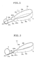
- Fig. 1 is a perspective view showing a blood vessel extroverting instrument in accordance with a first embodiment of the present invention (in a state where the diameter of a ring portion is reduced);
- Fig. 2 is a perspective view showing the blood vessel extroverting instrument in accordance with the first embodiment of the present invention (in a state where the diameter of a ring portion is increased);
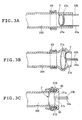
- Figs. 3A, 3B, and 3C are longitudinal sectional views of the blood vessel extroverting instrument shown in Fig. 1, for showing a sequence of steps in the method of using the instrument;
- Fig. 4 is a perspective view showing a blood vessel extroverting instrument in accordance with a second embodiment of the present invention;
- Fig. 5 is a perspective view showing a blood vessel extroverting instrument in accordance with a third embodiment of the present invention;
- Fig. 6 is a perspective view showing a blood vessel extroverting instrument in accordance with a fourth embodiment of the present invention (in a state where the outer diameter of an expanded outer configuration of a bundle of wire-like members on a distal end is increased);
- Fig. 7 is a perspective view showing the blood vessel extroverting instrument in accordance with the fourth embodiment of the present invention (in a state where the outer diameter of the expanded outer configuration of the bundle of wire-like members at the distal end is reduced); and
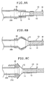
- Fig. 8A, 8B, and 8C are longitudinal sectional views of the blood vessel extroverting instrument shown in Fig. 6, for showing a sequence of steps in the method of using the instrument.
-
- A blood vessel extroverting instrument in accordance with the present invention has a contact portion to be brought into contact with an end of a blood vessel, a supporting portion on which the contact portion is supported, and an operating mechanism for changing the diameter of the contact portion. An operator can simultaneously expand and/or reverse a continuous part or at least two portions, preferably three or more portions of the end of the blood vessel in the radial direction by operating the operating mechanism.
- Blood vessel extroverting instruments which represent preferred embodiments of the present invention will be described with reference to Figs. 1 through 8. However, the blood vessel extroverting instrument of the present invention is not limited to the embodiments described below.
- Figs. 1 and 2 are perspective views of the blood vessel extroverting instrument in accordance with the first embodiment of the present invention, respectively showing a state where the diameter of a ring portion is reduced and a state where the diameter of the ring portion is increased. Figs. 3A, 3B, and 3C are longitudinal sectional views of the blood vessel extroverting instrument, showing a sequence of steps in the method of using the instrument. In Figs. 1 and 2, the ring portion is shown by being exaggerated in size relative to a supporting portion for convenience sake (the corresponding portion is also illustrated in the same manner in Figs. 4 and 5 referred to below). In the following description, the end of the blood vessel extroverting instrument on the operator's hand side will be referred to as "proximal end", the other end to be brought into contact with an end of a blood vessel when the instrument is operated will be referred to as "distal end", and the direction along which the instrument extends between the proximal end and the distal end will be referred to as "lengthwise direction".
- The blood vessel extroverting instrument indicated by 1A in Fig. 1 is used to turn an end of a blood vessel inside out. The blood vessel extroverting
instrument 1A has aring portion 2,arm portions portion 3. Thering portion 2 on the distal end is supported by thearm portions instrument 1A. The construction of each portion will be described below. - The
ring portion 2 is a portion which can be inserted into a blood vessel through the opening at an end of the blood vessel, and which is formed by curving a wire-like member into the shape of a substantially circular ring generally parallel to a plane perpendicular to the lengthwise direction. Preferablyinsertion portions ring portion 2. Theinsertion portions ring portion 2 at their ends. Theinsertion portions ring portion 2 connect to each other through two ends shown as oneend 21a and theother end 21b. - The wire-like member for forming the
ring portion 2 is doubly formed as a part of the ring portion 2 (substantially as a lower half of thering portion 2 as viewed in Fig. 1). That is, opposite end portions of the wire-like member forming thering portion 2 are in a state of intersecting each other. - Preferably, the outer diameter of the
ring portion 2 is ordinarily about 1 to 20 mm in the most contracted state, depending upon the diameter of a blood vessel to be extroverted. - It is also preferred that the outer diameter of the
ring portion 2 when reduced to the smallest value with respect to a blood vessel to be extroverted should be substantially equal to or smaller than the inside diameter of the blood vessel, and that the inside diameter of thering portion 2 when expanded to the largest value should be larger than the value of {(the outer diameter of the blood vessel) + (the thickness of the blood vessel) × 2}. - No particular limitation is imposed on selection of the material for the thus-formed
ring portion 2. For example, the material for thering portion 2 is selected from various metallic materials, such as stainless steel, aluminum and an aluminum alloy, titanium and a titanium alloy, and a nickel-titanium alloy, or from various resin materials. - Among such materials, a material substantially elastic in the range of deformation caused during use of the blood vessel extroverting
instrument 1A, for example, a superelastic material (superelastic alloy) such as a nickel-titanium alloy is preferred for thering portion 2. If thering portion 2 is formed of such a superelastic alloy, its shape close to a circle (perfect circle) can be maintained even when thering portion 2 is deformed by being changed in diameter. Also, thering portion 2 formed of such a superelastic alloy has improved durability. - No particular limitation is imposed on selection of the cross-sectional shape of the wire-like member forming the
ring portion 2. However, a shape having substantially no angular portion, e.g., a circle or an ellipse is preferred as the cross-sectional shape of the wire-like member. Preferably, the thickness (width) of the wire-like member forming thering portion 2 is ordinarily about 0.1 to 2.0 mm, depending upon the kind and the thickness of a blood vessel to be extroverted and other factors. - The supporting
portion 3 on which thering portion 2 is supported has a pair ofarm portions arm portion 31a is constituted by agrip portion 32a in the form of a plate, anend 321a of the same and theinsertion portion 33a fixed to theend 321a of thegrip portion 32a. Similarly, thearm portion 31b is constituted by agrip portion 32b in the form of a plate, anend 321b of the same and theinsertion portion 33b fixed to thegrip portion 32b. - The
insertion portions ring portion 2. Theinsertion portions ends grip portions ring portions 2 are connected to theinsertion portions end 21a and theother end 21b at the distal ends of theinsertion portions insertion portions ring portion 2 continuously through oneend 21a and theother end 21b. - Proximal ends of the
grip portions grip portions - Preferably, the
grip portions ends grip portions ring portion 2 can be automatically returned from a large-diameter state to a small-diameter state by the urging force of thegrip portions - In the thus-constructed blood
vessel extroverting instrument 1A in the unrestrained state, each of the pair ofends grip portions insertion portions end 21a and theother end 21b) of the wire-like member forming thering portion 2 are positioned apart from each other and thering portion 2 is in a small-diameter state, as shown in Fig. 1. - The operating mechanism for changing the diameter of the ring portion will now be described. The
grip portions ends grip portions insertion portions end 21a and theother end 21b) of the wire-like member forming thering portion 2 closer to each other. The diameter of thering portion 2 is thereby increased. - The blood
vessel extroverting instrument 1A of this embodiment may have a regulating means for regulating the maximum diameter (size) of thering portion 2. That is, as shown in Fig. 2, the diameter of thering portion 2 is maximized when theends grip portions ring portion 2 is regulated so as not to increase further. The maximum diameter of thering portion 2 is set to a value large enough to extrovert a blood vessel. The limiting means is used to prevent a blood vessel from being excessively expanded to be damaged. It is preferable to use the limiting means because of this effect of improving safety. - When the
grip portions ring portion 2. - In the present invention, a mechanism capable of fixing the diameter (size) of the
ring portion 2 at an arbitrary or predetermined size may be provided. The operability is thereby improved. In this embodiment, such a fixing mechanism is constituted by, for example, a regulatory means for regulating the distance between the ends of both thegrip portions - An example of the method of using the blood
vessel extroverting instrument 1A (the operation of the instrument) will next be described in detail. - (1) As shown in Fig. 3A, an end of a
blood vessel 200 is passed through aclip ring 60, and the distal end (ring portion 2,insertion portions vessel extroverting instrument 1A is inserted into theblood vessel 200 through the end opening of theblood vessel 200. When this insertion is performed, thering portion 2 is maintained in the small-diameter state (the state shown in Fig. 1). This operation is performed while theclip ring 60 is supported by, for example, being pinched between tweezers (not shown). Theclip ring 60 is not exclusively used if the blood vessel can be fixed by using, instead of theclip ring 60, a divisible pipe-shaped instrument which can be removed after the completion of extroversion, a pair of tweezers, or the like. - (2) Next, as shown in Fig. 3B, the
grip portions ring portion 2 in the large-diameter state (the state shown in Fig. 2). The portion of theblood vessel 200 positioned around thering portion 2 is thereby expanded outward. During this operation in this embodiment, oneend 21a and theother end 21b can be brought closer to each other by gripping thegrip portions ring portion 2. Thus, the instrument has improved operability. - (3) Thereafter, the
ring portion 2 is brought closer to the clip ring 60 (or theclip ring 60 is brought closer to the ring portion 2) to insert theclip ring 60 into a position inside thering portion 2 with the increased diameter. A portion of theblood vessel 200 at the end of the same is thereby turned inside out to form a turnedportion 210, with which the outer periphery of the clipping 60 is covered, as shown in Fig. 3C. Thering portion 2 is then removed from theblood vessel 200 to complete the extroverting operation. -
- Fig. 4 is a perspective view showing a blood vessel extroverting instrument in accordance with a second embodiment of the present invention.
- The blood vessel extroverting instrument of this embodiment will be described with reference to Fig. 4 mainly with respect to points of difference from the above-described embodiment. The description for the same details will not be repeated.
- The blood
vessel extroverting instrument 1B shown in Fig. 4 is used to turn an end of a blood vessel inside out, as is the bloodvessel extroverting instrument 1A, and has aring portion 4 positioned at its distal end,arm portions ring portion 2, and a supportingportion 5. The construction of each portion will be described below. - The
ring portion 4 is a portion which can be inserted into a blood vessel through the opening at an end of the blood vessel, and which is formed by curving a wire-like member into the shape of a substantially circular ring generally parallel to a plane perpendicular to the lengthwise direction. Preferablyinsertion portions ring portion 4. Theinsertion portions ring portion 4 at their ends. Theinsertion portions ring portion 4 connect to each other through two ends shown as oneend 41a and theother end 41b. - The
ring portion 4 includes no doubly-formed portions (intersecting portions) of the above-described wire-like member. Oneend 41a and theother end 41b of the wire-like member forming thering portion 4 are positioned respectively at lower positions of thering portion 4 as viewed in Fig. 4. - The supporting
portion 5 on which thering portion 4 is supported has a pair ofarm portions arm portion 51a is constituted by agrip portion 52a in the form of a plate, anend 521a of the same and theinsertion portion 53a fixed to theend 521a of thegrip portion 52a. Similarly, thearm portion 51b is constituted by agrip portion 52b in the form of a plate, anend 521b of the same and theinsertion portion 53b fixed to theend 521b of thegrip portion 52b. - Proximal ends of the
grip portions grip portions - The
grip portions portions 54 formed at intermediate positions thereof so as to intersect thegrip portions grip portion 52a is on the left-hand side of the distal end of thegrip portion 52b. Conversely, the proximal end of thegrip portion 52b is on the righthand side of the proximal end of thegrip portion 52b. - Preferably, the thus-formed
grip portions ends - The
insertion portions ends grip portions ring portion 4 is connected to theinsertion portions end 41a and theother end 41b at the distal ends of theinsertion portions - In the thus-constructed blood
vessel extroverting instrument 1B in the unrestrained state, each of the pair ofends grip portions insertion portions end 41a and theother end 41b) of the wire-like member forming thering 4 are in contact with or close to each other and thering portion 4 is in a small-diameter state, as shown in Fig. 4. - The operating mechanism for changing the diameter of the ring portion will now be described. The
grip portions ends grip portions insertion portions end 41a and theother end 41b) of the wire-like member forming thering portion 4 apart from each other. The diameter of thering portion 4 is increased to make thering portion 4 into C-shape. When the gripping force to thegrip portions grip portions - The blood
vessel extroverting instrument 1B of this embodiment may have a regulatory means 9 for regulating the maximum diameter (size) of thering portion 4. It'is preferable to provide the limiting means 9 because it enables adjustment of the maximum diameter (size) of thering portion 4. - The limiting means 9 is preferably constituted by a
hook 91 formed so as to project from theend 521b of thegrip portion 52b to a position outside theother end 521a, and astopper 92 formed of a threaded member screwed into aside plate 911 of thehook 91. - The
side plate 911 of thehook 91 is formed substantially parallel to theends grip portions end 521a of thegrip portion 52a is inserted in achannel 93 formed between theend 521b and theside plate 911. - The limiting means 9 thus provided stops the
ends grip portions end 521a of thegrip portion 52a is brought into contact with anend 921 of thestopper 92. The maximum diameter (size) of thering portion 4 is determined in correspondence with this state. This limiting means prevents a blood vessel from being excessively expanded to be damaged, as does that in the first embodiment. Thus, a further improvement in safety is achieved. - Further, it is possible to adjust the maximum diameter (size) of the
ring portion 4 to a selected value through adjustment of the maximum distance between theends grip portions stopper 92. The range of application of the instrument can be increased by adjusting the instrument in this manner to different thicknesses of blood vessels in various cases of diseases or regions to which the instrument is applied. - Various conditions, operations and effects relating to the diameter (size) and the material for the
ring portion 4 and the thickness of the wire-like member in this bloodvessel extroverting instrument 1B are the same as those in the above-described bloodvessel extroverting instrument 1A. - Fig. 5 is a perspective view of a blood vessel extroverting instrument in accordance with a third embodiment of the present invention.
- The blood vessel extroverting instrument of this embodiment will be described with reference to Fig. 5 mainly with respect to points of difference from the above-described embodiments. The description for the same details will not be repeated.
- The blood
vessel extroverting instrument 1C of this embodiment shown in Fig. 5 is used to turn an end of a blood vessel inside out, and has aring portion 6 positioned at its distal end and a supporting portion 7 on which thering portion 6 is supported. The construction of each portion will be described below. - The
ring portion 6 is formed by curving a portion of a wire-like member 8 into the shape of a substantially circular ring generally parallel to a plane perpendicular to the lengthwise direction. - The supporting portion 7 is constituted by a
grip portion 71 which can be gripped in a hand, and aninsertion portion 72 formed so as to project from an end of thegrip portion 71 to the distal end of the instrument. - The
insertion portion 72 is a slender tubular member (pipe) made of a material selected from various metallic materials, e.g., stainless steel, or a material selected from various resin materials, etc. The wire-like member 8 is passed through theinsertion portion 72. - The passage for the wire-
like member 8 formed in theinsertion portion 72 is curved (bent) (to the right as viewed in Fig. 5) to form anexternal opening 721 at the distal end of theinsertion portion 72 so that theopening 721 faces in a direction substantially perpendicular to the lengthwise direction. - A portion of the wire-
like member 8 in the vicinity of the distal end of theinsertion portion 72 extrudes from and retracts into theopening 721 in a direction substantially perpendicular to the lengthwise direction. - An
end 81 of the wire-like member 8 extending out of theopening 721 is fixed to a side portion of the distal end of theinsertion portion 72 by, for example, glueing, welding or caulking. - The portion of the wire-
like member 8 between theend 81 and theopening 721 forms thering portion 6. - An
end 82 of the wire-like member 8 on the opposite side is introduced into the interior of thegrip portion 71 through a proximal end of theinsertion portion 72 and is connected to a slider portion positioned inside thegrip portion 71 of a slider (operating portion) 73 mounted on thegrip portion 71. - The
slider 73 is mounted so as to be slidable through a predetermined range along the lengthwise direction in aslit 711 formed in thegrip portion 71. An operator can move theslider 73 along the lengthwise direction by, for example, putting his or her thumb on a portion of theslider 73 located outside thegrip portion 71. - When the
slider 73 is moved relative to thegrip portion 71 toward the distal end as indicated by the arrow in Fig. 5, the wire-like member 8 is paid out through theopening 721 to increase the length of the portion of the wire-like member 8 forming thering portion 6, thereby increasing the diameter of thering portion 6. - Conversely, when the
slider 73 is moved relative to thegrip portion 71 toward the proximal end, the wire-like member 8 retracts into theinsertion portion 72 through theopening 721 to reduce the length of the portion of the wire-like member 8 forming thering portion 6, thereby reducing the diameter of thering portion 6. - The blood
vessel extroverting instrument 1C of this embodiment may have a limiting means for limiting the maximum diameter (size) of thering portion 6. That is, when theslider 73 is brought into contact with a distal end of theslit 711, the wire-like member 8 is not further paid out through theopening 721 of theinsertion portion 72. In this state, therefore, the size of thering portion 6 is maximized and the diameter of thering portion 6 is not further increased. The regulatory means is used to prevent a blood vessel from being excessively expanded to be damaged, as is that in the above-described embodiments. It is preferable to use the regulatory means because of this effect of improving safety. - In this embodiment, it is possible to adjust the maximum diameter (size) of the
ring portion 6 to a selected value by, for example, performing variable setting of the fixed position of the end (proximal end) 82 of the wire-like member 8 relative to theslider 73. The range of application of the instrument can be increased by adjusting the instrument in this manner to different thicknesses of blood vessels in various cases of diseases or regions to which the instrument is applied. - In this embodiment, the
slider 73 may be urged in the direction of the proximal end or the distal end by, for example, connecting a spring (not shown) to theslider 73. In this manner, urging in the direction for setting thering portion 6 in the small-diameter state or large-diameter state, corresponding to the manner in the above-described embodiments, can be performed. - Also, a mechanism capable of fixing the diameter (size) of the
ring portion 6 at an arbitrary or predetermined size may be provided. Such a fixing mechanism is constituted by, for example, a positioning means for determining the position of theslider 73 relative to thegrip portion 71. - Various conditions, operations and effects relating to the diameter (size) and the material for the
ring portion 6 and the thickness of the wire-like member in this bloodvessel extroverting instrument 1C are the same as those described above with respect to the bloodvessel extroverting instrument 1A. - A blood
vessel extroverting instrument 1D shown in Figs. 6 and 7 is an instrument used to turn an end of a blood vessel inside out. The bloodvessel extroverting instrument 1D has a bundle of wire-like members 12 used as a member to be brought into contact with an end of a blood vessel, a supportingportion 13 on which the bundle of wire-like members 12 is supported, and ahollow member 14 which constitutes an operating mechanism for increasing and reducing the diameter of the distal end of the bundle of wire-like members 12. The bloodvessel extroverting instrument 1D is an instrument capable of simultaneously expanding and/or extroverting at least two portions of an end of a blood vessel in the radial direction by operating thehollow member 14 constituting the operating mechanism. - Fig. 6 is a perspective view of the blood vessel extroverting instrument in the fourth embodiment of the present invention in a state where the bundle of wire-
like members 12 is expanding radially from an end of the bundle of wire-like members 12 on the proximal end side (hereinafter referred to as "proximal end") to an end of the bundle of wire-like members 12 on the distal end side (hereinafter referred to as "distal end"). Fig. 7 is a perspective view of the blood vessel extroverting instrument shown in Fig. 6, showing a state where the distal end of the bundle of wire-like members 12 is restrained by hollow member. Fig. 8A, 8B, and 8C are longitudinal sectional views of the blood vessel extroverting instrument shown in Fig. 6, showing a sequence of steps in the method of using the instrument. In Figs. 6 and 7, the bundle of wire-like members is shown by being exaggerated in size relative to the supporting portion for convenience sake (the bundle of wire-like members is also illustrated in the same manner in Figs. 8A, 8B, and 8C referred to below). - The blood
vessel extroverting instrument 1D shown in Fig. 6 is used to turn an end of a blood vessel inside out, and has the bundle of wire-like members 12 positioned at its distal end, the supportingportion 13 on which the bundle of wire-like members 12 is supported, and thehollow member 14 capable of covering the bundle of wire-like members 12. The construction of each component will be described below. - The bundle of wire-
like members 12 is formed of two or more wire-like members. Fig. 6 illustrates a case where the bundle of wire-like members 12 is formed of four wire-like members like members portion 13 so that the distal end of the bundle of wire-like members 12 expand radially when the bundle of wire-like members 12 is not covered with thehollow member 14. - The number of wire-like members is not particularly limited as long as the number thereof is equal to or more than two. Preferably, it is three or more. It is desirable to provided two or more wire-like members in order to ensure certain facility and safety with which the operation for extroverting a blood vessel is performed.
- The placement of the wire-
like members like members member 13. - It is preferred that the distal ends of the wire-
like members like members - No particular limitation is imposed on selection of the material for the thus-formed wire-
like members - Among such materials, a material substantially elastic in the range of deformation caused during use of the instrument, for example, a superelastic material (superelastic alloy) such as a nickel-titanium alloy is preferred. If each of the wire-
like members like members 12 can be maintained even when the expanded outer configuration of the bundle of wire-like members 12 at the distal end is deformed by being increased and reduced in diameter. Also, the wire-like member formed of such a superelastic alloy has improved durability. - Preferably, the thickness of the wire-
like members - Preferably, the supporting
portion 13 on which the bundle of wire-like members 12 is supported is made of a rigid material. A material selected from various metallic materials, resin materials, etc., may be preferably used as the material for the supportingportion 13. - Fig. 7 illustrates a state where the
hollow member 14 is moved toward the distal end to reduce the outer diameter of the expanded outer configuration of the bundle of wire-like members 12 at the distal end. - The inside diameter of the
hollow member 14 is smaller than the outer diameter of the expanded distal end of the bundle of wire-like members 12. Preferably, thehollow member 14 is formed of a rigid pipe. A material selected from various metallic materials, resin materials, etc., may be preferably used as the material for thehollow member 14. - A
regulatory member 16 is provided on the supportingmember 13. Theregulatory member 16 has the function of limiting the movement of thehollow member 14 in the direction from the distal end to the proximal end of the bundle of wire-like members 12 to regulate the expansion of the bundle of wire-like members 12 at the distal end. - It is desirable that the
regulatory member 16 be mounted so as to be movable along the lengthwise direction of the supportingmember 13 to enable adjustment of the expansion of the bundle of wire-like members 12 at the distal end according to the diameter of a blood vessel to be extroverted and to thereby prevent the blood vessel from being excessively expanded. - For example, a structure for enabling the
regulatory member 16 to be mounted as described above may be realized in such a manner that theregulatory member 16 is screwed into the supportingportion 13 and a plurality of threaded holes are provided along the lengthwise direction of the supportingmember 13. Alternatively, theregulatory member 16 may be fixed at an arbitrary position in a groove formed in the supportingmember 13. - If the
regulatory member 16 for regulating the expansion of the bundle of wire-like members is provided, a blood vessel to be extroverted is prevented from being excessively expanded, thus achieving a further improvement in safety. Further, if the adjustment mechanism for adjusting the expansion of the bundle of wire-like members is provided, the range of application of the instrument can be increased by adjusting the instrument to different diameter of blood vessels in various cases of diseases or regions to which the instrument is applied. - Also, a
grip portion 15 is provided at the proximal end of the supportingportion 13 to improve the operability. Thegrip portion 15 may be formed integrally with the supportingportion 13 or may be provided as a separate member and fixed to the supportingportion 13. - An example of a method of using the blood
vessel extroverting instrument 1D (the operation of the instrument) will next be described in detail. - (1) As shown in Fig. 8A, an end of a
blood vessel 200 is passed through aclip ring 60, and the distal end (the distal end of the bundle of wire-like members 12) of the bloodvessel extroverting instrument 1D is inserted into theblood vessel 200 through the end opening of theblood vessel 200. This operation is performed while theclip ring 60 is supported by, for example, being pinched between tweezers (not shown). Before this insertion, thehollow member 14 is moved toward the distal end to maintain the bundle of wire-like members 12 in the state of having the outer diameter of the distal end reduced (the state shown in Fig. 7). - (2) Next, as shown in Fig. 8B, the
hollow member 14 is moved toward the proximal end of the bundle of wire-like members 12 to increase the outer diameter of the expanded outer configuration of the bundle of wire-like members 12 at the distal end (the state shown in Fig. 6), thereby expanding the portion of theblood vessel 200 around the bundle of wire-like members 12. - (3) Thereafter, the bundle of wire-
like members 12 is brought closer to the clip ring 60 (or theclip ring 60 is brought closer to the bundle of wire-like members 12) to move theclip ring 60 to a position inside the bundle of wire-like members 12 increased in diameter. A portion of theblood vessel 200 including the end of the same is thereby turned inside out to form a turnedportion 210, with which the periphery of the clipping 60 is covered, as shown in Fig. 8C. The bundle of wire-like members 12 is then removed from theblood vessel 200 to complete the extroverting operation. -
- The blood vessel extroverting instrument of the present invention has been described with respect to the illustrated embodiments. However, the present invention is not limited to the described embodiment. Each component constituting the blood vessel extroverting instrument can be replaced with a component of a different construction capable of performing the same function.
- For example, the mechanism for changing the diameter (size) of the ring portion is not limited to those having the illustrated constructions, and may be replaced by a mechanism of a forcipate (scissor-like) structure, a mechanism of an endoscope forcipate structure, or any of other mechanisms, such as a rotary mechanism, a link mechanism, a cam mechanism, and a gear mechanism, capable of transmitting an operating force.
- The ring portion may be arranged in such a manner that it is in the large-diameter state when the blood vessel extroverting instrument is in the unrestrained state, and its diameter is reduced when an external force (operating force) is applied to the instrument.
- The shape and structure of the ring portion are not limited to those in the illustrated embodiments as long as the ring portion has a generally circular configuration. "Generally circular configuration" denotes a category including a C-shape, an elliptical shape, a looped shape, a coiled shape, polygonal shapes, and combinations of these shapes.
- While the structures having supporting portions have been described, the arrangement may alternatively be taken such that proximal ends of wire-like members in a bundle are combined to form a portion to be used as a supporting portion and as a grip portion.
- Further, the shape and structure of each of the supporting portion and the hollow member are not limited to those in the illustrated embodiments. For example, a member having a polygonal cross-sectional configuration may be used preferably.
Claims (15)
- A blood vessel extroverting instrument used to turn an end of a blood vessel inside out, characterized in that:the blood vessel extroverting instrument comprises:a contact portion to be brought into contact with an end of a blood vessel;a supporting portion on which said contact portion is supported; andan operating mechanism for increasing and reducing the diameter of said contact portion; andthat at least two portions of the end of the blood vessel in the radial direction can be simultaneously expanded and/or reversed by operating said operating mechanism.
- A blood vessel extroverting instrument as set forth in claim 1, characterized in that:said contact portion comprises a ring portion formed of a wire-like member in the form of a substantially circular ring, said ring portion being supported on said supporting portion, and the diameter of said ring portion is increased and reduced by said operating mechanism; andthat said ring portion is inserted into the blood vessel through the opening of the end of the blood vessel while being maintained in the state of having its diameter reduced, and the diameter of said ring portion is thereafter increased.
- A blood vessel extroverting instrument according to claim 2, characterized in that: said supporting portion has a pair of arms; the wire-like member forming said ring portion is connected to distal ends of said arms; and the diameter of said ring portion is changed by changing the distance between the distal ends of said pair of arms.
- A blood vessel extroverting instrument according to claim 3, characterized in that said wire-like member or said pair of arms include intermediate portions intersecting each other.
- A blood vessel extroverting instrument according to claim 2, characterized in that the diameter of said ring portion is changed by changing the length of said wire-like member forming said ring portion.
- A blood vessel extroverting instrument according to claim 5, characterized in that the length of said wire-like member is changed by causing said wire-like member to extrude from or retract into a distal end of an insertion portion on a distal end of said supporting portion.
- A blood vessel extroverting instrument according to claim 1, characterized in that:said contact portion comprises a bundle of wire-like members extending radially from a proximal end connected to said supporting portion toward a distal end, said bundle of wire-like members being supported on said supporting portion, and an expanded outer configuration of said bundle of wire-like members at the distal end is changed by said operating mechanism; andthat said bundle of wire-like members is inserted into the blood vessel through the opening of the end of the blood vessel while being maintained in the state of having the diameter of the expanded outer configuration at the distal end reduced, and the diameter of the outer configuration of said bundle of wire-like members at the distal end is thereafter increased.
- A blood vessel extroverting instrument according to claim 7, characterized in that said operating mechanism comprises a hollow tubular member capable of covering the periphery of said bundle of wire-like members and moving along the lengthwise direction of said bundle of wire-like members.
- A blood vessel extroverting instrument according to claim 7, characterized in that:said hollow tubular member has an inside diameter smaller than the expanded outer configuration of said bundle of wire-like members at the distal end;the diameter of the expanded outer configuration of said bundle of wire-like members at the distal end is reduced by moving said hollow tubular member toward the distal end of said bundle of wire-like members; andthe diameter of the expanded outer configuration of said bundle of wire-like members at the distal end is increased by moving said hollow tubular member in the direction from the distal end to the proximal end of said bundle of wire-like members.
- A blood vessel extroverting instrument according to claim 7, further comprising a grip portion provided at a proximal end of said supporting portion.
- A blood vessel extroverting instrument according to any one of claims 1 to 10, characterized in that said contact portion is made of an elastic material or a superelastic material.
- A blood vessel extroverting instrument according to any one of claims 1 to 11, further comprising regulatory means for regulating said operating mechanism.
- A blood vessel extroverting instrument according to claim 12, characterized in that said regulatory means includes an adjustment means capable of position adjustment.
- A blood vessel extroverting instrument according to any one of claims 1 to 13, characterized in that said contact portion is in the state of having its diameter reduced when said supporting portion is in an unrestrained state, and the diameter of said contact portion is increased when said supported portion is in an urged state.
- A set of a blood vessel extroverting instrument according to any one of claims 1 to 14 and a clip ring capable of being fitted around a blood vessel.
Applications Claiming Priority (4)
| Application Number | Priority Date | Filing Date | Title |
|---|---|---|---|
| JP2000359422 | 2000-11-27 | ||
| JP2000359422A JP2002159501A (en) | 2000-11-27 | 2000-11-27 | Vascular ablation device |
| JP2001072750A JP2002272748A (en) | 2001-03-14 | 2001-03-14 | Vascular ablation device |
| JP2001072750 | 2001-03-14 |
Publications (2)
| Publication Number | Publication Date |
|---|---|
| EP1210912A2 true EP1210912A2 (en) | 2002-06-05 |
| EP1210912A3 EP1210912A3 (en) | 2003-12-17 |
Family
ID=26604617
Family Applications (1)
| Application Number | Title | Priority Date | Filing Date |
|---|---|---|---|
| EP01127428A Withdrawn EP1210912A3 (en) | 2000-11-27 | 2001-11-26 | Instrument for extroverting blood vessel |
Country Status (2)
| Country | Link |
|---|---|
| US (1) | US6979337B2 (en) |
| EP (1) | EP1210912A3 (en) |
Cited By (1)
| Publication number | Priority date | Publication date | Assignee | Title |
|---|---|---|---|---|
| EP2165651A1 (en) * | 2008-09-19 | 2010-03-24 | Sorin Biomedica Cardio S.R.L. | Surgical tool for vascular exposure and access |
Families Citing this family (22)
| Publication number | Priority date | Publication date | Assignee | Title |
|---|---|---|---|---|
| US6607541B1 (en) | 1998-06-03 | 2003-08-19 | Coalescent Surgical, Inc. | Tissue connector apparatus and methods |
| US6945980B2 (en) | 1998-06-03 | 2005-09-20 | Medtronic, Inc. | Multiple loop tissue connector apparatus and methods |
| US6641593B1 (en) | 1998-06-03 | 2003-11-04 | Coalescent Surgical, Inc. | Tissue connector apparatus and methods |
| US6613059B2 (en) | 1999-03-01 | 2003-09-02 | Coalescent Surgical, Inc. | Tissue connector apparatus and methods |
| US8118822B2 (en) | 1999-03-01 | 2012-02-21 | Medtronic, Inc. | Bridge clip tissue connector apparatus and methods |
| US6695859B1 (en) | 1999-04-05 | 2004-02-24 | Coalescent Surgical, Inc. | Apparatus and methods for anastomosis |
| US8529583B1 (en) | 1999-09-03 | 2013-09-10 | Medtronic, Inc. | Surgical clip removal apparatus |
| US6926730B1 (en) | 2000-10-10 | 2005-08-09 | Medtronic, Inc. | Minimally invasive valve repair procedure and apparatus |
| US6551332B1 (en) | 2000-03-31 | 2003-04-22 | Coalescent Surgical, Inc. | Multiple bias surgical fastener |
| US8066724B2 (en) | 2002-09-12 | 2011-11-29 | Medtronic, Inc. | Anastomosis apparatus and methods |
| US8105345B2 (en) | 2002-10-04 | 2012-01-31 | Medtronic, Inc. | Anastomosis apparatus and methods |
| US7182769B2 (en) | 2003-07-25 | 2007-02-27 | Medtronic, Inc. | Sealing clip, delivery systems, and methods |
| DE602004023302D1 (en) * | 2003-08-11 | 2009-11-05 | Wilson Cook Medical Inc | SURGICAL IMPLANT |
| US20050043749A1 (en) * | 2003-08-22 | 2005-02-24 | Coalescent Surgical, Inc. | Eversion apparatus and methods |
| US8394114B2 (en) | 2003-09-26 | 2013-03-12 | Medtronic, Inc. | Surgical connection apparatus and methods |
| US7879047B2 (en) | 2003-12-10 | 2011-02-01 | Medtronic, Inc. | Surgical connection apparatus and methods |
| AU2005296053B2 (en) | 2004-10-18 | 2011-03-10 | Covidien Lp | Compression anastomosis device and method |
| US8177836B2 (en) | 2008-03-10 | 2012-05-15 | Medtronic, Inc. | Apparatus and methods for minimally invasive valve repair |
| US8518060B2 (en) | 2009-04-09 | 2013-08-27 | Medtronic, Inc. | Medical clip with radial tines, system and method of using same |
| US8668704B2 (en) | 2009-04-24 | 2014-03-11 | Medtronic, Inc. | Medical clip with tines, system and method of using same |
| CN117503220B (en) * | 2024-01-02 | 2024-04-02 | 北京华脉泰科医疗器械股份有限公司 | Vascular diameter-adjusting device |
| CN119366993B (en) * | 2025-01-02 | 2025-03-18 | 华融科创生物科技(天津)有限公司 | Fixation device for vascular anastomosis |
Family Cites Families (12)
| Publication number | Priority date | Publication date | Assignee | Title |
|---|---|---|---|---|
| US2940452A (en) * | 1958-11-07 | 1960-06-14 | Ca Nat Research Council | Vascular evertor |
| US4470415A (en) * | 1982-08-19 | 1984-09-11 | The Johns Hopkins University | Sutureless vascular anastomosis means and method |
| US4917087A (en) * | 1984-04-10 | 1990-04-17 | Walsh Manufacturing (Mississuaga) Limited | Anastomosis devices, kits and method |
| JPS61209647A (en) * | 1985-03-14 | 1986-09-17 | 須广 久善 | Incision opening retractor for connecting blood vessel |
| US4622970A (en) * | 1985-08-29 | 1986-11-18 | The Johns Hopkins University | Vascular everting instrument |
| JPH0143057Y2 (en) | 1985-12-25 | 1989-12-14 | ||
| US4762127A (en) * | 1987-04-15 | 1988-08-09 | The Montefiore Hospital Association Of Western Pennsylvania | Apparatus and method for enlarging the ends of a vessel prior to anastomosis |
| US5486187A (en) * | 1994-01-04 | 1996-01-23 | Schenck; Robert R. | Anastomosis device and method |
| US6488692B1 (en) * | 1996-09-16 | 2002-12-03 | Origin Medsystems, Inc. | Access and cannulation device and method for rapidly placing same and for rapidly closing same in minimally invasive surgery |
| US5941896A (en) * | 1997-09-08 | 1999-08-24 | Montefiore Hospital And Medical Center | Filter and method for trapping emboli during endovascular procedures |
| WO1999065409A1 (en) * | 1998-06-10 | 1999-12-23 | Advanced Bypass Technologies, Inc. | Sutureless anastomosis systems |
| US6569178B1 (en) * | 1999-03-09 | 2003-05-27 | Olympus Optical Co., Ltd. | Ultrasonic coagulating/cutting apparatus |
-
2001
- 2001-11-26 EP EP01127428A patent/EP1210912A3/en not_active Withdrawn
- 2001-11-27 US US09/993,633 patent/US6979337B2/en not_active Expired - Fee Related
Non-Patent Citations (1)
| Title |
|---|
| None |
Cited By (1)
| Publication number | Priority date | Publication date | Assignee | Title |
|---|---|---|---|---|
| EP2165651A1 (en) * | 2008-09-19 | 2010-03-24 | Sorin Biomedica Cardio S.R.L. | Surgical tool for vascular exposure and access |
Also Published As
| Publication number | Publication date |
|---|---|
| EP1210912A3 (en) | 2003-12-17 |
| US6979337B2 (en) | 2005-12-27 |
| US20020065527A1 (en) | 2002-05-30 |
Similar Documents
| Publication | Publication Date | Title |
|---|---|---|
| US6979337B2 (en) | Instrument for extroverting blood vessel | |
| US9254128B2 (en) | Re-shapeable medical device | |
| US11596434B2 (en) | Endoscopic snare device | |
| US5792177A (en) | Forceps | |
| EP0774922B1 (en) | Wound closure device | |
| EP1718213B1 (en) | An implant for occluding a body passage | |
| EP1067872B1 (en) | Endoscopic suture system | |
| US5573542A (en) | Endoscopic suture placement tool | |
| US5830191A (en) | Flexible endoscopic surgical port | |
| US5741286A (en) | Laparoscopic instrument kit including a plurality of rigid tubes | |
| US7892249B2 (en) | Cannula for receiving surgical instruments | |
| US7294139B1 (en) | Controlled - motion endoscopic grasping instrument | |
| US20200229810A1 (en) | Suture passing device | |
| CN110225716B (en) | Suture fastener with spaced apart layers | |
| JP2002529140A (en) | Medical implant connector and method for its manufacture and installation | |
| US5904649A (en) | Organ retractors | |
| EP2025294B1 (en) | Vessel-loop and method of making same | |
| JP2026507773A (en) | Method for manufacturing a movable surgical arm in endoscopic surgery | |
| CN112261909A (en) | Suture threading device and method of use | |
| KR20210157152A (en) | Ureter Access Sheath with Length-adjustable structure | |
| US20020173802A1 (en) | Conical holder for assisting vessel eversion | |
| JP2002272748A (en) | Vascular ablation device | |
| JP2002159501A (en) | Vascular ablation device |
Legal Events
| Date | Code | Title | Description |
|---|---|---|---|
| PUAI | Public reference made under article 153(3) epc to a published international application that has entered the european phase |
Free format text: ORIGINAL CODE: 0009012 |
|
| AK | Designated contracting states |
Kind code of ref document: A2 Designated state(s): AT BE CH CY DE DK ES FI FR GB GR IE IT LI LU MC NL PT SE TR |
|
| AX | Request for extension of the european patent |
Free format text: AL;LT;LV;MK;RO;SI |
|
| PUAL | Search report despatched |
Free format text: ORIGINAL CODE: 0009013 |
|
| AK | Designated contracting states |
Kind code of ref document: A3 Designated state(s): AT BE CH CY DE DK ES FI FR GB GR IE IT LI LU MC NL PT SE TR |
|
| AX | Request for extension of the european patent |
Extension state: AL LT LV MK RO SI |
|
| 17P | Request for examination filed |
Effective date: 20040430 |
|
| AKX | Designation fees paid |
Designated state(s): AT BE CH CY DE DK ES FI FR GB GR IE IT LI LU MC NL PT SE TR |
|
| 17Q | First examination report despatched |
Effective date: 20041229 |
|
| GRAP | Despatch of communication of intention to grant a patent |
Free format text: ORIGINAL CODE: EPIDOSNIGR1 |
|
| STAA | Information on the status of an ep patent application or granted ep patent |
Free format text: STATUS: THE APPLICATION IS DEEMED TO BE WITHDRAWN |
|
| 18D | Application deemed to be withdrawn |
Effective date: 20060503 |