EP1209920A2 - Optical system of liquid crystal projector - Google Patents
Optical system of liquid crystal projector Download PDFInfo
- Publication number
- EP1209920A2 EP1209920A2 EP01125534A EP01125534A EP1209920A2 EP 1209920 A2 EP1209920 A2 EP 1209920A2 EP 01125534 A EP01125534 A EP 01125534A EP 01125534 A EP01125534 A EP 01125534A EP 1209920 A2 EP1209920 A2 EP 1209920A2
- Authority
- EP
- European Patent Office
- Prior art keywords
- color
- light
- liquid crystal
- optical system
- lights
- Prior art date
- Legal status (The legal status is an assumption and is not a legal conclusion. Google has not performed a legal analysis and makes no representation as to the accuracy of the status listed.)
- Ceased
Links
- 230000003287 optical effect Effects 0.000 title claims abstract description 75
- 239000004973 liquid crystal related substance Substances 0.000 title claims abstract description 56
- 230000010287 polarization Effects 0.000 claims abstract description 27
- 238000006243 chemical reaction Methods 0.000 claims description 11
- 230000005540 biological transmission Effects 0.000 description 2
- 210000004027 cell Anatomy 0.000 description 2
- 239000003086 colorant Substances 0.000 description 2
- 238000010586 diagram Methods 0.000 description 2
- 238000003384 imaging method Methods 0.000 description 2
- 210000003644 lens cell Anatomy 0.000 description 2
- 238000000926 separation method Methods 0.000 description 2
- 230000002708 enhancing effect Effects 0.000 description 1
- 238000005286 illumination Methods 0.000 description 1
- 230000004048 modification Effects 0.000 description 1
- 238000012986 modification Methods 0.000 description 1
- 238000002834 transmittance Methods 0.000 description 1
Images

Classifications
-
- G—PHYSICS
- G03—PHOTOGRAPHY; CINEMATOGRAPHY; ANALOGOUS TECHNIQUES USING WAVES OTHER THAN OPTICAL WAVES; ELECTROGRAPHY; HOLOGRAPHY
- G03B—APPARATUS OR ARRANGEMENTS FOR TAKING PHOTOGRAPHS OR FOR PROJECTING OR VIEWING THEM; APPARATUS OR ARRANGEMENTS EMPLOYING ANALOGOUS TECHNIQUES USING WAVES OTHER THAN OPTICAL WAVES; ACCESSORIES THEREFOR
- G03B21/00—Projectors or projection-type viewers; Accessories therefor
-
- G—PHYSICS
- G02—OPTICS
- G02B—OPTICAL ELEMENTS, SYSTEMS OR APPARATUS
- G02B27/00—Optical systems or apparatus not provided for by any of the groups G02B1/00 - G02B26/00, G02B30/00
- G02B27/10—Beam splitting or combining systems
- G02B27/14—Beam splitting or combining systems operating by reflection only
- G02B27/145—Beam splitting or combining systems operating by reflection only having sequential partially reflecting surfaces
-
- G—PHYSICS
- G02—OPTICS
- G02B—OPTICAL ELEMENTS, SYSTEMS OR APPARATUS
- G02B27/00—Optical systems or apparatus not provided for by any of the groups G02B1/00 - G02B26/00, G02B30/00
- G02B27/10—Beam splitting or combining systems
- G02B27/1006—Beam splitting or combining systems for splitting or combining different wavelengths
- G02B27/102—Beam splitting or combining systems for splitting or combining different wavelengths for generating a colour image from monochromatic image signal sources
- G02B27/1026—Beam splitting or combining systems for splitting or combining different wavelengths for generating a colour image from monochromatic image signal sources for use with reflective spatial light modulators
-
- H—ELECTRICITY
- H04—ELECTRIC COMMUNICATION TECHNIQUE
- H04N—PICTORIAL COMMUNICATION, e.g. TELEVISION
- H04N9/00—Details of colour television systems
- H04N9/12—Picture reproducers
- H04N9/31—Projection devices for colour picture display, e.g. using electronic spatial light modulators [ESLM]
- H04N9/3102—Projection devices for colour picture display, e.g. using electronic spatial light modulators [ESLM] using two-dimensional electronic spatial light modulators
- H04N9/3105—Projection devices for colour picture display, e.g. using electronic spatial light modulators [ESLM] using two-dimensional electronic spatial light modulators for displaying all colours simultaneously, e.g. by using two or more electronic spatial light modulators
Definitions
- This invention relates to a liquid crystal projector, and more particularly to an optical system of a liquid crystal projector that is capable of minimizing the size and the number of optical elements of an optical system using three reflective liquid crystal displays.
- the flat panel display includes a projector that projects a small-field picture onto a large screen on an expanded scale.
- the projector employs a cathode ray tube or a liquid crystal display (LCD) as a display device for implementing a small-field picture.
- LCD liquid crystal display
- a liquid crystal projector adopts a transmissive or reflective LCD.
- the liquid crystal projector has been developed with intent to obtain small bulk, low weight and high brightness, whereas an LCD panel has been developed with intent to obtain high aperture ratio and high resolution.
- the reflective LCD panel so as to keep up with a recent trend toward a liquid crystal projector realizing high resolution, small bulk and low cost.
- the liquid crystal projector takes advantage of a light emitting from a light source to implement a picture on the LCD panel.
- the liquid crystal projector images a picture of the LCD panel onto a screen using a projective optical system to observe a picture imaged on the screen.
- a projection distance should be assured between the screen and the projective optical system. Accordingly, since the rear side of the screen requires a relatively large space to enlarge a thickness of the projector, it is difficult to obtain a thin thickness of the projector.
- a reflecting mirror is introduced between the screen and the projective optical system to change a light path, thereby reducing a thickness of the projector.
- an arrangement angle of the reflecting mirror has to be more than a critical angle thereof so as to project a picture onto the rear screen without any distortion, there is a limit in reducing a thickness of the system.
- there is a limit in reducing a thickness of the system due to an inherent full length of an optical system consisting of an illumination system, the LCD and the projective lens system of the projector.
- the liquid crystal projector includes first and second fly eye lenses (FEL's) 6 and 8, a polarizing beam splitter (PBS) array 10 and a first condensing lens 12 arranged between a light source 4 and a full-reflecting mirror 14, and a second condensing lens 16 arranged between the full-reflecting mirror 14 and a first Dichroic mirror 18.
- FEL's fly eye lenses
- PBS polarizing beam splitter
- a white color light emitting from a lamp of the light source 4 is reflected by a parabolic mirror to be progressed toward the first FEL 6.
- the first FEL 6 divides an incident light into the cell units and allows them to be focused onto each lens cell of the second FEL 8.
- the second FEL 8 converts an incident light into a parallel light for a specific portion and transmits the same to the PBS array 10.
- the PBS array 10 separates an incident light into linear polarized lights having any one light axis, that is, a P-polarized light and a S-polarized light.
- a half wavelength plate partially attached to the rear side of the PBS array 10 converts the transmitted P-polarized light into a S-polarized light.
- all incident lights are converted into S-polarized lights by means of the PBS array 10, thereby permitting most lights emitting from the light source 4 to be incident to picture implementing elements 26R, 26G and 26B of the LCD panel.
- the first condensing lens 12 focuses an incident light from the PBS array 10 onto the full-reflecting mirror 14.
- the full-reflecting mirror 14 makes a full reflection of an incident light from the first condensing lens 12 and allows the same to be progressed toward the second condensing lens 16.
- the second condensing lens 16 focuses an incident light from the full-reflecting mirror 14 onto the first Dichroic mirror 18.
- the first Dichroic mirror 18 transmits a light at a blue color area in the incident lights while reflecting lights at a green color area and at a red color area having a larger wavelength than a blue light.
- the optical system of the liquid crystal projector shown in Fig. 1 includes a second Dichroic mirror 20, a first polarizing film 22R and a first polarizing beam splitter prism (PBSP) 24R arranged between the first Dichroic mirror 18 and the red LCD panel 26R, a second polarizing film 22G and a second PBSP 24G arranged between the second Dichroic mirror 20 and the green LCD panel 26G, a first relay lens 27, a second full-reflecting mirror 28, a second relay lens 29, a third polarizing film 22B and a third PBSP 24B arranged between the first Dichroic mirror 18 and the blue LCD panel 26B, a Dichroic prism 30 arranged among the first to third PBSP's 24R, 24G and 24B, and a projection lens 32 installed in opposition to an light output surface of the Dichroic prism 30.
- PBSP polarizing beam splitter prism
- the second Dichroic mirror 20 reflects a light at the blue area in lights reflected from the first Dichroic mirror 18 and being incident thereto to progress it toward the second polarizing film 22G while transmitting a light a the red area to progress it toward the first polarizing film 22R.
- the second full-reflecting mirror 28 reflects a light at the blue area transmitted from the first Dichroic mirror 18 and being incident thereto to progress it toward the third polarizing film 22B.
- the first and second relay lenses 27 and 29 are field lenses, which relay an imaging point of a light at the blue area to re-image the blue light onto the blue LCD panel 26B.
- Each of the first to third polarizing films 22R, 22G and 22B transmits only a S-polarized light parallel to its optical axis in the incident lights and allows it to be progressed toward the first to third PBSP's 24R, 24G and 24B, respectively.
- the first to third PBSP's 24R, 24G and 24B reflects red, green and blue S-polarized lights transmitted from the first to third polarizing films 22R, 22G and 22B and being incident thereto and allows them to be progressed into the red, green and blue LCD panels 26R, 26G and 26B, respectively. Further, the first to third PBSP's 24R, 24G and 24B obtain picture information from the red, green and blue LCD panel 26R, 26G and 26B to transmit red, green and blue lights converted into P-polarized lights, respectively and allows them to be progressed toward the Dichroic prism 30.
- Each of the red, green and blue LCD panels 26R, 26G and 26B is a reflective LCD panel, which converts a S-polarized light reflected from each of the first to third PBSP 24R, 24G and 24B and being incident thereto into a P-polarized light to thereby implement a picture.
- the Dichroic prism 30 obtains picture information from the red, green and blue LCD panels 26R, 26G and 26B to combine the incident red, green and blue lights and output the combined light to the projection lens 32.
- First and second polarization converting films (not shown) for converting P-polarized lights from the first and third PBSP's 24R and 24B into S-polarized lights are arranged between the first and third PBSP's 24R and 24B and the Dichroic prism 30, respectively. Accordingly, the Dichroic prism 30 reflects red and blue lights having a S-polarization component being inputted via the first and second polarization converting films into the projection lens 32.
- the Dichroic prism 30 transmits a red light having a P-polarization component inputted via the second PBSP 24G into the projection lens 32, to thereby combine the red, green and blue lights.
- the projection lens 32 magnifies a picture being inputted from the Dichroic prism 30 and projects it onto the screen.
- the conventional liquid crystal projector having as described above requires a plurality of Dichroic mirrors to separate a white light from the light source into red, green and blue colors because of an adoption of three LCD panels. Also, since the conventional liquid crystal projector uses a reflective LCD panel, it requires a plurality of PBSP's differentiating paths of input and output lights on a basis of that reflective LCD panel. As an optical system of the conventional liquid crystal projector employing three reflective LCD panels requires a large number of optical elements, the size of the optical system is enlarged. Particularly, since the optical system has an inherent full length L, it has a limit in reducing a thickness thereof proportional to said inherent full length L. Thus, it becomes difficult to realize a thin thickness of the optical system.
- an optical system that has a two-layer structure in which a color separator is arranged at the upper layer of the color-combining part and the projecting lens system so as to reduce a full length L of the optical system.
- the two-layer structure optical system also employs a large number of optical elements to have a limit in reducing its size.
- an object of the present invention to provide an optical system of a liquid crystal projector that is capable of reducing the number of optical elements as well as the size of the optical system.
- an optical system of a liquid crystal projector includes an illuminating unit for allowing a white light generated from a light source to have any one linear polarized light and a uniform light distribution; a color separator for separating the white light from the illuminating unit in accordance with a wavelength band to obtain a first color light and for polarization-converting the remaining lights in accordance with a wavelength band and then separating them into second and third color lights depending on their polarization components; first to third liquid crystal display panels using the first to third color lights from the color separator to implement first to third color pictures, respectively; a picture combining unit for combining the first to third color lights having acquired picture information from the first to third liquid crystal display panels; and a projection lens unit for projecting the combined picture from the picture combining unit onto a screen on an expanded scale.
- the color separator includes a first Dichroic mirror for separating the white light in accordance with a wavelength band and allowing the separated first color light to be progressed toward the first liquid crystal display panel; and a first color selector for polarization-converting the remaining lights from the first Dichroic mirror in accordance with a wavelength band to differentiate polarization components of the second and third color lights.
- the optical system further includes a first polarized light separating prism for separating the second and third color lights from the first color selector in accordance with a polarization direction and allowing them to be progressed toward the second and third liquid crystal display panels, respectively.
- each of said first to third liquid crystal display panels is a reflective liquid crystal display panel for converting and outputting a polarization component of an incident light depending on the picture information; and said first polarized light separating prism for allowing the second and third color lights polarization-converted by acquiring picture information from the second and third liquid crystal display panels to be progressed into the picture combining unit.
- the optical system further includes a second polarized light separating prism for allowing the first color light from the Dichroic mirror to be incident to the first liquid crystal display panel and allowing the first color light polarization-converted by acquiring picture information from the first liquid crystal display panel to be progressed toward the picture combining unit.
- the picture combining unit further includes any one of a third polarized light separating prism and a Dichroic prism for acquiring picture information from the first to third liquid crystal display panels to combine the first to third color lights being incident thereto via the first and second polarized light separating prisms and output the combined light.
- the picture combining unit further includes a second color selector for selectively converting polarization components of the second and third color lights outputted from the first polarizing prism in accordance with a wavelength band and allowing it to be progressed toward any one of the third polarized light separating prism and the Dichroic prism in the same linear polarized state.
- the first and second color selectors make a polarization conversion of the red light while transmitting the light at other wavelength band as it is.
- the optical system further includes a half wavelength plate for converting a linear polarized light of the first color light having acquired the picture information from the second polarizing prism and allowing it to be progressed toward any one of the third polarized light separating prism and the Dichroic prism.
- the optical system further includes a third color selector for polarization-converting the combined picture from the picture combining unit in accordance with a wavelength band and allowing it to be progressed toward the projection lens.
- the third color selector allows all lights going between the picture combining unit and the projection lens unit to be converted into P-polarized lights.
- the picture combining unit includes a second Dichroic mirror for selectively reflecting and transmitting the first to third color lights from the first and second polarized light separating prisms in accordance with a wavelength band to combine a picture.
- the optical system further includes first and second color light filters arranged between the second and third liquid crystal display panels and the first polarized light separating prism, respectively to enhance color purity.
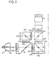
- FIG. 2 there is shown an optical system of a liquid crystal projector according to an embodiment of the present invention.
- the optical system includes three reflective LCD panels 46R, 46G and 46B for displaying a picture, an illuminating unit for allowing a white light from a light source 30 to be uniformly and efficiently irradiated onto the LCD panels 46R, 46G and 46B, a color separator for spatially separating a white light from the illuminating unit into red, green and blue color lights and allowing the separated color lights to be the reflective LCD panels 46R, 46G and 46B, a light combining unit for combining three color lights obtaining picture information from the reflective LCD panels 46R, 46G and 46B, and a projection lens 50 for magnifying and projecting the combined picture.
- the illuminating unit consists of the light source 30, first and second FEL's 32A and 32B and a PBS array 34.
- the color separator includes a Dichroic mirror 38, a first color-selective polarization-converting device 42, hereinafter referred to as "color selector" for making a polarization conversion in accordance with a wavelength area, and a first PBSP 44A.
- the light combining unit consists of said first PBSP 44A, a second PBSP 44B, a second color selector 42B and a third PBSP 44C.
- a white color light emitting from the light source 30 goes toward the first FEL 32A.
- the first FEL 32A divides an incident light into the cell units and allows them to be focused onto each lens cell of the second FEL 32B.
- the second FEL 32B converts an incident light into a parallel light for a specific portion.
- the PBS array 34 is integral to the second FEL 32B to separate an incident light into a P-polarized light and a S-polarized light. Then, a half wavelength ( ⁇ /2) plate (not shown) partially attached to the rear side of the PBS array 34 converts the transmitted P-polarized light into a S-polarized light.
- the first condensing lens 36A focuses an incident light.
- Such an illuminating unit converts all incident lights into a linear polarized light in any one direction, that is, a S-polarized light in such a manner to be uniformly incident to the LCD panels 46R, 46G and 46B, thereby improving a light efficiency.
- the first Dichroic mirror 38 selectively reflects or transmits an incident light from the illuminating unit in a wavelength area. For instance, the first Dichroic mirror 38 transmits a light at a blue color area in the incident lights while reflecting lights at a green color area and at a red color area having a larger wavelength than said light at the blue color area.
- the first color selector 42A make a selective polarization conversion of lights at the red and green areas transmitting the first Dichroic mirror 38 and being incident thereto in accordance with a wavelength area. For instance, the first color selector 42A rotates a light at the blue area at 90° to convert a S-polarized light into a P-polarized light while transmitting a light at the red area with keeping a S-polarization state as it is.
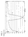
- the first color selector 42A is most preferably designed such that it makes a polarization conversion of a red light R having a good transmittance characteristic after polarization conversion as can be seen from a transmission characteristic diagram of the color selector shown in Fig. 3.
- Such a first color selector 42A making a selective polarization conversion according to a wavelength area has been disclosed in U.S. Patent No. 5,990, 996.
- a transmitted light output side and a reflected light output side of the Dichroic mirror 38 are further provided with condensing lenses 36B and 36C and S polarizers 40A and 40B, respectively.
- the condensing lenses 36B and 36C focuses a light and the S polarizers 40A and 40B, thereby enhancing a purity of the S-polarized light.
- the first PBSP 44A transmits a P-polarized light at the red area polarization-converted by means of the first color selector 42A and being incident thereto toward the red LCD panel 46R while reflecting a S-polarized light at the green area being incident thereto as it is into the red LCD panel 46G. Further, the first PBSP 44A reflects a S-polarized light at the red area polarization-converted by acquiring picture information from the red LCD panel 46R and being incident thereto into the third PBSP 44C while transmitting a P-polarized light at the green area polarization-converted by acquiring picture information from the red LCD panel 46G and being incident thereto toward the third PBSP 44C.
- the second PBSP 44B reflects a S-polarized light at the blue area reflected from the Dichroic mirror 38 and being incident thereto into the blue LCD panel 46B while transmitting a blue light converted into a P-polarized light by acquiring picture information from the blue LCD panel 46B toward the third PBSP 44C.
- Each of the red, green and blue LCD panels 46R, 46G and 46B is a reflective LCD panel, which polarization-converts and outputs a line-polarized light being incident thereto to implement the corresponding color picture.
- the transmitted light output side of the second PBSP 44B is further provided with a P polarizer 40C and a half wavelength ( ⁇ /2) plate 48.
- the P polarizer 40C transmits only a P-polarized light to enhance a purity of a P-polarized light acquiring green picture information.
- the half wavelength plate 48 converts an incident P-polarized light into a S-polarized light.
- the second color selector 42B selectively polarization-converts an incident light from the first PBSP 44A in accordance with a wavelength area in similarity to the fore-mentioned first color selector 42A. More specifically, the second color selector 42B transmits a green P-polarized light acquiring picture information as it is while rotating a red S-polarized light acquiring picture information at 90° to output it as a P-polarized light.
- the third PBSP 44C combines incident red, green and blue lights acquiring picture information and output them to a projection lens unit 50.
- the third PBSP 44C reflects a blue light converted into a S-polarized light by means of the half wavelength plate 48 and being incident thereto into the projection lens 50 while transmitting a red light converted into a P-polarized light by means of the second color selector 42B and being incident thereto and a green light being incident thereto without any polarization conversion toward the projection lens 50.
- the third PBSP 44C can be replaced by a Dichroic prism.
- the projection lens 50 projects the combined picture inputted from the third PBSP 44C onto the screen on an expanded scale.
- the optical system of the liquid crystal projector employs the color selectors for making a selective polarization conversion according to a wavelength area, to thereby reduce the number of PBSP's differentiating paths of input and output lights of the Dichroic mirrors for a light separation and the LCD panels. Accordingly, it can reduce the number of optical elements and the size of optical system.
- the present optical system is capable of more reducing a full length L' of the optical system than a full length L of the conventional optical system shown in Fig. 1, to thereby reduce the thickness of the liquid crystal projector.
- the optical system of the liquid crystal projector according to the embodiment of the present invention further includes a third color selector 42C between the third PBSP 44C and the projection lens 50 so as to allow polarization components of all lights being incident to the projection lens unit 50 to be a P wave.
- the third color selector 42C rotates only a blue S-polarized light reflected from the third PBSP 44C and being incident thereto at 90° to convert it into a P wave while transmitting red and green P-polarized lights going through the third PBSP 44C as it is.
- a P-polarization screen transmitting only a P-polarized light is applied to the projective screen for allowing polarization components of all lights being incident to the projection lens 50 to be consistently P-polarized lights and imaging a picture enlarged by means of the projection lens 50, it becomes possible to improve a contrast of picture. Because the P polarizer adopted for the projective screen can absorb an external light.
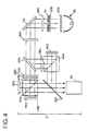
- FIG. 4 there is shown an optical system of a liquid crystal projector according to another embodiment of the present invention.
- the optical system of Fig. 4 uses a second Dichroic mirror 38B, instead of the third PBSP 44C, as a combining unit, and further includes green and red color filters 54A and 54B provided between the red and green LCD panels 46R and 46G and the second PBSP 44B to enhance a color purity and a full-reflecting mirror 52 provided between the light source 30 and the first Dichroic mirror 38A to change a light path.
- the optical system shown in Fig. 4 excludes the polarizing filters 40A, 40B and 40C, but may additionally include them.
- a detailed explanation as to elements of the optical system of Fig. 4 identical to the optical system shown in Fig. 2 will be omitted.
- First and second FEL's 32A and 32B, a PBS array 34 and first and second condensing lenses 36A and 36B allow a white light from the light source 30 to be uniformly and efficiently irradiated onto red, green and blue LCD panels 46R, 46G and 46B.
- the full-reflecting mirror 52 full-reflects an incident light from the first condensing lens 36A to progress it toward the second condensing lens 36B.
- a first Dichroic mirror 38A reflects a S-polarized light at the blue color area and allows it to be irradiated, via a third condensing lens 36C and a first PBSP 44A, onto the blue LCD panel 46B. Further, the first Dichroic mirror 38A transmits S-polarized lights at the red and green color area having a larger wavelength than a light at the blue color area and allows them to be incident to the red and green LCD panels 46R and 46G via a first color selector 42A, a fourth condensing lens 36D and a second PBSP 44A.
- the first color selector 42A rotates a S-polarized light at the blue area at 90° as mentioned above to convert it into a P-polarized light, thereby allowing it to be transmitted to the second PBSP 44B and to be incident to the red LCD panel 46R. Further, the first color selector 42A transmits a light at the green area with keeping a S-polarized light as it is, thereby allowing it to be reflected from the second PBSP 44B and to be incident to the green LCD panel 46G.
- the red and green color filters 54A and 54B installed at the second PBSP 44B in opposition to the red and green LCD panels 46R and 46G improve purities of red and green colors, respectively.
- the second Dichroic mirror 38B transmits a red light converted into a S-polarized light by acquiring picture information from the red LCD panel 46R and being incident thereto and a green light converted into a P-polarized light by acquiring picture information from the green LCD panel 46G and being incident thereto toward the projection lens 50. Further, the second Dichroic mirror 38B reflects a blue light converted into a P-polarized light by acquiring picture information from the blue LCD panel 46B and being incident thereto into the projection lens 50. As described above, the second Dichroic mirror 38B combines red, green and blue lights acquiring picture information and allows the combined light to be progressed toward the projection lens 50.
- the projection lens unit 50 projects the combined picture inputted from the second Dichroic mirror 38B onto the screen on an expanded scale.
- the optical system of the liquid crystal projector employs the color selectors for making a selective polarization conversion according to a wavelength area, to thereby reduce the number of Dichroic mirrors for a light separation and the number of PBSP's for a light combination. Accordingly, it can reduce the number of optical elements and the size of optical system.
- the present optical system is capable of more reducing a full length L" of the optical system than a full length L of the conventional optical system shown in Fig. 1, to thereby reduce the thickness of the liquid crystal projector.
- the color selectors for making a polarization conversion according to a wavelength are used to the number of optical elements such as the Dichroic mirror and the PBSP, so that it becomes possible to simplify the optical system and thus reduce the size of the optical system. Particularly, a full length of the optical system of the liquid crystal projector can be reduced to make the projector having a thin thickness.
- the P-polarization screen is adopted and the color selectors convert all light being incident to the projection lens unit into P-polarized lights, so that it becomes possible to improve a contrast of picture.
Landscapes
- Physics & Mathematics (AREA)
- General Physics & Mathematics (AREA)
- Optics & Photonics (AREA)
- Engineering & Computer Science (AREA)
- Multimedia (AREA)
- Signal Processing (AREA)
- Projection Apparatus (AREA)
- Liquid Crystal (AREA)
Abstract
Description
- This invention relates to a liquid crystal projector, and more particularly to an optical system of a liquid crystal projector that is capable of minimizing the size and the number of optical elements of an optical system using three reflective liquid crystal displays.
- Nowadays, there has been highlighted a flat panel display that is capable of replacing a cathode ray tube display having a limit in the size of screen and a large system size and realizing both a thin thickness and a large-scale screen. The flat panel display includes a projector that projects a small-field picture onto a large screen on an expanded scale.
- The projector employs a cathode ray tube or a liquid crystal display (LCD) as a display device for implementing a small-field picture. Recently, there has been mainly used the LCD to keep up with a trend toward a thin thickness of the projector. Generally, a liquid crystal projector adopts a transmissive or reflective LCD. The liquid crystal projector has been developed with intent to obtain small bulk, low weight and high brightness, whereas an LCD panel has been developed with intent to obtain high aperture ratio and high resolution. Thus, there has been used the reflective LCD panel so as to keep up with a recent trend toward a liquid crystal projector realizing high resolution, small bulk and low cost.
- The liquid crystal projector takes advantage of a light emitting from a light source to implement a picture on the LCD panel. The liquid crystal projector images a picture of the LCD panel onto a screen using a projective optical system to observe a picture imaged on the screen. When the projector is implemented by directly projecting a picture of the LCD panel onto a rear screen, a projection distance should be assured between the screen and the projective optical system. Accordingly, since the rear side of the screen requires a relatively large space to enlarge a thickness of the projector, it is difficult to obtain a thin thickness of the projector.
- In order to solve this problem, a reflecting mirror is introduced between the screen and the projective optical system to change a light path, thereby reducing a thickness of the projector. However, since an arrangement angle of the reflecting mirror has to be more than a critical angle thereof so as to project a picture onto the rear screen without any distortion, there is a limit in reducing a thickness of the system. Also, there is a limit in reducing a thickness of the system due to an inherent full length of an optical system consisting of an illumination system, the LCD and the projective lens system of the projector.
- Referring to Fig. 1, there is shown an optical system of a conventional liquid crystal projector. The liquid crystal projector includes first and second fly eye lenses (FEL's) 6 and 8, a polarizing beam splitter (PBS)
array 10 and afirst condensing lens 12 arranged between a light source 4 and a full-reflectingmirror 14, and a second condensinglens 16 arranged between the full-reflectingmirror 14 and a firstDichroic mirror 18. - A white color light emitting from a lamp of the light source 4 is reflected by a parabolic mirror to be progressed toward the
first FEL 6. Thefirst FEL 6 divides an incident light into the cell units and allows them to be focused onto each lens cell of thesecond FEL 8. Thesecond FEL 8 converts an incident light into a parallel light for a specific portion and transmits the same to thePBS array 10. ThePBS array 10 separates an incident light into linear polarized lights having any one light axis, that is, a P-polarized light and a S-polarized light. Then, a half wavelength plate (not shown) partially attached to the rear side of thePBS array 10 converts the transmitted P-polarized light into a S-polarized light. Thus, all incident lights are converted into S-polarized lights by means of thePBS array 10, thereby permitting most lights emitting from the light source 4 to be incident to picture implementingelements - The first
condensing lens 12 focuses an incident light from thePBS array 10 onto the full-reflectingmirror 14. The full-reflectingmirror 14 makes a full reflection of an incident light from the firstcondensing lens 12 and allows the same to be progressed toward the secondcondensing lens 16. The secondcondensing lens 16 focuses an incident light from the full-reflectingmirror 14 onto the firstDichroic mirror 18. The first Dichroicmirror 18 transmits a light at a blue color area in the incident lights while reflecting lights at a green color area and at a red color area having a larger wavelength than a blue light. - Further, the optical system of the liquid crystal projector shown in Fig. 1 includes a second
Dichroic mirror 20, a first polarizingfilm 22R and a first polarizing beam splitter prism (PBSP) 24R arranged between the firstDichroic mirror 18 and the red LCD panel 26R, a second polarizingfilm 22G and asecond PBSP 24G arranged between the secondDichroic mirror 20 and thegreen LCD panel 26G, afirst relay lens 27, a second full-reflectingmirror 28, asecond relay lens 29, a third polarizingfilm 22B and athird PBSP 24B arranged between the first Dichroicmirror 18 and theblue LCD panel 26B, a Dichroicprism 30 arranged among the first to third PBSP's 24R, 24G and 24B, and aprojection lens 32 installed in opposition to an light output surface of the Dichroicprism 30. - The second
Dichroic mirror 20 reflects a light at the blue area in lights reflected from the firstDichroic mirror 18 and being incident thereto to progress it toward the second polarizingfilm 22G while transmitting a light a the red area to progress it toward the first polarizingfilm 22R. The second full-reflecting mirror 28 reflects a light at the blue area transmitted from the first Dichroicmirror 18 and being incident thereto to progress it toward the third polarizingfilm 22B. - The first and
second relay lenses blue LCD panel 26B. Each of the first to third polarizingfilms - The first to third PBSP's 24R, 24G and 24B reflects red, green and blue S-polarized lights transmitted from the first to third polarizing
films blue LCD panels blue LCD panel prism 30. - Each of the red, green and
blue LCD panels third PBSP - The Dichroic
prism 30 obtains picture information from the red, green andblue LCD panels projection lens 32. First and second polarization converting films (not shown) for converting P-polarized lights from the first and third PBSP's 24R and 24B into S-polarized lights are arranged between the first and third PBSP's 24R and 24B and the Dichroicprism 30, respectively. Accordingly, the Dichroicprism 30 reflects red and blue lights having a S-polarization component being inputted via the first and second polarization converting films into theprojection lens 32. At the same time, the Dichroicprism 30 transmits a red light having a P-polarization component inputted via thesecond PBSP 24G into theprojection lens 32, to thereby combine the red, green and blue lights. Theprojection lens 32 magnifies a picture being inputted from the Dichroicprism 30 and projects it onto the screen. - The conventional liquid crystal projector having as described above requires a plurality of Dichroic mirrors to separate a white light from the light source into red, green and blue colors because of an adoption of three LCD panels. Also, since the conventional liquid crystal projector uses a reflective LCD panel, it requires a plurality of PBSP's differentiating paths of input and output lights on a basis of that reflective LCD panel. As an optical system of the conventional liquid crystal projector employing three reflective LCD panels requires a large number of optical elements, the size of the optical system is enlarged. Particularly, since the optical system has an inherent full length L, it has a limit in reducing a thickness thereof proportional to said inherent full length L. Thus, it becomes difficult to realize a thin thickness of the optical system.
- Accordingly, there has been suggested an optical system that has a two-layer structure in which a color separator is arranged at the upper layer of the color-combining part and the projecting lens system so as to reduce a full length L of the optical system. However, the two-layer structure optical system also employs a large number of optical elements to have a limit in reducing its size.
- Accordingly, it is an object of the present invention to provide an optical system of a liquid crystal projector that is capable of reducing the number of optical elements as well as the size of the optical system.
- In order to achieve these and other objects of the invention, an optical system of a liquid crystal projector according to an embodiment of the present invention includes an illuminating unit for allowing a white light generated from a light source to have any one linear polarized light and a uniform light distribution; a color separator for separating the white light from the illuminating unit in accordance with a wavelength band to obtain a first color light and for polarization-converting the remaining lights in accordance with a wavelength band and then separating them into second and third color lights depending on their polarization components; first to third liquid crystal display panels using the first to third color lights from the color separator to implement first to third color pictures, respectively; a picture combining unit for combining the first to third color lights having acquired picture information from the first to third liquid crystal display panels; and a projection lens unit for projecting the combined picture from the picture combining unit onto a screen on an expanded scale.
- In the optical system, the color separator includes a first Dichroic mirror for separating the white light in accordance with a wavelength band and allowing the separated first color light to be progressed toward the first liquid crystal display panel; and a first color selector for polarization-converting the remaining lights from the first Dichroic mirror in accordance with a wavelength band to differentiate polarization components of the second and third color lights. The optical system further includes a first polarized light separating prism for separating the second and third color lights from the first color selector in accordance with a polarization direction and allowing them to be progressed toward the second and third liquid crystal display panels, respectively.
- Particularly, each of said first to third liquid crystal display panels is a reflective liquid crystal display panel for converting and outputting a polarization component of an incident light depending on the picture information; and said first polarized light separating prism for allowing the second and third color lights polarization-converted by acquiring picture information from the second and third liquid crystal display panels to be progressed into the picture combining unit. The optical system further includes a second polarized light separating prism for allowing the first color light from the Dichroic mirror to be incident to the first liquid crystal display panel and allowing the first color light polarization-converted by acquiring picture information from the first liquid crystal display panel to be progressed toward the picture combining unit.
- In the optical system, the picture combining unit further includes any one of a third polarized light separating prism and a Dichroic prism for acquiring picture information from the first to third liquid crystal display panels to combine the first to third color lights being incident thereto via the first and second polarized light separating prisms and output the combined light.
- The picture combining unit further includes a second color selector for selectively converting polarization components of the second and third color lights outputted from the first polarizing prism in accordance with a wavelength band and allowing it to be progressed toward any one of the third polarized light separating prism and the Dichroic prism in the same linear polarized state.
- In the optical system, the first and second color selectors make a polarization conversion of the red light while transmitting the light at other wavelength band as it is.
- The optical system further includes a half wavelength plate for converting a linear polarized light of the first color light having acquired the picture information from the second polarizing prism and allowing it to be progressed toward any one of the third polarized light separating prism and the Dichroic prism.
- The optical system further includes a third color selector for polarization-converting the combined picture from the picture combining unit in accordance with a wavelength band and allowing it to be progressed toward the projection lens.
- Herein, if a P-polarization screen for transmitting only a P-polarized light is applied to said screen, then the third color selector allows all lights going between the picture combining unit and the projection lens unit to be converted into P-polarized lights.
- In example of another system, the picture combining unit includes a second Dichroic mirror for selectively reflecting and transmitting the first to third color lights from the first and second polarized light separating prisms in accordance with a wavelength band to combine a picture.
- The optical system further includes first and second color light filters arranged between the second and third liquid crystal display panels and the first polarized light separating prism, respectively to enhance color purity.
- These and other objects of the invention will be apparent from the following detailed description of the embodiments of the present invention with reference to the accompanying drawings, in which:
- Fig. 1 is a plan view showing a configuration of an optical system of a conventional liquid crystal projector;
- Fig. 2 is a plan view showing a configuration of an optical system of a liquid crystal projector according to an embodiment of the present invention;
- Fig. 3 is a transmission characteristic diagram of the first color selector shown in Fig. 2; and
- Fig. 4 is a plan view showing a configuration of an optical system of a liquid crystal projector according to another embodiment of the present invention.
-
- Referring to Fig. 2, there is shown an optical system of a liquid crystal projector according to an embodiment of the present invention.
- The optical system includes three
reflective LCD panels light source 30 to be uniformly and efficiently irradiated onto theLCD panels reflective LCD panels reflective LCD panels projection lens 50 for magnifying and projecting the combined picture. - The illuminating unit consists of the
light source 30, first and second FEL's 32A and 32B and aPBS array 34. The color separator includes aDichroic mirror 38, a first color-selective polarization-converting device 42, hereinafter referred to as "color selector" for making a polarization conversion in accordance with a wavelength area, and afirst PBSP 44A. The light combining unit consists of saidfirst PBSP 44A, asecond PBSP 44B, asecond color selector 42B and athird PBSP 44C. - A white color light emitting from the
light source 30 goes toward thefirst FEL 32A. Thefirst FEL 32A divides an incident light into the cell units and allows them to be focused onto each lens cell of thesecond FEL 32B. Thesecond FEL 32B converts an incident light into a parallel light for a specific portion. ThePBS array 34 is integral to thesecond FEL 32B to separate an incident light into a P-polarized light and a S-polarized light. Then, a half wavelength (λ/2) plate (not shown) partially attached to the rear side of thePBS array 34 converts the transmitted P-polarized light into a S-polarized light. Thefirst condensing lens 36A focuses an incident light. Such an illuminating unit converts all incident lights into a linear polarized light in any one direction, that is, a S-polarized light in such a manner to be uniformly incident to theLCD panels - The
first Dichroic mirror 38 selectively reflects or transmits an incident light from the illuminating unit in a wavelength area. For instance, thefirst Dichroic mirror 38 transmits a light at a blue color area in the incident lights while reflecting lights at a green color area and at a red color area having a larger wavelength than said light at the blue color area. - The
first color selector 42A make a selective polarization conversion of lights at the red and green areas transmitting thefirst Dichroic mirror 38 and being incident thereto in accordance with a wavelength area. For instance, thefirst color selector 42A rotates a light at the blue area at 90° to convert a S-polarized light into a P-polarized light while transmitting a light at the red area with keeping a S-polarization state as it is. Thefirst color selector 42A is most preferably designed such that it makes a polarization conversion of a red light R having a good transmittance characteristic after polarization conversion as can be seen from a transmission characteristic diagram of the color selector shown in Fig. 3. Such afirst color selector 42A making a selective polarization conversion according to a wavelength area has been disclosed in U.S. Patent No. 5,990, 996. - A transmitted light output side and a reflected light output side of the
Dichroic mirror 38 are further provided with condensinglenses S polarizers lenses - The
first PBSP 44A transmits a P-polarized light at the red area polarization-converted by means of thefirst color selector 42A and being incident thereto toward thered LCD panel 46R while reflecting a S-polarized light at the green area being incident thereto as it is into thered LCD panel 46G. Further, thefirst PBSP 44A reflects a S-polarized light at the red area polarization-converted by acquiring picture information from thered LCD panel 46R and being incident thereto into thethird PBSP 44C while transmitting a P-polarized light at the green area polarization-converted by acquiring picture information from thered LCD panel 46G and being incident thereto toward thethird PBSP 44C. - The
second PBSP 44B reflects a S-polarized light at the blue area reflected from theDichroic mirror 38 and being incident thereto into theblue LCD panel 46B while transmitting a blue light converted into a P-polarized light by acquiring picture information from theblue LCD panel 46B toward thethird PBSP 44C. - Each of the red, green and
blue LCD panels - The transmitted light output side of the
second PBSP 44B is further provided with a P polarizer 40C and a half wavelength (λ/2) plate 48. The P polarizer 40C transmits only a P-polarized light to enhance a purity of a P-polarized light acquiring green picture information. The half wavelength plate 48 converts an incident P-polarized light into a S-polarized light. - The
second color selector 42B selectively polarization-converts an incident light from thefirst PBSP 44A in accordance with a wavelength area in similarity to the fore-mentionedfirst color selector 42A. More specifically, thesecond color selector 42B transmits a green P-polarized light acquiring picture information as it is while rotating a red S-polarized light acquiring picture information at 90° to output it as a P-polarized light. - The
third PBSP 44C combines incident red, green and blue lights acquiring picture information and output them to aprojection lens unit 50. In other words, thethird PBSP 44C reflects a blue light converted into a S-polarized light by means of the half wavelength plate 48 and being incident thereto into theprojection lens 50 while transmitting a red light converted into a P-polarized light by means of thesecond color selector 42B and being incident thereto and a green light being incident thereto without any polarization conversion toward theprojection lens 50. Thethird PBSP 44C can be replaced by a Dichroic prism. Theprojection lens 50 projects the combined picture inputted from thethird PBSP 44C onto the screen on an expanded scale. - As described above, the optical system of the liquid crystal projector according to the embodiment of the present invention employs the color selectors for making a selective polarization conversion according to a wavelength area, to thereby reduce the number of PBSP's differentiating paths of input and output lights of the Dichroic mirrors for a light separation and the LCD panels. Accordingly, it can reduce the number of optical elements and the size of optical system. Particularly, the present optical system is capable of more reducing a full length L' of the optical system than a full length L of the conventional optical system shown in Fig. 1, to thereby reduce the thickness of the liquid crystal projector.
- The optical system of the liquid crystal projector according to the embodiment of the present invention further includes a third color selector 42C between the
third PBSP 44C and theprojection lens 50 so as to allow polarization components of all lights being incident to theprojection lens unit 50 to be a P wave. The third color selector 42C rotates only a blue S-polarized light reflected from thethird PBSP 44C and being incident thereto at 90° to convert it into a P wave while transmitting red and green P-polarized lights going through thethird PBSP 44C as it is. - If a P-polarization screen transmitting only a P-polarized light is applied to the projective screen for allowing polarization components of all lights being incident to the
projection lens 50 to be consistently P-polarized lights and imaging a picture enlarged by means of theprojection lens 50, it becomes possible to improve a contrast of picture. Because the P polarizer adopted for the projective screen can absorb an external light. - Referring to Fig. 4, there is shown an optical system of a liquid crystal projector according to another embodiment of the present invention.
- When compared with the optical system shown in Fig. 2, the optical system of Fig. 4 uses a second
Dichroic mirror 38B, instead of thethird PBSP 44C, as a combining unit, and further includes green andred color filters green LCD panels second PBSP 44B to enhance a color purity and a full-reflectingmirror 52 provided between thelight source 30 and the firstDichroic mirror 38A to change a light path. Also, the optical system shown in Fig. 4 excludes thepolarizing filters - First and second FEL's 32A and 32B, a
PBS array 34 and first andsecond condensing lenses light source 30 to be uniformly and efficiently irradiated onto red, green andblue LCD panels mirror 52 full-reflects an incident light from thefirst condensing lens 36A to progress it toward thesecond condensing lens 36B. - A first
Dichroic mirror 38A reflects a S-polarized light at the blue color area and allows it to be irradiated, via athird condensing lens 36C and afirst PBSP 44A, onto theblue LCD panel 46B. Further, the firstDichroic mirror 38A transmits S-polarized lights at the red and green color area having a larger wavelength than a light at the blue color area and allows them to be incident to the red andgreen LCD panels first color selector 42A, afourth condensing lens 36D and asecond PBSP 44A. - The
first color selector 42A rotates a S-polarized light at the blue area at 90° as mentioned above to convert it into a P-polarized light, thereby allowing it to be transmitted to thesecond PBSP 44B and to be incident to thered LCD panel 46R. Further, thefirst color selector 42A transmits a light at the green area with keeping a S-polarized light as it is, thereby allowing it to be reflected from thesecond PBSP 44B and to be incident to thegreen LCD panel 46G. - The red and
green color filters second PBSP 44B in opposition to the red andgreen LCD panels - The second
Dichroic mirror 38B transmits a red light converted into a S-polarized light by acquiring picture information from thered LCD panel 46R and being incident thereto and a green light converted into a P-polarized light by acquiring picture information from thegreen LCD panel 46G and being incident thereto toward theprojection lens 50. Further, the secondDichroic mirror 38B reflects a blue light converted into a P-polarized light by acquiring picture information from theblue LCD panel 46B and being incident thereto into theprojection lens 50. As described above, the secondDichroic mirror 38B combines red, green and blue lights acquiring picture information and allows the combined light to be progressed toward theprojection lens 50. - The
projection lens unit 50 projects the combined picture inputted from the secondDichroic mirror 38B onto the screen on an expanded scale. - As described above, the optical system of the liquid crystal projector according to another embodiment of the present invention employs the color selectors for making a selective polarization conversion according to a wavelength area, to thereby reduce the number of Dichroic mirrors for a light separation and the number of PBSP's for a light combination. Accordingly, it can reduce the number of optical elements and the size of optical system. Particularly, the present optical system is capable of more reducing a full length L" of the optical system than a full length L of the conventional optical system shown in Fig. 1, to thereby reduce the thickness of the liquid crystal projector.
- As described above, according to the present invention, the color selectors for making a polarization conversion according to a wavelength are used to the number of optical elements such as the Dichroic mirror and the PBSP, so that it becomes possible to simplify the optical system and thus reduce the size of the optical system. Particularly, a full length of the optical system of the liquid crystal projector can be reduced to make the projector having a thin thickness.
- In addition, according to the present invention, the P-polarization screen is adopted and the color selectors convert all light being incident to the projection lens unit into P-polarized lights, so that it becomes possible to improve a contrast of picture.
- Although the present invention has been explained by the embodiments shown in the drawings described above, it should be understood to the ordinary skilled person in the art that the invention is not limited to the embodiments, but rather that various changes or modifications thereof are possible without departing from the spirit of the invention. Accordingly, the scope of the invention shall be determined only by the appended claims and their equivalents.
Claims (11)
- An optical system of a liquid crystal projector, comprising:an illuminating unit for allowing a white light generated from a light source to have any one linear polarized light and a uniform light distribution;a color separator for separating the white light from the illuminating unit in accordance with a wavelength band to obtain a first color light and for polarization-converting the remaining lights in accordance with a wavelength band and then separating them into second and third color lights depending on their polarization components;first to third liquid crystal display panels using the first to third color lights from the color separator to implement first to third color pictures, respectively;a picture combining unit for combining the first to third color lights having acquired picture information from the first to third liquid crystal display panels; anda projection lens unit for projecting the combined picture from the picture combining unit onto a screen on an expanded scale.
- The optical system as claimed in claim 1, wherein the color separator comprises:a first Dichroic mirror for separating the white light in accordance with a wavelength band and allowing the separated first color light to be progressed toward the first liquid crystal display panel;a first color selector for polarization-converting the remaining lights from the first Dichroic mirror in accordance with a wavelength band to differentiate polarization components of the second and third color lights; anda first polarized light separating prism for separating the second and third color lights from the first color selector in accordance with a polarization direction and allowing them to be progressed toward the second and third liquid crystal display panels, respectively.
- The optical system as claimed in claim 2, wherein each of said first to third liquid crystal display panels is a reflective liquid crystal display panel for converting and outputting a polarization component of an incident light depending on the picture information; and
said first polarized light separating prism for allowing the second and third color lights polarization-converted by acquiring picture information from the second and third liquid crystal display panels to be progressed into the picture combining unit, and further comprising:a second polarized light separating prism for allowing the first color light from the Dichroic mirror to be incident to the first liquid crystal display panel and allowing the first color light polarization-converted by acquiring picture information from the first liquid crystal display panel to be progressed toward the picture combining unit. - The optical system as claimed in one of claims 1 to 3, wherein the picture combining unit further comprises:any one of a third polarized light separating prism and a Dichroic prism for acquiring picture information from the first to third liquid crystal display panels to combine the first to third color lights being incident thereto via the first and second polarized light separating prisms and output the combined light.
- The optical system as claimed in claim 4, wherein the picture combining unit further comprises:a second color selector for selectively converting polarization components of the second and third color lights outputted from the first polarizing prism in accordance with a wavelength band and allowing it to be progressed toward any one of the third polarized light separating prism and the Dichroic prism in the same linear polarization state.
- The optical system as claimed in claim 5, wherein the first and second color selectors make a polarization conversion of the red light while transmitting the light at other wavelength band as it is.
- The optical system as claimed in claim 5 or 6, further comprising:a half wavelength plate for converting a linear polarized light of the first color light having acquired the picture information from the second polarizing prism and allowing it to be progressed toward any one of the third polarized light separating prism and the Dichroic prism.
- The optical system as claimed in claim 7, further comprising:a third color selector for polarization-converting the combined picture from the picture combining unit in accordance with a wavelength band and allowing it to be progressed toward the projection lens.
- The optical system as claimed in claim 8, wherein, if a P-polarization screen for transmitting only a P-polarized light is applied to said screen, then the third color selector allows all lights going between the picture combining unit and the projection lens unit to be converted into P-polarized lights.
- The optical system as claimed in one of claims 1 to 9, wherein the picture combining unit comprises:a second Dichroic mirror for selectively reflecting and transmitting the first to third color lights, in particular coming from the first and second polarized light separating prisms, in accordance with a wavelength band to combine a picture.
- The optical system as claimed in one of claims 1 to 10, further comprising:first and second color light filters arranged between the second and third liquid crystal display panels and the color separator, in particular the first polarized light separating prism, respectively, to enhance a color purity.
Applications Claiming Priority (2)
| Application Number | Priority Date | Filing Date | Title |
|---|---|---|---|
| KR1020000063211A KR100364399B1 (en) | 2000-10-26 | 2000-10-26 | Optical System Of Liquid Crystal Projector |
| KR2000063211 | 2000-10-26 |
Publications (2)
| Publication Number | Publication Date |
|---|---|
| EP1209920A2 true EP1209920A2 (en) | 2002-05-29 |
| EP1209920A3 EP1209920A3 (en) | 2003-09-10 |
Family
ID=19695585
Family Applications (1)
| Application Number | Title | Priority Date | Filing Date |
|---|---|---|---|
| EP01125534A Ceased EP1209920A3 (en) | 2000-10-26 | 2001-10-25 | Optical system of liquid crystal projector |
Country Status (4)
| Country | Link |
|---|---|
| US (1) | US6747709B2 (en) |
| EP (1) | EP1209920A3 (en) |
| KR (1) | KR100364399B1 (en) |
| CN (1) | CN1187637C (en) |
Families Citing this family (22)
| Publication number | Priority date | Publication date | Assignee | Title |
|---|---|---|---|---|
| DE60135889D1 (en) * | 2000-03-17 | 2008-11-06 | Hitachi Ltd | Image display device |
| KR20040079909A (en) * | 2001-12-18 | 2004-09-16 | 코닌클리케 필립스 일렉트로닉스 엔.브이. | Projection display system |
| US6646806B1 (en) | 2002-05-17 | 2003-11-11 | Infocus Corporation | Polarized light source system with dual optical paths |
| JP4059010B2 (en) * | 2002-06-06 | 2008-03-12 | 株式会社日立製作所 | Projection-type image display device |
| DE60333583D1 (en) | 2002-11-14 | 2010-09-09 | Reald Inc | THREE-PAGE MANAGEMENT SYSTEMS AND METHOD |
| US7287858B2 (en) * | 2003-03-06 | 2007-10-30 | Samsung Electronics Co., Ltd. | Color separating unit and projection type image display apparatus employing the same |
| KR20040079083A (en) * | 2003-03-06 | 2004-09-14 | 삼성전자주식회사 | Optical combining device |
| JP4072452B2 (en) * | 2003-03-25 | 2008-04-09 | キヤノン株式会社 | Image display device |
| JP2005028100A (en) * | 2003-06-18 | 2005-02-03 | Seiko Epson Corp | Game machine |
| JP2005031295A (en) * | 2003-07-10 | 2005-02-03 | Fujinon Corp | Liquid crystal projector |
| WO2005029156A1 (en) * | 2003-09-24 | 2005-03-31 | Samsung Electronics Co., Ltd. | Color filter unit and projection system employing the same |
| KR20050030087A (en) | 2003-09-24 | 2005-03-29 | 삼성전자주식회사 | Color filter unit and projection system employing the same |
| KR100524074B1 (en) * | 2003-10-01 | 2005-10-26 | 삼성전자주식회사 | Electronic device having bezel structure |
| JP4141938B2 (en) * | 2003-11-10 | 2008-08-27 | セイコーエプソン株式会社 | projector |
| CN100437207C (en) * | 2004-03-31 | 2008-11-26 | 松下电器产业株式会社 | Color separator and imager |
| US20060197914A1 (en) * | 2005-03-04 | 2006-09-07 | Colorlink, Inc. | Four panel projection system |
| JP2007102101A (en) * | 2005-10-07 | 2007-04-19 | Canon Inc | Illumination optical system and image projection apparatus having the same |
| CN100460996C (en) * | 2005-12-31 | 2009-02-11 | 西安工业学院 | optocoupler |
| TWI316612B (en) * | 2006-10-20 | 2009-11-01 | Chunghwa Picture Tubes Ltd | Light beam splitting and combining system and processing method |
| US20120069251A1 (en) * | 2010-09-21 | 2012-03-22 | Shin-Gwo Shiue | Dual panel micro reflective liquid crystal projection device |
| CN106094398B (en) * | 2016-08-08 | 2018-06-15 | 哈尔滨理工大学 | Colored compound phase shift fringe structure light projection arrangement and method |
| CN110275377B (en) * | 2018-03-16 | 2021-08-13 | 京东方科技集团股份有限公司 | Projection device and display method thereof |
Citations (4)
| Publication number | Priority date | Publication date | Assignee | Title |
|---|---|---|---|---|
| WO1996037806A1 (en) * | 1995-05-23 | 1996-11-28 | The Board Of Regents Of The University Of Colorado | Color polarizers |
| WO1997043862A1 (en) * | 1996-05-14 | 1997-11-20 | Colorlink, Inc. | Color selective light modulators |
| EP1008895A1 (en) * | 1998-05-20 | 2000-06-14 | Fujitsu General Limited | Liquid crystal projector |
| JP2000292744A (en) * | 1999-04-06 | 2000-10-20 | Sharp Corp | Projection type liquid crystal display |
Family Cites Families (12)
| Publication number | Priority date | Publication date | Assignee | Title |
|---|---|---|---|---|
| JPH07122698B2 (en) * | 1988-02-25 | 1995-12-25 | 松下電器産業株式会社 | Projection display device |
| US6183091B1 (en) * | 1995-04-07 | 2001-02-06 | Colorlink, Inc. | Color imaging systems and methods |
| JP3973749B2 (en) | 1998-01-16 | 2007-09-12 | シャープ株式会社 | Projection type image display device |
| US6176586B1 (en) * | 1998-03-24 | 2001-01-23 | Minolta Co., Ltd. | Projection display apparatus |
| JP3740830B2 (en) * | 1998-03-24 | 2006-02-01 | コニカミノルタオプト株式会社 | Projection display device |
| JP2000075245A (en) * | 1998-08-26 | 2000-03-14 | Seiko Epson Corp | Color lcd projector |
| US6273567B1 (en) * | 1998-09-14 | 2001-08-14 | Arlie R. Conner | Compact multi-path LCD projector |
| JP2000131664A (en) * | 1998-10-27 | 2000-05-12 | Ricoh Co Ltd | LCD projector |
| JP3370010B2 (en) * | 1999-03-31 | 2003-01-27 | 三洋電機株式会社 | LCD projector |
| TW386177B (en) * | 1999-09-03 | 2000-04-01 | Primax Electronics Ltd | A projection display device for displaying electronic images |
| JP3768381B2 (en) * | 2000-05-11 | 2006-04-19 | 株式会社日立製作所 | LCD projector |
| US6402323B1 (en) * | 2000-09-01 | 2002-06-11 | K Laser Technology, Inc. | Reflective type liquid crystal projection system |
-
2000
- 2000-10-26 KR KR1020000063211A patent/KR100364399B1/en not_active Expired - Fee Related
-
2001
- 2001-10-25 US US09/983,744 patent/US6747709B2/en not_active Expired - Lifetime
- 2001-10-25 EP EP01125534A patent/EP1209920A3/en not_active Ceased
- 2001-10-26 CN CNB011424060A patent/CN1187637C/en not_active Expired - Fee Related
Patent Citations (4)
| Publication number | Priority date | Publication date | Assignee | Title |
|---|---|---|---|---|
| WO1996037806A1 (en) * | 1995-05-23 | 1996-11-28 | The Board Of Regents Of The University Of Colorado | Color polarizers |
| WO1997043862A1 (en) * | 1996-05-14 | 1997-11-20 | Colorlink, Inc. | Color selective light modulators |
| EP1008895A1 (en) * | 1998-05-20 | 2000-06-14 | Fujitsu General Limited | Liquid crystal projector |
| JP2000292744A (en) * | 1999-04-06 | 2000-10-20 | Sharp Corp | Projection type liquid crystal display |
Non-Patent Citations (1)
| Title |
|---|
| MICHAEL G ROBINSON ET AL: "9.3: High Contrast Color Splitting Architecture Using Color Polarization Filters", vol. XXXI, pages 92, XP007007336 * |
Also Published As
| Publication number | Publication date |
|---|---|
| EP1209920A3 (en) | 2003-09-10 |
| CN1187637C (en) | 2005-02-02 |
| US6747709B2 (en) | 2004-06-08 |
| US20020051100A1 (en) | 2002-05-02 |
| KR20020032191A (en) | 2002-05-03 |
| KR100364399B1 (en) | 2002-12-12 |
| CN1397818A (en) | 2003-02-19 |
Similar Documents
| Publication | Publication Date | Title |
|---|---|---|
| US6747709B2 (en) | Optical system of liquid crystal projector using liquid crystal displays | |
| KR0147607B1 (en) | Optic system of reflection type lcd projector | |
| JP2005241870A (en) | Space modulation unit and image projector | |
| US7572013B2 (en) | Projection display | |
| JP2001142141A (en) | projector | |
| JPH0743658A (en) | Projection display device | |
| US20020008910A1 (en) | Illumination optical system and projector comprising the same | |
| KR20020043666A (en) | Optical System Of Liquid Crystal Projector | |
| JP2003131212A (en) | Projection display device | |
| EP1762882B1 (en) | Wavelength-selective polarization conversion element | |
| US7278743B2 (en) | Single panel illumination system and projection display apparatus using the same | |
| KR100429213B1 (en) | optics system of projector | |
| KR100744503B1 (en) | Optical system of LCD projector | |
| US6831788B2 (en) | Polarization beam splitter and projection display apparatus using the same | |
| JP3000993B2 (en) | LCD projector | |
| JP3236873B2 (en) | LCD projector | |
| JP2011095404A (en) | Image display device | |
| JP2004061599A (en) | projector | |
| KR100763396B1 (en) | Illumination optical system | |
| JP3260821B2 (en) | Light source device and projection type liquid crystal image display device | |
| JPH09211750A (en) | Liquid crystal projector | |
| JP2001108941A (en) | Projection display device | |
| KR100429210B1 (en) | 1-panel optic system | |
| KR100342830B1 (en) | Optical System Of Liquid Crystal Projector | |
| JP2007101875A (en) | Illumination optical apparatus and reflection type image projection apparatus |
Legal Events
| Date | Code | Title | Description |
|---|---|---|---|
| PUAI | Public reference made under article 153(3) epc to a published international application that has entered the european phase |
Free format text: ORIGINAL CODE: 0009012 |
|
| 17P | Request for examination filed |
Effective date: 20011025 |
|
| AK | Designated contracting states |
Kind code of ref document: A2 Designated state(s): AT BE CH CY DE DK ES FI FR GB GR IE IT LI LU MC NL PT SE TR |
|
| AX | Request for extension of the european patent |
Free format text: AL;LT;LV;MK;RO;SI |
|
| PUAL | Search report despatched |
Free format text: ORIGINAL CODE: 0009013 |
|
| AK | Designated contracting states |
Kind code of ref document: A3 Designated state(s): AT BE CH CY DE DK ES FI FR GB GR IE IT LI LU MC NL PT SE TR |
|
| AX | Request for extension of the european patent |
Extension state: AL LT LV MK RO SI |
|
| AKX | Designation fees paid |
Designated state(s): AT BE CH CY DE DK ES FI FR GB GR IE IT LI LU MC NL PT SE TR |
|
| STAA | Information on the status of an ep patent application or granted ep patent |
Free format text: STATUS: THE APPLICATION HAS BEEN REFUSED |
|
| 18R | Application refused |
Effective date: 20120405 |