The present invention relates generally to communications
systems, and more specifically to a method and system for communicating
information in an Asynchronous Transfer Mode ("ATM") communications
network.
Today's global communications network, which includes the
Internet and World Wide Web, is utilized by millions of individuals and
businesses to access myriad types of information and to communicate with
other users. In addition, other communications networks, such as
telecommunications networks, utilize the global communications network to
transfer information. While data may be transferred among different
communications networks, different networks may utilize different
communications protocols, thus necessitating that a message being transmitted
on a first network in a first protocol be converted or adapted to a second
protocol of a second network before being transmitted over that network. For
example, the communications protocol utilized on the Internet is typically the
Transmission Control Protocol/Internet Protocol ("TCP/IP") while many
telecommunications networks utilize the Asynchronous Transfer Mode
("ATM") protocol. Before a message formatted in the TCP/IP protocol can be
communicated over a network utilizing the ATM protocol, the message must
first be adapted to the ATM protocol.
In communications networks, a network term known as the
Quality of Service ("QOS") specifies a guaranteed throughput level for a
particular communications channel, where throughput is the amount of data
transferred from one place to another in a specified amount of time, as will be
understood by those skilled in the art. When messages are adapted between or
among network protocols, the QOS level of the message data may be adversely
affected. Different types of data require different QOS levels. For example,
when transferring voice data in real time over a communications channel the
QOS level must be sufficient to ensure that users at both ends of the channel
perceive a high-quality audio message. If the QOS level is insufficient, the
users will perceive this as a distorted audio message. The same is true of video
data, which requires a much greater QOS level than does voice data. In
contrast to voice and video data, when transferring file data a lower QOS level
is typically acceptable. In the following description, the term QOS level may
be used interchangeabley to apply to a particular communications channel or
the data being transferred over that channel.
The QOS concept will now be described in more detail with
reference to Figures 1-4. Figure 1 is a diagram illustrating the time-division
multiplexing ("TDM") of data signals for a plurality of voice data channels
CH1-CH24 in a conventional T1 digital voice transmission network. The T1
network is a digital network, meaning that an analog electrical signal
corresponding to a voice has been digitized by sampling the analog electrical
signal. Each sample has a eight bits that correspond to the sampled value of
the analog electrical signal at the time the sample was taken. One skilled in the
art will understand the concepts of sampling and the digital representation of
an analog signal, and thus, for the sake of brevity, these concepts will not be
discussed in further detail. In the T1 network, each of the 24 voice channels
CH1-CH24 is allocated a corresponding time slot TS1-TS24, respectively,
during which the eight bits corresponding to the sample for the channel are
transmitted. The samples for each channel CH1-CH24 are sequentially
transmitted during the time slots TS1-TS24, respectively. Thus, each of the
channels CH1-CH 24 has its sample transmitted during a portion of the time it
takes to transmit the samples for all channels.
As will be understood by those skilled in the art, a conventional
voice band channel is defined as having a bandwidth of approximately 4 kHz
and is sampled at a rate of 8 kHz to satisfy the Nyquist sampling criterion. The
8 kHz sampling rate corresponds to a sampling time TSAMP of 125
microseconds. Thus, each channel CH1-CH24 is sampled every 125
microseconds and consecutive samples for each channel are transmitted in the
corresponding time slot TS1-TS24 every 125 microseconds to thereby transmit
the digitized voice signal in real time. For example, in Figure 1 the first
sample for channel CH1 is transmitted during the time slot TS1 and a second
sample for channel CH1 is transmitted immediately after the time slot TS24.
Thus, in the T1 network eight bits for each channel are transmitted every 125
microseconds which corresponds to a transfer rate of 64 kbps. There are 24
channels CH1-CH24 being transmitted every 125 microseconds, which
corresponds to an overall data transfer rate of approximately 1.544 Mbps (24 x
64 kbps) for the T1 network.
In the time division multiplexing T1 network, each channel CH1-CH24
has a constant data transfer rate of 64 kbps. The constant data transfer
rate of each T1 channel CH1-CH24 is good for transmitting voice data, which
will consist of consecutive samples during the entire duration of the phone call.
This constant data transfer rate is not as suitable, however, for transmitting
other types of data such as file data. This is true because when transferring file
data, typically a high data transfer rate is desired when an actual file is being
transferred while relatively little or no data transfer rate is needed when no file
data is being transferred. Thus, with a constant data rate being assigned to
each channel, data throughput is wasted on channels transferring file data when
no such file data is being transferred.
For a communications protocol to more efficiently transfer all of
voice, video, and file data, which will collectively be referred to as multimedia
data, the protocol must allow for a variable data rate per channel. One such
communications protocol is the Asynchronous Transfer Mode ("ATM")
protocol that was designed to provide for the efficient communication of
multimedia data over a single communications link. The ATM protocol allows
for variable data transfer rates among channels thereby allowing the data
transfer rate for each channel to be selected according to the type of data to be
transferred by that channel. For example, a first channel that carries voice data
may be configured to have a data transfer rate 64 kbps while a second channel
that transfers video data may have its data transfer rate set at a much higher
rate, and a third channel that transfers file data may have its data transfer rate
set at relatively high rate with this rate being utilized only when file data is
being transferred. As will be described in more detail below, although the
ATM protocol allows for variable data rates among channels, such variable
data rates may adversely affect the desired QOS levels of data being
transmitted over the same communications channel. A variety of different
physical layers may be utilized to implement the ATM protocol, such as the
Synchronous Optical Network ("SONET"), which is an optical-based
communications network, as will be understood by those skilled in the art.
The ATM protocol segments data to be transferred into fixed
length packets or protocol data units ("PDU") known as cells 200 as illustrated
in Figure 2, each cell including a 5 byte header 202 and a 43 byte payload 204.
The payload 204 of the ATM cell 200 contains the data being communicated
and the header 202 includes a variety of control and addressing information.
The header 202 includes an error control field, virtual path identifier ("VPI")
and virtual channel identifier ("VCI") fields that identify the particular
connection over which the cell is to be communicated, and a payload type
indicator ("PTI") field that is utilized to identify the channel over which the
ATM cell is being communicated. The header 202 also includes other control
and addressing fields as will be understood by those skilled in the art. The VPI
and VCI fields collectively defined a particular connection over which the cell
is to be communicated, and for ease of explanation will hereinafter be referred
to simply as the ATM channel. The ATM channel is defined by 24 bits in the
header 202, thereby enabling over 16 million different ATM channels to be
defined.
Although the ATM protocol allows such a large number of
channels to be communicated, the QOS level of a particular channel may be
affected by other channels when a number of channels want to communicate
simultaneously. For example, Figure 3 is a diagram illustrating the variable
time delays experienced by an ATM channel CH1 depending on the time slot
TS1-TS4 in which the ATM cells for channel CH 1 are communicated.
Assume that a time T0 each of the channels CH1-CH4 wants to transmit an
ATM cell over the same ATM channel. If the ATM cell for channel CH1 is
communicated during a first time slot TS1, the time it takes to communicate
that ATM cell corresponds to a delay time TD1. If the ATM cell for channel
CH 1 is not communicated until a fourth time slot TS4, however, the time it
takes to communicate that ATM cell corresponds to a delay time TD2 that is
much longer than the delay time TD1. Such variations in the delay time to
communicate an ATM cell will of course affect the QOS of the ATM channel.
Figure 4 is a graph illustrating a normal distribution 400 of the number of
ATM cells received on a particular ATM channel versus the delay time for
receiving the cells. The peak of the normal distribution 400 equals the average
delay time TAVG, which corresponds to the fixed delay time for a time
division multiplexed system such as the previously described T1 network. To
maintain a desired QOS level, ATM cells being communicated over a
particular channel must exhibit the distribution 400 shown in Figure 4 where
TAVG has the desired value. If the average delay time TAVG is longer, such
as for a distribution 402 indicated by the dotted line, then the ATM channel
will have a lower QOS level.
The ATM protocol may be utilized in a variety of different
applications and is utilized in many telecommunication networks. In today's
global economy, data must be transferred around the globe, many times
passing through numerous communications networks in route from the source
of the data to the recipient of the data. As previously mentioned, different
networks utilize different communications protocols, thus necessitating that a
message being transmitted on a first network in a first protocol be converted or
adapted to a second protocol of a second network before being transmitted over
the second network. For example, the communications protocol utilized on the
Internet is typically the Transmission Control Protocol/Internet Protocol
("TCP/IP"). Before a message formatted in the TCP/IP protocol can be
communicated over a network utilizing the ATM protocol, the message must
first be adapted to the ATM protocol and then transmitted. Similarly, after the
message is received it must once again be adapted to the TCP/IP protocol.
A message in a particular transmission protocol, such as TCP/IP,
is adapted to the ATM protocol through an ATM Adaptation Layer ("AAL"),
which is a standard layer in the ATM protocol. The AAL adapts a non-ATM
message format at a transmitter to the cell-based ATM protocol, and thereafter
adapts the ATM cells at the receiver back to the non-ATM message format. A
number of AAL's have been defined, each AAL being designed to handle a
particular type of data to be communicated over an ATM network. An AAL
designated as "AAL5" has been developed to provide for transporting upper
layer protocols, such as TCP/IP, over an ATM network. In other words, the
AAL5 adapts a message in the TCP/IP format at the transmitter into the ATM
cell format, and at the receiver adapts the ATM cell format back into the
TCP/IP format.
Figure 5 is a diagram illustrating a conventional AAL5 packet or
protocol data unit (PDU) 500 that is formed by the AAL5 layer from a user
payload packet 502, such as a TCP/IP packet or other non-ATM packet. The
AAL5 layer adds to the user payload packet 502 an 8 byte trailer 504
containing a number of control, error detection, and address fields. More
specifically, the trailer 504 includes a common part convergence sublayer user-to-user
("CPCS-UU") field 506 and a common part indicator ("CPI") field 512
that are reserved for future use and have not been defined in the current version
of the AAL5 layer. The trailer 504 also includes a 2 byte length field 508 that
defines the length of the user payload packet 502 and a 4 byte cyclical
redundancy check ("CRC") field 510 that is utilized in detecting errors in the
user payload packet. In addition to the trailer 504, the AAL5 layer also adds a
PAD field 514 containing 0-47 bytes of "padding" data, which are bytes of
data added merely to make the length of the AAL5 protocol data unit 500 an
integer multiple of 48 bytes. As previously discussed, the payload field in an
ATM cell is 48 bytes and thus the length of the AAL5 protocol data unit 500
must be an integer multiple of 48 bytes so that it may be placed in an integer
number of ATM cells.
Once the AAL5 layer has generated the AAL5 PDU 500 from a
user payload packet 502, the AAL5 PDU is then communicated over the ATM
network as a sequence of conventional ATM cells 200 (see Figure 2), each
ATM cell including 48 bytes of the AAL5 PDU as its payload field 204 and
the conventional 5 byte ATM cell header 202. On the receiving end of the
ATM channel, the AAL5 layer must have a way of determining which ATM
cells 200 belong to a particular AAL5 PDU 500. Figure 6 is a diagram
illustrating the process executed by the AAL5 layer to detect the end of a first
protocol data unit AAL5 PDU1 and the start of a second protocol data unit
AAL5 PDU2. As previously discussed, each ATM cell header 202 (Figure 2)
contains a payload type indicator ("PTI") field that defines the type of payload
204 contained in the ATM cell. The AAL5 layer utilizes the PTI field to detect
the end of the first AAL5 PDU1 and the start of the second AAL5 PDU2. For
all ATM cells belonging to AAL5 PDU1, the corresponding PTI field in each
cell header is set equal to 0, except for the PTI field in the last ATM cell. In
the last ATM cell belonging to a particular AAL5 PDU, the PTI field is set
equal to 1. In the example of Figure 6, the AAL5 PDU1 contains four ATM
cells and in the fourth ATM cell the PTI field is set equal to 1. Thus, to detect
the termination of ATM cells belonging to the first AAL5 PDU1, the AAL5
layer monitors the PTI field of received ATM cells and as long as the PTI field
is equal to 0 the AAL5 layer determines that the ATM cell belongs to the
AAL5 PDU1. When the fourth ATM cell of the AAL5 PDU1 is received, the
AAL5 layer determines that the PTI field equals 1, indicating the
corresponding ATM cell is the last cell belonging to the AAL5 PDU1. Once
the AAL5 layer detects the last ATM cell of the AAL5 PDU1, it determines the
next ATM cell that is received belongs to the AAL5 PDU2, and once again
continues monitoring the PTI field of successive ATM cells received to thereby
detect the termination of the second AAL5 PDU2.
Figure 7 is a diagram illustrating a single logical ATM channel
700 over which a voice ATM channel 702 transfers voice data and a file ATM
channel 704 transfers file data, and showing how the transfer of both data types
may affect the QOS level of the voice data. The voice data being transferred
over the voice channel 702 is illustrated as a series of AAL5 PDUs designated
VPDU1-VPDUN. Similarly, the file data being transferred over the file
channel 704 is illustrated as a first AAL5 PDU designated FPDU1, followed
by an idle period TI during which no file data is transferred, and a second
AAL5 PDU designated FPDU2 being transferred after the idle period. The
voice protocol data units VPDU1-VPDUN are illustrated as being much
smaller than the file protocol data units FPDU1 and FPDU2, which is typically
true due to the nature of the data being transferred over the respective
channels. The voice channel 702 will typically transfer relatively small voice
protocol data units VPD1-VPDN at regular intervals, while the file channel
704 will transfer relatively large file protocol data units VPDU1-VPDU2 at
sporadic intervals.
In Figure 7, the voice protocol data unit VPDU1 is transmitted
over the ATM logical channel 700 immediately followed by the file protocol
data unit FPDU1. As a result, the voice channel 702 experiences a delay time
TVD from after the first voice protocol data unit VPDU1 is transferred until
the second voice protocol data unit VPDU2 is transferred. The delay time
TVD results from the file protocol data unit FPDU1 being transmitted over the
logical channel 700 immediately after the first voice protocol data unit
VPDU1. During the transfer of a large file over the file channel 704, many
large file protocol data units will be interposed between successive voice
protocol data units, resulting in an increase of the average delay time TAVG
for the voice channel 702 that may adversely affect the QOS level of the voice
channel. Such an increase in the average delay TAVG will be perceived by
users of the voice channel 702 as some form of audio distortion, as previously
mentioned.
Figure 7 illustrates that when multimedia data is transferred over
a single logical ATM channel, the QOS levels of any voice channels being
transmitted over the logical channel may be adversely affected. This is true
because the conventional AAL5 layer protocol transmits an entire AAL5 PDU
at a time over the logical ATM channel and does not account for any affect this
may have on the QOS levels of voice channels being transmitted over the same
logical channel. With the conventional AAL5 layer protocol, the only way to
ensure that the QOS levels of the voice channels are not adversely affected by
the transfer of video and file data is to transmit the voice channels over a
separate logical ATM channel. The use of separate ATM logical channels,
however, consumes additional bandwidth and may not always be an option.
An alternative is to include information in the ATM header 202 that identifies
to which AAL5 PDU a particular ATM cell belongs and then to transmit a
number of AAL5 PDUs in parallel over the logical channel. Such an approach,
however, reduces the efficiency of the ATM network by increasing the size of
the header 202 relative to the payload 204, as will be appreciated by those
skilled in the art. The AAL 3/4 standard utilizes this approach and has not
gained wide acceptance, at least in part because of the reduced efficiency
resulting from this approach.
There is a need for a method and system allowing a single logical
ATM channel to be utilized to transfer multimedia data while also maintaining
the desired QOS levels for each channel being transmitted over the single
logical ATM channel.
A method and system provide multiple quality of service (QOS)
levels over a single asynchronous transfer mode (ATM) virtual
communications channel. According to one aspect of the present invention, a
method assigns a priority level to each frame to be communicated over the
ATM virtual communications channel. Each assigned priority level defines the
QOS level of the corresponding frame. The priority levels of the frames to be
communicated are monitored, and each frame is adapted into a corresponding
sequence of ATM cells. The frames are adapted according to the assigned
priority levels of the frames. The adaptation of particular frames is interrupted
according to the monitored priority levels, and the adaptation of interrupted
frames is resumed according to the monitored priority levels. An indication is
provided of when the adaptation of any frame has been interrupted and
resumed.
The ATM cells are communicated over the ATM virtual
communications channel according to the order the cells are adapted. The
communicated ATM cells are reassembled into the corresponding frames using
the provided indications of when the adaptation of particular frames has been
interrupted and resumed to thereby reassemble the frames according to the
assigned priority levels of the frames and in this way achieve the desired QOS
levels of the frames.
Figure 1 is a diagram illustrating conventional time-division
multiplexing of data signals for a plurality of data channels.
Figure 2 is a diagram illustrating the format of a conventional
Asynchronous Transfer Mode ("ATM") protocol data unit ("PDU") or cell.
Figure 3 is a diagram illustrating the variable time delays and
corresponding Quality of Service ("QOS") levels experienced by respective
data channels in a conventional ATM system.
Figure 4 is a graph illustrating the average delay time of ATM
cells required to maintain a particular QOS level.
Figure 5 is a diagram illustrating the format of a conventional
ATM Adaptation Layer Type 5 ("AAL5") frame or PDU.
Figure 6 is a diagram illustrating the process executed by the
AAL5 protocol to detect the end of a first AAL5 PDU and the start of a second
AAL5 PDU.
Figure 7 is a diagram illustrating the adverse effect on the QOS
level of a voice channel when large file data is being transmitted over a file
channel when the file and voice channels are being transmitted over the same
ATM logical channel.
Figure 8 is a functional block diagram illustrating a
communications system for maintaining multiple QOS levels over a single
ATM logical channel according to one embodiment of the present invention.
Figure 9 is a diagram illustrating the operation of the
communications system of Figure 8.
Figure 10 is a more detailed functional block diagram of the
dynamic fragmentation layer module of Figure 8 according to one embodiment
of the present invention.
Figure 11 is a flowchart illustrating the process executed by the
dynamic fragmentation layer module of Figure 10.
Figure 12 is a diagram illustrating in more detail a priority level
field or CPCS-UU field a trailer portion of a dynamic fragmentation unit
("DFU") PDU generated by the dynamic fragmentation layer module of Figure
10.
Figure 13 is a flowchart illustrating the process executed by the
dynamic fragmentation layer module of Figure 10 in generating a full DFU
PDU.
Figure 14 is a flowchart illustrating the process executed by the
dynamic fragmentation layer module of Figure 10 in generating an interrupt
DFU PDU.
Figure 15 is a flowchart illustrating the process executed by the
dynamic fragmentation layer module of Figure 10 in generating a termination
DFU PDU.
Figure 16 is a state diagram illustrating the process executed by
the receiver of Figure 8 during operation of the communications system.
Figure 17 is a logical diagram illustrating an example of the
overall operation of the communications system 800 of Figure 8.
Figure 18 is a table illustrating the operation of the receiver in the
example of Figure 17 in receiving DFU PDUs having various priority levels
and showing the dynamic nature of the priority levels of the received DFU
PDUs.
Figure 8 is a functional block diagram of an ATM
communications system 800 including a transmitter 802 and receiver 804 that
implement a multiple priority AAL5 protocol to communicate multiple QOS
levels of data over a single ATM logical channel according to one embodiment
of the present invention. The multiple priority AAL5 protocol assigns
respective priority levels to various types of multimedia data being transmitted
over the single ATM logical channel, and then utilizes the assigned priority
levels to maintain desired QOS levels for the data being transmitted, as will be
described in more detail below. The transmitter 802 and receiver 804 are
connected through an ATM transmission line 806, which communicates
conventional ATM cells from the transmitter to the receiver. The detailed
operation and structure of the ATM transmission line 806, which corresponds
to the physical layer of the system 800, is tangential to an understanding of the
system and thus, for the sake of brevity, will not be described in more detail.
One skilled in the art will understand that the ATM transmission line 806 may
take a variety of different forms, such as fiber-optic cables when the system
800 is being implemented using the SONET standard. Furthermore, one
skilled in the art will understand appropriate circuitry for forming the
components described below, and will appreciate that many of the components
may be implemented in hardware circuitry or in software. Certain details are
set forth below to provide a sufficient understanding of the invention, but it
will be clear to one skilled in the art that the invention may be practiced
without these details. In some instances, well-known circuits, control signals,
timing protocols, and software operations have not been shown in detail to
avoid unnecessarily obscuring the invention.
The transmitter 802 includes a plurality of application programs
AP1-APN, each application program executing to perform a desired function
such as word processing, audio communications, videoconferencing, etc. Each
program AP1-APN generates frames 810 that include data to be transferred to
the receiver 804. The type of data contained in each frame 810 depends on the
application program AP1-APN generating the frame. For example, a word
processing program typically generates frames 810 containing text data while
an audio communications program generates data packets containing digitized
audio data. The structure of the frames 810 may correspond to any of a variety
of different communications protocols, such as the TCP/IP protocol previously
discussed in relation to the Internet. A packet routing module 812 routes the
frames 810 from each application program AP1-APN a corresponding packet
queue Q1-QN. Each packet queue Q1-QN is assigned an associated priority
level which determines the order in which the frames placed in that queue are
eventually transferred to the receiver 804, as will be discussed in more detail
below. In the example of Figure 8, Q1 is assigned the highest priority level
and QN the lowest priority level. It should be noted that the packet routing
module 812 may operate in a variety of different ways in routing frames to the
packet queues Q1-QN, as will be appreciated by those skilled in the art. For
example, the packet routing module 812 may dynamically adjust the priority
level of each packet queue Q1-QN depending on the number and type of
application programs 808 and may route frames to a plurality of packet queues
where a particular application program AP1-APN generates frames containing
different types of data, such as in a multimedia application program.
Alternatively, the packet routing module 812 may be eliminated and each
application program AP1-APN coupled permanently to a selected one or ones
of the packet queues Q1-QN, with each packet queue being assigned a
corresponding fixed priority level.
A dynamic fragmentation layer ("DFL") module 816 monitors
the contents of the packet queues Q1-QN, selects frames from the packet
queues according to the associated priority levels, and converts or adapts the
selected frames into dynamic fragment unit ("DFU") PDUs having a structure
similar to and compatible with conventional AAL5 PDUs. Unlike the
conventional AAL5 PDU, however, each DFU PDU includes a priority level or
CPCS-UU field in the trailer containing specific protocol information that
allows the DFL module 816 to segment a conventional AAL5-PDU into
several fragments or segments for transmission to the receiver 804, as will be
described in more detail below. In other words, the DFL module 816
fragments original frames stored in the packet queues Q1-QN into several
smaller AAL5 PDUs defined as DFU PDUs, each DFU PDU having a format
identical to a conventional AAL5 PDU (except for the CPCS-UU field) and
containing only a portion of the original frame being transmitted. Recall, the
conventional AAL5 layer protocol adapts an entire frame into a corresponding
AAL5 PDU and transmits the AAL5 PDU in its entirety as a sequence of ATM
cells. Thus, the conventional AAL5 their protocol does not allow for the
transmission of a portion of an original frame.
The DFL module 816 segments the conventional AAL5PDU
when it determines a frame having a higher priority level than the frame
currently being transmitted has been placed in the corresponding packet queue
Q1-QN. In this way, the DFL module 816 interrupts the transmission of a
frame stored in a lower priority level packet queue Q1-QN when it detects a
frame has been placed in a higher priority level packet queue. After the frame
having the higher priority level has been transmitted, the DFL module 816
resumes the transmission of the frames having lower priority levels. The DFL
module 816 outputs each DFU PDU as a sequence of 48 byte packets that are
applied to a conventional ATM layer 818 which, in turn, places each 48 byte
packet into the payload of a corresponding ATM cell 819 that is then
transmitted over the ATM transmission line 806.
The receiver 804 includes a conventional ATM layer 820 for
processing the ATM cells 819 transferred over the transmission line 806. A
defragmentation module 822 receives the 48 bytes packets corresponding to the
payloads of the received ATM cells from the ATM layer 820, reconstructs the
original DFU PDU, and verifies that no DFU PDUs were lost in transmission
from the transmitter 802, as will be described in more detail below. A dynamic
fragmentation layer ("DFL") routing module 826 receives the user payload
packet UPP (see Figure 5) portion of the reconstructed DFU PDU and routes
the payload packet to a corresponding packet queue Q1-QN responsive to
controls signals from a CPCS-UU state machine circuit 824. The state
machine circuit 824 examines the CPCS-UU field in the reconstructed DFU
PDU and utilizes the information contained in the CPCS-UU to apply control
signals to the routing module 826 which, in turn, routes the user payload
packet UPP to the appropriate queue Q1-QN. Recall, the CPCS-UU contains
information about the relative priority level PL of the corresponding DFU
PDU. Each of the packet queues Q1-QN has an assigned priority level PL as
previously described for the packet queues Q1-QN contained in the transmitter
802. It should be noted that although the transmitter 802 and receiver 804
contain the same number of packet queues Q1-QN in the example of Figure 8,
the number of queues in each may differ. A packet routing module 828
receives the contents of the packet queues Q1-QN and routes the frames 810
contained in each packet queue to a corresponding application program AP1-APN.
Although the receiver 804 includes the packet routing module 828, in
some applications the packet routing module may be omitted, with each packet
queue Q1-QN being permanently associated with a corresponding application
program AP1-APN.
Figure 9 is a diagram illustrating the overall operation of the
communications system 800 in transferring PDUs from the transmitter 802 to
the receiver 804 using the multiple priority AAL5 protocol. In Figure 9, the
vertical axis represents the priority levels of data being sent from the
transmitter 802 to the receiver 804 and the horizontal axis represents time. The
example of Figure 9 illustrates three priority levels PL1-PL3 assigned to the
packet queues Q1-Q3 as indicated in parentheses. The priority level PL1 is the
highest assigned priority level and priority level PL3 the lowest assigned level,
meaning that data assigned to the priority level PL1 and stored in the packet
queue Q1 should be given priority over data assigned priority level PL3 and
stored in the packet queue Q3. At some time prior to a time T0, one of the
application programs AP1-APN supplies a frame 810 to the packet routing
module 812 which, in turn, stores the frame in the packet queue Q3. The DFL
module 816 thereafter places the frame 810 contained in the packet queue Q3
into a DFU PDU 900, and the ATM layer 818 constructs conventional ATM
cells 819 from the DFU PDU 900 as previously described. At the time T0, the
ATM layer 818 begins transmitting the ATM cells 819 corresponding to the
DFU PDU 900.
At some time prior to a time T1, the DFL module 816 detects
that the packet routing module 812 has routed a frame 810 from a
corresponding application program AP1-APN into the packet queue Q2.
Because the priority level PL2 is greater than the priority level PL3, the frame
stored in the packet queue Q2 takes precedence over the frame stored in the
packet queue Q3. The DFL module 816 generates a DFU PDU 902
corresponding to the data stored in the packet queue Q2, and the ATM layer
818 places the DFU PDU 902 into ATM cells 819, as previously discussed. At
the time T1, the transmission of the ATM cells 819 corresponding to the DFU
PDU 900 is terminated, and transmission of the ATM cells corresponding to
the DFU PDU 902 is initiated. At some time prior to a time T2, the DFL
module 816 detects that the packet routing module 812 has routed a frame 810
into the packet queue Q1. The priority level PL1 is greater than the priority
level PL2 of the DFU PDU 902 currently being transmitted, and thus the data
in the packet queue Q1 takes precedence over the data currently being
transmitted. At this point, the DFL module 816 generates a DFU PDU 904
corresponding to the data stored in the packet queue Q1, and ATM layer 818
places the DFU PDU 1 into corresponding ATM cells 819. At the time T2, the
transmission of the ATM cells 819 corresponding to the DFU PDU 902 is
terminated, and transmission of the DFU PDU 904 commences.
In the example of Figure 9, the priority level PL1 associated with
the DFU PDU 904 is higher than the priority level associated with any other
data being transmitted. Accordingly, the DFU PDU 904 is transmitted in its
entirety since it has the highest priority level PL1. At a time T3, transmission
of the DFU PDU 904 is complete and the entire DFU PDU has been
transmitted to the receiver 804. During the transmission of the DFU PDU 904,
the DFL module 816 determines which of the packet queues Q1-QN contains a
frame 810 having the next highest priority level to the priority level PL1. In
the example of Figure 9, the priority level PL2 is next highest to the priority
level PL1. The DFL module 816 constructs a DFU PDU 906 containing the
remaining portion of the frame in the packet queue Q2, and at the time T3
transmission of the ATM cells 819 corresponding to the DFU PDU 906
commences. While the DFU PDU 906 is being transmitted, the DFL module
816 once again determines which of the packet queues Q1-QN contains a
frame 810 having the next highest priority level to the priority level PL2. The
priority level PL3 is the next highest priority to the priority level PL2, and the
corresponding packet queue Q3 contains additional data packets comprising
the frame since transmission of this frame was terminated at the time T1.
Thus, the DFL module 816 constructs a DFU PDU 908 containing the
remaining portion of the frame in the packet queue Q3, and at the time T4
transmission of the ATM cells 819 corresponding to the DFU PDU 908 starts
and the PDU is transmitted in its entirety.
The example of Figure 9 demonstrates that the multiple priority
AAL5 protocol prioritizes the transmission of various types of data and thereby
allows the communications system 800 to maintain respective QOS levels for
the types of data being transmitted over the single virtual ATM channel being
carried on the transmission line 806. This is done in the transmitter 802 by the
DFL module 816 which monitors the contents of the packet queues Q1-QN and
ensures that the data contained in the packet queue having the highest priority
level is transmitted first to the receiver 804. Similarly, in the receiver 804 the
DFL payload routing module 826 and state machine circuit 824 operate in
combination to route the data having the highest priority level to the
appropriate packet queue Q1-QN so that this data is available to the
corresponding application program AP1-APN in advance of lower priority
frames being routed to lower priority packet queues, as will be described in
more detail below. By transmitting higher priority data in advance of lower
priority data, the QOS level for each type of data is maintained by ensuring
that the average delay time between successive data packets is less than a
desired maximum.
The overall operation of the transmitter 802 and receiver 804 in
communicating data using the multiple priority AAL5 protocol has now been
described with reference to Figures 8 and 9. The operation of various
components in the transmitter 802 and receiver 804 will now be described in
more detail. Figure 10 is a more detailed functional block diagram of the DFL
module 816 contained in the transmitter 802 of Figure 8 according to one
embodiment of the present invention.
The packet queues Q1-QN are also illustrated in Figure 10 to
facilitate the description of the DFL module 816. The DFL module 816
includes a queue prioritization and monitoring ("QPM") module 1000 that
monitors the contents of the packet queues Q1-QN and makes two
determinations responsive to the contents of the packet queues. First, the QPM
module 1000 determines a highest queue priority number QH corresponding to
the "active" queue Q1-QN having the highest priority level PL. An active
queue is a queue Q1-QN that contains frames waiting to be transmitted. For
example, if the packet queues Q1 and Q2 are the active queues, the QPM
module 1000 sets the highest priority number QH equal to 2 because the packet
queue Q2 is the active queue having the highest priority. The QPM module
1000 also determines whether there is at least one packet queue Q1-QN
containing a "new" frame. In the following description, the term new frame is
used to define a frame for which none of the frame has yet been transmitted
(i.e., the entire frame remains in the corresponding queue) and the term
"current frame" defines a frame that has been partially transmitted (i.e., a
portion of the new frame originally placed in the queue has already been
transmitted). The QPM module 1000 generates a not all empty bit NAE having
a binary value that is determined by whether any queue Q1-QN contains a new
frame. When the QPM module 1000 determines at least one of the packet
queues Q1-QN contains a new frame, the module sets the NAE bit and
otherwise resets the NAE bit. An ATM cell payload generator 1002 uses the
NAE bit in controlling operation of the DFL module 816, as will be described
more detail below.
The DFL module 816 further includes a last in first out ("LIFO")
register 1004 having a plurality of storage locations R1-RN, each storage
location storing the queue number for one of the active packet queues Q1-QN.
The number of storage locations R1-RN in the LIFO register 1004 corresponds
to the number of packet queues Q1-QN so that in the situation where all
queues contain frames, each queue number may be stored in a corresponding
location R1-RN. The width of each storage location R1-RN is a function of
the number of packet queues Q1-QN. For example, in one embodiment the
transmitter 802 includes eight packet queues Q1-Q8. In this embodiment, the
LIFO register 1004 includes eight storage locations R1-R8, each storage
location being three bits wide. The payload generator 1002 pushes queue
numbers onto and pulls queue numbers from the LIFO register 1004 responsive
to which ones of the packet queues Q1-QN are active, as will be described in
more detail below.
A fragment counter 1006 generates a fragment count FC that is
incremented responsive to a signal applied by the payload generator 1002. The
payload generator 1002 increments the FC count each time an independent
DFU PDU has been generated and sent to the ATM layer 818 for transmission
and also sets an SC segment of the CPCS-UU field to the current value of the
FC count when a new SC value is required, as will be described in more detail
below. The width of the FC count may be any number of bits, but only the
four least significant bits are utilized in setting the value of the SC segment.
This is true because in the current AAL5 protocol standard the CPCS-UU field
is 8 bytes wide and of this 8 bytes only 4 bits are available for the SC segment
due to the other fields being defined in the CPCS-UU field to implement the
multiple priority AAL5 protocol, as will be discussed in more detail below. It
should be noted that the width of SC segment is limited to 4 bits to maintain
compatibility between the multiple priority AAL5 protocol and the current
AAL5 standard which, as previously mentioned, is desirable although not
required.
The process executed by the ATM cell payload generator 1002 will now
be described in more detail with reference to the flow chart of Figure 11. The
process begins in step 1100 and proceeds immediately to step 1102. In step
1102, the payload generator 1002 determines whether the LIFO register 1004
is empty. The LIFO register 1004 is empty when no queue numbers are stored
in any of the storage locations R1-RN, which occurs when no current frames
are contained in any of the packet queues Q1-QN. When the LIFO register
1004 is empty, the process goes to step 1104 and the payload generator 1002
determines whether the NAE bit is set. If the NAE bit is reset (i.e., not set),
none of the packet queues Q1-QN contain new frames and the process
proceeds to step 1106 and terminates because there are no current or new
frames awaiting transmission in any of the packet queues. If the NAE bit is
set, at least one of the packet queues Q1 -QN contains new frames and the
process proceeds to step 1108. In step 1108, the payload generator 1002
pushes the queue number QH into the LIFO register 1004 in preparation for the
next execution cycle of the process. From step 1108, the process goes to step
1106 and terminates.
Returning to step 1102, if the LIFO register 1004 is not empty,
the process proceeds to step 1110 and the payload generator 1002 pulls the last
queue number QL pushed into the LIFO register, and sets a current queue
number QC equal to QL. From step 1110, the process proceeds to step 1112
and the payload generator 1002 determines whether there are less than 40 bytes
contained in the current queue QC. When the determination in step 1112 is
positive, the process goes to step 1114 and generates a termination DFU PDU
which is a 48 byte packet including the 8 byte trailer of the DFU PDU. Recall,
as previously discussed with reference to Figure 5, each AAL5 PDU and thus
each DFU PDU includes an eight byte trailer that is contained in the payload
portion of the last ATM cell sent to complete transmission of the DFU PDU.
Thus, in step 1114 the payload generator 1002 adds any required padding bytes
to the remaining bytes in the current queue QC so that the remaining bytes plus
the padding bytes equal 40 bytes. The payload generator 1002 then adds the 8
byte trailer to these 40 bytes, provides this 48 byte packet to the ATM layer
818, and proceeds to step 1106 to terminate the current execution cycle of the
payload generator 1002. The operation of the payload generator 1002 and
generating a termination DFU PDU will be described in more detail below.
When the determination in step 1112 is negative, indicating the
current packet queue QC contains more than 40 bytes, the process proceeds to
step 1116 and determines whether a packet queue Q1-QN having a higher
priority than the current packet queue QC contains frames requiring
transmission. In other words, step 1116 determines whether frames having a
higher priority than those currently being transmitted are awaiting transmission
in the corresponding higher priority packet queue Q1-QN (i.e., whether QH
<QC). When the determination in step 1116 is negative, the process proceeds
to step 1118 and the payload generator 1002 generates a full DFU PDU cell
containing 48 bytes retrieved from the current packet queue QC. The payload
generator 1002 provides this 48 byte full DFU PDU cell to the ATM layer 818
and thereafter proceeds to step 1106 to terminate the current execution cycle.
The operation of the payload generator 1002 in generating a full DFU PDU
cell will be described in more detail below.
When the determination in step 1116 is positive, one of the
packet queues Q1-QN having a higher priority than the current packet queue
(i.e. QH> QC) now contains frames awaiting transmission and the process
proceeds to step 1120. In step 1120 the payload generator 1002 generates an
interrupt DFU PDU cell including the eight byte trailer that contains
information allowing the receiver 804 to detect that the received cell is not the
last ATM cell sent to complete transmission of an AAL5 PDU, as will be
describe in more detail below. The interrupt DFU PDU cell indicates more
cells will be transmitted to complete the transmission of the AAL5 PDU. The
generation of the interrupt DFU PDU cell terminates transmission of the
corresponding DFU PDU, which, as previously described, has the same form
as a conventional AAL5 PDU except for the information contained in the
CPCS-UU field contained in the eight byte trailer. Once the payload generator
1002 generates the interrupt DFU PDU cell, the payload generator pushes the
queue number QC onto the LIFO register 1004 and then pushes the queue
number QH onto the LIFO register. Finally, in step 1120 the payload
generator 1002 provides the 48 byte packet corresponding to the interrupt DFU
PDU cell to the ATM layer 818, and the process thereafter proceeds to step
1106 and the current cycle terminates. The operation of the payload generator
1002 in generating the interrupt DFU PDU cell will be described in more detail
below.
Before discussing the operation of the payload generator 1002 in
generating the termination, full, and interrupt DFU PDU cells in more detail,
the CPCS-UU field will first be discussed with reference to Figure 12 because
the generation of the these cells includes setting particular bits contained in the
CPCS-UU field and a more detailed description of the CPCS-UU field will
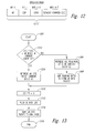
therefore be helpful. Figure 12 illustrates the four segments contained in the
CPCS-UU field according to one embodiment of the present invention. The
CPCS-UU field is one octet wide and includes an interrupt bit INT that
indicates the transmission of a current frame has been interrupted in order to
begin transmission of a higher priority frame. More specifically, when the INT
bit is set equal to 1 the ATM cell terminates the current DFU PDU being
transmitted and indicates the next ATM cell will contain the beginning of a
new DFU PDU. The second segment of the CPCS-UU field is an end of frame
bit EOF that indicates the current ATM cell terminates transmission of the
corresponding AAL5 PDU. When the EOF bit is set equal to 1, this indicates
all DFU PDUs making up a particular AAL5 PDU have been transmitted. The
third segment is an end of frame basic layer bit EOF0 that is set equal to 1 to
periodically synchronize the receiver 804 and transmitter 802 so that if an
ATM cell is lost the receiver may quickly recover and resume proper reception
of transmitted ATM cells, as will be described more detail below.
The final segment of the CPCS-UU field is a 4-bit segment count
SC contained in bits 4-7, as was previously mentioned with reference to Figure
10. The SC count is initially set equal to 0 and incremented each time a new
DFU PDU is transmitted to thereby count modulo 16 the number of DFU
PDUs transmitted. The SC count is utilized by the receiver 804 to ensure that
every DFU PDU comprising an AAL5 PDU is received, as will be described in
more detail below. Briefly, the receiver 804 maintains a corresponding next
segment count NS, which it increments each time a DFU PDU is received. In
this way, the receiver 804 determines whether the current DFU PDU just
received is the DFU PDU the receiver expects to receive next by comparing the
NS count maintained by the receiver to the SC count contained in the current
DFU PDU. When the two counts match, the receiver 804 determines the
current DFU PDU was properly received and that no intervening DFU PDUs
sent between the current DFU PDU and the prior DFU PDU were lost during
transmission. The SC count is necessary because the CRC segment in each
DFU PDU trailer provides error detection only for that DFU PDU, and there is
no CRC or other equivalent error detection at the frame level. Thus, if an
entire DFU PDU was to be lost during transmission, the receiver 804 would
have no way of detecting such a lost DFU PDU without the SC count. It
should be noted that the SC count does not allow the receiver 804 to determine
to which frame a lost DFU PDU belongs.
The operation of the payload generator 1002 in generating the
termination, full, and interrupt DFU PDU cells will now be discussed in more
detail with reference to Figures 13-15. Figure 13 is a flowchart illustrating the
process executed by the payload generator 1002 in generating a full DFU PDU
cell. The process begins in step 1300 the proceeds immediately step 1302
which determines whether the current queue QC contains less than 48 bytes of
the frame being transmitted. When the determination in step 1302 is negative,
the process proceeds to step 1304 and retrieves a 48 byte packet from the
current queue QC. When the determination in step 1302 is positive, the
process proceeds to step 1306 and retrieves all remaining bytes in the current
queue QC. It should be noted that when the determination in step 1302 is
positive, this indicates the current queue QC contains between 41 and 47 bytes
(see step 1112 in Figure 11). Once the process retrieves all remaining bytes
contained in the current queue QC in step 1306, the process proceeds to step
1308 and adds the required number of padding bytes to form a 48 byte packet.
This 48 byte packet forms the payload portion of a full ATM cell. From either
step 1304 or step 1308, the process proceeds to step 1310 and sets the PTI bit
equal to 0 indicating the ATM cell containing the 48 byte packet from either
step 1304 or 1308 is not the last ATM cell for the corresponding DFU PDU.
The process proceeds from step 1310 to step 1312 and pushes the current
queue number QC onto the LIFO register 1004. From step 1312, the process
proceeds to step 1314 and applies the 48 byte packet along with the PTI bit to
the ATM layer 818 and thereafter proceeds to step 1315 and terminates.
Figure 14 is a flowchart illustrating the process executed by the
payload generator 1002 in generating an interrupt DFU PDU cell. The process
begins in step 1400 and proceeds immediately step 1402 and retrieves 40 bytes
from the current queue QC. Recall, the payload generator 1002 generates an
interrupt DFU PDU cell when step 1116 (Figure 11) determines a queue QH
having a higher priority than the current queue QC contains a frame requiring
transmission. Once step 1402 retrieves 40 bytes from the current queue QC,
the process proceeds to step 1404 and sets the INT bit equal to 1. The INT bit
equal to 1 indicates the transmission of a current frame has been interrupted in
order to begin transmission of a higher priority frame (i.e., when the INT bit is
set equal to 1 the ATM cell terminates the current DFU PDU being
transmitted). From step 1404, the process proceeds to step 1406 and sets the
PTI bit equal to one, indicating the ATM cell is the last cell of the DFU PDU
currently being transmitted. The process then goes to step 1408 and sets the
SC count field equal to the FC count generated by the fragment counter 1006
which, as previously described, is incremented each time a new DFU PDU is
transmitted to thereby count modulo 16 the number of DFU PDUs transmitted.
After step 1408, the process proceeds to step 1410 and forms the 8 byte trailer
that includes the CPCS-UU field which, in turn, includes the INT and PTI bits
set equal to 1 and the SC count set equal to the FC count. From step 1410, the
process goes to step 1412 and pushes the current queue number QC onto the
LIFO register 1004. The process thereafter goes to step 1414 and pushes the
highest priority active queue number QH onto the LIFO register 1004. From
step 1414, the process goes to step 1416 and increments the FC count, and
thereafter goes to step 1418 and applies the 48 byte packet to the ATM layer
818. As previously discussed, the 48 byte packet includes the 40 bytes pulled
from the current queue QC along with the eight byte trailer T containing the
CPCS-UU field.
Figure 15 is a flowchart illustrating the process executed by the
payload generator 1002 in generating a termination DFU PDU cell. Recall, a
termination DFU PDU cell is generated when the current queue QC contains
40 bytes or less (see step 1112 in Figure 11). The process begins in step 1500
and proceeds immediately to step 1502 which retrieves all remaining bytes in
the current queue QC. From step 1502, the process proceeds to step 1504 and
adds any padding bytes required to round the bytes retrieves from the queue
QC to 40 bytes. For example, if the current queue QC contains 32 bytes, step
1504 will add 8 bytes to these 32 bytes so that the sum equals 40 bytes. The
process then goes to step 1506 and sets the PTI bit equal to 1, indicating the
ATM cell is the last cell of a corresponding DFU PDU. From step 1506, the
process proceeds to step 1507 and sets the EOF bit to 1, which instructs the
receiver 804 that the corresponding DFU PDU cell terminates the DFU PDU
currently being transmitted.
The process then goes to step 1508 and determines whether the
LIFO register 1004 is empty, which occurs when no packet queues Q1-QN
contains a frame or portion of a frame awaiting transmission. When the
determination in step 1508 is positive, the process goes to step 1510 and sets
the EOF0 bit to 1 so that the transmitter 802 and receiver 804 are synchronized
upon receipt of the corresponding termination DFU PDU cell, as will be
described more detail below. The process synchronizes the transmitter 802
and receiver 804 at this point since the LIFO register 1004 is empty, indicating
no frames are awaiting transmission. The process then proceeds to step 1512
and resets the FC count to 0. From step 1512, the process goes to step 1514
and forms the 48 byte packet including the CPCS-UU field having its bits set
according to the previous steps. The process sends the 48 byte packet to the
ATM layer 818 and then goes to step 1516 and terminates. When the
determination in step 1508 is negative, the process proceeds to step 1518 and
sets the EOF0 bit to 0 since the LIFO register 1004 is not empty. From step
1518, the process goes to step 1520 and pushes the queue number QH into the
LIFO register 1004. The process goes from step 1520 to step 1514 and sends
the corresponding 48 byte packet to the ATM layer 818, and thereafter goes to
step 1516 and ends.
Figure 16 is a state diagram illustrating the process executed by
the
state machine 824 of Figure 8 during operation of the
receiver 804. The
process starts and immediately enters an
initialization state 1600 during which
the
state machine 824 initializes a number of parameters. For example, during
the
initialization state 1600 the DRP level and NS count are set to 0. Once the
state machine 824 has initialized all required components in the
receiver 804,
the
initialization state 1600 terminates in the
state machine 824 begins
operation in a
synchronization state 1602. In the
synchronization state 1602,
the
state machine 824 waits for receipt of a synchronization ATM cell, which
is defined as an ATM cell containing the trailer of a corresponding DFU PDU
where the EOF,
EOF 0, and INT bits contained in the CPCS-UU field of the
trailer along with the PTI bit contained in the header H of ATM cell have a
predetermined values to define either an escape command ESC or a
synchronization command SYNC, as set forth below in Table 1.
| Command | INT | EOF | EOF0 | PTI |
| SYNC |
| | 0 | 1 | 1 | 1 |
| ESC | 1 | 1 | 1 | 1 |
The SYNC and ESC commands allow the transmitter 802 and
receiver 804 to be synchronized. It should be noted that only the SYNC
command is required when the receiver 804 is communicating with a
transmitter such as the transmitter 802 that communicates using the multiple
priority AAL5 protocol. The ESC command allows the receiver 804 to
communicate with a transmitter that communicates using the conventional
AAL5 protocol. In the conventional AAL5 protocol, the CPCS-UU field is
reserved and all of the bits in the CPCS-UU field are set to 1 whenever a trailer
is transmitted. Thus, an ESC command is received by the receiver 804
whenever the trailer of a conventional AAL5 PDU is transmitted using the
conventional AAL5 protocol.
The process operates in the synchronization state 1602 until a
synchronization ATM cell is received. When the synchronization ATM cell
contains the SYNC command, the process exits the synchronization state 1602
and goes to a step 1604 in which a dynamic reception priority level DRP and
the NS count are reset to 0 to thereby synchronize the receiver 804 and
transmitter 802, as previously mentioned with reference to Figure 8. Thus, the
next received DFU PDU is assigned DRP level 0 and must contain an SC count
set equal to 0. Once step 1604 has reset the DRP level and NS count, the
process commences operation in a receive state 1606. The receive state 1606
contains two sub modes of operation, a multiple priority sub mode and
conventional sub mode. When the receive state 1606 is entered from step
1604, the process executes in the receive state in the multiple priority sub
mode. In the multiple priority sub mode, the state machine 824 determines
whether each received DFU PDU is valid. As previously discussed, the state
machine 824 determines whether a received DFU PDU is valid by comparing
the SC count contained in the corresponding CPCS-UU field to the NS count
generated by the state machine 824 (Figure 8). When the two counts are equal,
the received DFU PDU is valid, and is otherwise invalid. In addition, the
AAL5 defragmentation module 822 (Figure 8) also performs error detection on
the received DFU PDU, such as through the CRC field of the DFU PDU, and
flags the state machine 824 when an error is detected. Thus, during operation
in the receive state 1606 a received DFU PDU is valid unless the SC count
does not equal the NS count or the module 822 detects an error in the received
DFU PDU. When the received DFU PDU is valid, the DFU PDU is processed
in step 1608 as previously described with reference to Figure 8. When an
invalid DFU PDU is detected, the state machine 824 terminates operation in
the receive state 1606 and returns to the synchronization state 1602 and awaits
receipt of either an ESC or SYNC command.
When the synchronization ATM cell contains the ESC command,
the process exits the synchronization state 1602 and goes directly to the receive
state 1606. When the receive state 1606 is entered in this way, the state
machine 824 operates in the conventional sub mode. In the conventional sub
mode, the state machine 824 ignores the CPCS-UU field and operates in
combination with the payload routing module 826 to route the payloads of
conventional AAL5 PDUs to the desired packet queue Q1-QN in a
predetermined manner.
The overall operation of the communications system 800 of
Figure 8 will now be described in more detail with reference to Figures 17 and
18. Figure 17 is a logical representation of the communications system 800 of
Figure 8 showing a plurality of AAL5 PDUs or frames A-G having the
associated priority levels PL1-PL3 as indicated, where the priority level PL1 is
the highest priority level, followed by level PL2, and then level PL3. In this
example, the transmission of the frame A begins, and frame B arrives for
transmission before the transmission of frame A is complete. The frame C
arrives for transmission before the transmission of the frame B is complete.
The frame D arrives for transmission after the transmission of frames B and C
has been completed, but before the transmission of frame A is complete. The
frame E also arrives before the transmission of frame A is complete, and the
frame F arrives for transmission during the transmission of frame E. The frame
G arrives for transmission after the frame F but during the transmission of
frame E. In this example, the receiver 804 receives the complete frame C first,
followed by the frames B, D, A, F, E, and G in that order as indicated in Figure
17 and as will now be described in more detail below.
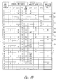
Figure 18 is a table illustrating the operation of the receiver 804
in receiving the frames A-G having the priority levels and being applied to the
transmitter 802 as just described with reference to Figure 17. The table shows
the status of the various bits in the CPCS-UU field of transmitted DFU PDUs
and the corresponding DRP level of each received DFU PDU. The left column
represents ATM cells, each cell being assigned a corresponding number from
1-25. The next five columns to the right illustrate information contained in
each of the ATM cells 1-25. More specifically, these columns illustrate the
status of the bits INT, EOF, EOF0, PTI, and SC. The next three columns to
the right illustrate the DRP level of each DFU PDU being received, with the
three levels DRP0-DRP2 being illustrated in the example of Figure 18. In the
three priority level columns DRP0-DRP2, an alphanumeric designation is
given to the portion or fragment of a DFU PDU contained in the corresponding
ATM cell. For example, the ATM cell numbers 3 and 4 carry the fragments
B1 and B2 of a corresponding DFU PDU formed by the two fragments. One
or more fragments make up a DFU PDU and one or more DFU PDUs, in turn,
make up a frame, as previously described. The far-right column illustrates the
reception order of each frame being transmitted using the multiple priority
AAL5 protocol. The X's in the table indicate a "don't care" condition for the
corresponding bit or field.
In the example of Figure 17, the ATM cell number 1 contains the
SYNC command which, as previously described, causes the receiver 804 to
reset the NS count and dynamic reception priority level to DRP0. The next
ATM cell number 2 begins the transmission of frame A. In the ATM cell
number 2, the INT and PTI bits are set. The set PTI bit indicates the ATM cell
number 2 is the last cell of the DFU PDU currently being processed, and the
set INT bit indicates the transmission of the frame A is being interrupted. In
response to the set INT bit, the receiver 804 increments the DRP level so that
the next DFU PDU being processed has the dynamic reception priority level
DRP1. In this example, the A1 fragment defines the first DFU PDU that is
processed for the frame A. The ATM cell numbers 3 and 4 are thereafter
processed and contain respective fragments B1 and B2 of the next DFU PDU
being processed. Note that the ATM cell number 3 does not contain a trailer
and thus contains no values for the INT, EOF, and EOF0 bits. Also, in ATM
cell number 3 the PTI bit is 0 indicating the ATM cell is not the last cell in the
current DFU PDU.
In the ATM cell number 4 the INT bit is set, indicating the
transmission of the current DFU PDU is being interrupted and causing the
receiver 804 to increment the DRP level to DRP2. The set PTI bit in ATM cell
number 4 indicates the cell is the last cell of DFU PDU currently being
processed. The ATM cell numbers 5-7 contain respective fragments C1-C3
that collectively form a DFU PDU corresponding to the frame C. Recall, the
frame C has the highest priority level PL1 in the transmitter 802. In the current
example, no other frames have higher priority levels than frame C and thus no
other frames can interrupt the transmission of frame C. As a result, frame C is
received in its entirety by the receiver 804 upon successive reception of the
ATM cell numbers 5-7. In the ATM cell number 7, the PTI bit is set indicating
this ATM cell is the last cell in the current DFU PDU. In addition, in the ATM
cell number 7 the EOF bit is set indicating the cell contains the end of the
current DFU PDU. In response to the set EOF bit, the receiver 804 decrements
the dynamic reception priority level so that the subsequent DFU PDU has the
dynamic reception priority level DRP1. In receiving the remaining frames, the
receiver 804 operates in a manner analogous to that just described for the
frames C and B, and thus, for the sake of brevity, this operation will not be
described in further detail.
The example illustrated in Figures 17 and 18 illustrates the
dynamic nature of the dynamic reception priority levels associated with the
frames A-G being communicated by the communications system 800. For
example, note that both frames C and F are assigned the highest priority level
PL1 in the transmitter 802. In the receiver 804, however, these frames are
assigned different dynamic reception priority levels, with the frame C being
assigned priority level DRP2 and the frame F being assigned the priority level
DRP1. The dynamic reception priority level assigned to a particular frame
depends on the priority levels of other frames being received in the receiver
804 when this particular frame is transmitted to the receiver. When the
receiver 804 starts receiving the frame C, the frame B having dynamic
reception priority level DRP1 was being received just prior. As a result, the
receiver 804 assigns the frame C the next highest dynamic reception priority
level DRP2. In contrast, when the receiver 804 starts receiving the frame F,
the frame E having the priority level DRP0 was being received just prior. As a
result, the frame F is assigned the next highest dynamic reception priority level
DRP1 in the receiver 804. This example illustrates how two different frames,
frames C and F, having the same priority level PL1 assigned by the transmitter
802 are assigned different dynamic reception priority levels in the receiver 804,
with the particular dynamic reception level assigned being determined
dynamically as a function of the frames currently being received by receiver.
It is to be understood that even though various embodiments and
advantages of the present invention have been set forth in the foregoing
description, the above disclosure is illustrative only, and changes may be made
in detail, and yet remain within the broad principles of the invention.
Therefore, the present invention is to be limited only by the appended claims.