EP1209773A1 - Attachment portion structure of connector - Google Patents
Attachment portion structure of connector Download PDFInfo
- Publication number
- EP1209773A1 EP1209773A1 EP01127956A EP01127956A EP1209773A1 EP 1209773 A1 EP1209773 A1 EP 1209773A1 EP 01127956 A EP01127956 A EP 01127956A EP 01127956 A EP01127956 A EP 01127956A EP 1209773 A1 EP1209773 A1 EP 1209773A1
- Authority
- EP
- European Patent Office
- Prior art keywords
- connector
- connector block
- wires
- block
- attachment portion
- Prior art date
- Legal status (The legal status is an assumption and is not a legal conclusion. Google has not performed a legal analysis and makes no representation as to the accuracy of the status listed.)
- Withdrawn
Links
- 238000006073 displacement reaction Methods 0.000 claims abstract description 7
- 239000000470 constituent Substances 0.000 description 2
Images


Classifications
-
- H—ELECTRICITY
- H01—ELECTRIC ELEMENTS
- H01R—ELECTRICALLY-CONDUCTIVE CONNECTIONS; STRUCTURAL ASSOCIATIONS OF A PLURALITY OF MUTUALLY-INSULATED ELECTRICAL CONNECTING ELEMENTS; COUPLING DEVICES; CURRENT COLLECTORS
- H01R13/00—Details of coupling devices of the kinds covered by groups H01R12/70 or H01R24/00 - H01R33/00
- H01R13/73—Means for mounting coupling parts to apparatus or structures, e.g. to a wall
- H01R13/74—Means for mounting coupling parts in openings of a panel
-
- H—ELECTRICITY
- H01—ELECTRIC ELEMENTS
- H01R—ELECTRICALLY-CONDUCTIVE CONNECTIONS; STRUCTURAL ASSOCIATIONS OF A PLURALITY OF MUTUALLY-INSULATED ELECTRICAL CONNECTING ELEMENTS; COUPLING DEVICES; CURRENT COLLECTORS
- H01R2201/00—Connectors or connections adapted for particular applications
- H01R2201/26—Connectors or connections adapted for particular applications for vehicles
Definitions
- the present invention relates to an attachment portion structure of a connector, in which a connector block having a plurality of terminals arranged therein is supported by a holder fixed to a stationary member in such a way as to be able to cause relative displacement with respect to the stationary member.
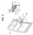
- an electronic module unit 100 shown in FIG. 3 has a structure adapted so that this module unit is fitted to a central recess portion of an instrumental panel from the front thereof.
- a panel side integrated connector 70 is provided on an attachment plate 81 placed in the front of an instrumental panel side, while a module side connector 101 to be connected to a panel side integrated connector 70 is fixed onto a lower part of an attachment surface 100b at the side of the rear surface of the electronic module unit 100.
- the module side connector 101 is connected to a panel side integrated connector 70, so that each of electronic devices is electrically connected to an instrumental panel side circuit.
- This connector 70 has an oblong connector block 71, in which a plurality of terminals are arranged, as illustrated in FIG. 3. A group 73 of wires respectively connected to the terminals 70 is rearwardly led out of this connector block 71. Further, this connector 70 has a housing portion 72a for accommodating the connector block 71. This housing portion 72a is supported by a holder 72 fixed to an attachment plate 81 in such a way as to be able to cause relative displacement with respect to the stationary attachment plate 81.
- a wire harness 73a which includes wires for a power supply system, for a signal system, for a camera image, and for controlling a heater, and antenna wires 73b for a television set, for a radio set, and for GPS, and a wire harness 73c for retrofitted optional equipment are collectively connected to the panel side integrated connector 70.
- the invention has been made to solve the problems with the related art, and therefore n object of the invention is to provide an attachment portion structure of a connector, which is enabled to hold a connector block in normal connection position and attitude, thereby to smoothly and reliably per form the connection between connectors.
- an attachment portion structure of a connector having a connector block, in which a plurality of terminals are arranged in a predetermined direction, supported by a holder fixed to a stationary member in such a way as to be able to cause relative displacement with respect to the stationary member.
- a group of wires connected to the connector is nearly equally divided into divided groups, which are respectively led out to opposite directions, at a rear portion of the connector block, and that each of the divided groups of wires is fixed to the stationary member.
- a group of wires connected to the connector is nearly equally divided into divided groups, which are respectively led out to opposite directions, at a rear portion of the connector block, and that each of the divided groups of wires is fixed to the stationary member. Forces caused by drawing the groups of wires therearound are uniformly exerted in the opposite directions on the connector block supported on the holder, and thus cancel out.
- the connector block is held in the normal connection position and attitude without tilting the connector block. Consequently, the connection of the connectors can be smoothly reliably connected to each other.
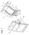
- FIGS. 1, 2A, and 2B illustrate the configuration of an example of an attachment portion structure of a connector according to the invention.
- An electronic module unit 100 has a structure adapted so that this module unit is fitted to a central recess portion of an instrumental panel from the front thereof.
- a panel side integrated connector 20 is provided on an attachment member 31 placed in the front of an instrumental panel side, while a module side connector 101 to be connected to a panel side integrated connector 70 is fixed onto a lower part of an attachment surface 100b at the side of the rear surface of the electronic module unit 100.
- a pair of left-hand side and right-hand side supports 32 and 33 obliquely and downwardly extend from a wire fixing member 34 extending in the direction of width thereof. Both bottom portions of the supports 32 and 33 are connected by a horizontal attachment member 31 to each other . Further, the connector 20 is connected to this attachment member 31.
- the connector 20 comprises a connector block 21, in which a plurality of terminals are arranged in a predetermined direction, and a holder 22 for supporting this connector block 21 and for fixing this block 21 to the stationary attachment member 31.
- the holder 22 has a housing portion 22a for accommodating portion 22a. Lock arms 22b for tentatively locking the connector block 21 are provided in this housing portion 22a. Further, the connector block 21 is locked by the lock arms 22b of the holder 22, so that the connector block 21 is supported thereon in such a way as to be able to cause relative displacement with respect to the stationary attachment member 31.
- a group of wires 40 is almost equally divided into divided groups, which are respectively led out to opposite sides.
- Each of the divided groups 41 and 42 of wires is fixed in such a manner as to extend along a corresponding one of a V-shaped right-hand side support 32 and a V-shaped left-hand side support 33, and led to a wire fixing member 34 laterally extending in a front panel portion.
- the divided groups 41 and 42 of wires are led to a predetermined connection portion together with other wires 43 provided around a front panel. Then, such wires are connected to one another thereat.
- the connector block 21 is attached to the housing portion 22a so that the connection between the connector block 21 and the counter-connector 101 slides in a connection direction from a connection standby position shown in FIG. 2A to a connection position shown in FIG. 2B.
- these constituent elements constitute a connecting force amplifying mechanism for amplifying the connecting force acting between both the connectors 20 and 101 when an operation of connecting the counter-connector 101 to the connector 20 is performed.
- connection structure of the connector which has this connecting force amplifying mechanism, is well known.
- the invention can be applied to a connector disclosed in, for example, JP-A-10-21992.
- the mechanism for supporting the connector block in such a way as to be able to cause relative displacement with respect to a stationary member is well known.
- the invention can be applied to the connector disclosed in, for instance, JP-A-10-134900.
- connection mechanism of a connector according to the invention is employed in the connector having such a connection amplifying mechanism
- the connector block is held in the normal connection standby position and attitude. This prevents an extra load other than the connection load from being applied to the connector when an operation of connecting the connector to the counter-connector is performed. Consequently, the connectors can be smoothly connected to each other by reliably increasing the connecting force between both the connectors in response to a sliding operation of the connector block.
- the attachment portion structure of the connector according to the invention is not limited to the aforementioned concrete configuration of the embodiment. Needless to say, the attachment portion structure of the connector may be suitably changed by modifying, adding or deleting constituent elements if necessary.
- the group of wires of the connector is nearly equally divided at a rear portion of the connector block into divided groups that are then led out to opposite sides, respectively.
- Each of the divided groups of wires is fixed to the corresponding stationary member. Forces caused by drawing the divided groups of wires therearound are uniformly exerted in the opposite directions on the connector block supported on the holder, and thus cancel out.
- the connector block is held in the normal connection position and attitude without tilting the connector block. Consequently, the connection of the connectors can be smoothly and reliably connected to each other.
Landscapes
- Details Of Connecting Devices For Male And Female Coupling (AREA)
- Connector Housings Or Holding Contact Members (AREA)
- Instrument Panels (AREA)
- Installation Of Indoor Wiring (AREA)
Abstract
An attachment structure of a connector is configured so
that a group 40 of wires connected to a connector 20, in which
a connector block 21 is supported by a holder 22 fixed to a
stationary attachment member 31 in such a way as to be able
to cause relative displacement with respect to a stationary
attachment member 31, is nearly equally divided into divided
groups at a rear portion of the connector block 21, and that
each of the divided groups of wires 41 and 42 is fixed to a
corresponding one of supports 32 and 33 for a stationary
attachment member 31.
Description
The present invention relates to an attachment portion
structure of a connector, in which a connector block having
a plurality of terminals arranged therein is supported by a
holder fixed to a stationary member in such a way as to be
able to cause relative displacement with respect to the
stationary member.
In recent years, there has been developed an apparatus
in which a plurality of electronic devices to be installed
on an instrumental panel of a vehicle as standard are modulated
as an electronic module unit.
For example, an electronic module unit 100 shown in FIG.
3 has a structure adapted so that this module unit is fitted
to a central recess portion of an instrumental panel from the
front thereof. A panel side integrated connector 70 is
provided on an attachment plate 81 placed in the front of an
instrumental panel side, while a module side connector 101
to be connected to a panel side integrated connector 70 is
fixed onto a lower part of an attachment surface 100b at the
side of the rear surface of the electronic module unit 100.
When this electronic module unit 100 is attached by being
fitted into a central recess portion of the instrumental panel
from the front thereof, the module side connector 101 is
connected to a panel side integrated connector 70, so that
each of electronic devices is electrically connected to an
instrumental panel side circuit.
This connector 70 has an oblong connector block 71, in
which a plurality of terminals are arranged, as illustrated
in FIG. 3. A group 73 of wires respectively connected to the
terminals 70 is rearwardly led out of this connector block
71. Further, this connector 70 has a housing portion 72a for
accommodating the connector block 71. This housing portion
72a is supported by a holder 72 fixed to an attachment plate
81 in such a way as to be able to cause relative displacement
with respect to the stationary attachment plate 81.
Incidentally, as shown in, for example, FIG. 4, a wire
harness 73a, which includes wires for a power supply system,
for a signal system, for a camera image, and for controlling
a heater, and antenna wires 73b for a television set, for a
radio set, and for GPS, and a wire harness 73c for retrofitted
optional equipment are collectively connected to the panel
side integrated connector 70.
In case of the conventional connection structure of a
connector, all the wires 73 to be connected to the connector
70 are bundled and led out in a single direction. Thus, a
force biased in a direction, in which the wires are led out,
is acted on the connector block 71, so that the connector block
71 is put into a tilted state. Consequently, the connector
block 71 cannot be held in normal connection standby position
and attitude. This may impede the connection between both
the connectors 70 and 101.
The invention has been made to solve the problems with
the related art, and therefore n object of the invention is
to provide an attachment portion structure of a connector,
which is enabled to hold a connector block in normal connection
position and attitude, thereby to smoothly and reliably per form
the connection between connectors.
According to the invention, there is provided an
attachment portion structure of a connector having a connector
block, in which a plurality of terminals are arranged in a
predetermined direction, supported by a holder fixed to a
stationary member in such a way as to be able to cause relative
displacement with respect to the stationary member. A group
of wires connected to the connector is nearly equally divided
into divided groups, which are respectively led out to opposite
directions, at a rear portion of the connector block, and that
each of the divided groups of wires is fixed to the stationary
member.
With the aforementioned configuration, a group of wires
connected to the connector is nearly equally divided into
divided groups, which are respectively led out to opposite
directions, at a rear portion of the connector block, and that
each of the divided groups of wires is fixed to the stationary
member. Forces caused by drawing the groups of wires
therearound are uniformly exerted in the opposite directions
on the connector block supported on the holder, and thus cancel
out. Thus, the connector block is held in the normal connection
position and attitude without tilting the connector block.
Consequently, the connection of the connectors can be smoothly
reliably connected to each other.
Hereinafter, an embodiment of the invention is concretely
described with reference to the accompanying drawings.
FIGS. 1, 2A, and 2B illustrate the configuration of an
example of an attachment portion structure of a connector
according to the invention.
An electronic module unit 100 has a structure adapted
so that this module unit is fitted to a central recess portion
of an instrumental panel from the front thereof. A panel side
integrated connector 20 is provided on an attachment member
31 placed in the front of an instrumental panel side, while
a module side connector 101 to be connected to a panel side
integrated connector 70 is fixed onto a lower part of an
attachment surface 100b at the side of the rear surface of
the electronic module unit 100.
Meanwhile, at the side of a vehicle body, a pair of
left-hand side and right-hand side supports 32 and 33 obliquely
and downwardly extend from a wire fixing member 34 extending
in the direction of width thereof. Both bottom portions of
the supports 32 and 33 are connected by a horizontal attachment
member 31 to each other . Further, the connector 20 is connected
to this attachment member 31.
The connector 20 comprises a connector block 21, in which
a plurality of terminals are arranged in a predetermined
direction, and a holder 22 for supporting this connector block
21 and for fixing this block 21 to the stationary attachment
member 31. The holder 22 has a housing portion 22a for
accommodating portion 22a. Lock arms 22b for tentatively
locking the connector block 21 are provided in this housing
portion 22a. Further, the connector block 21 is locked by
the lock arms 22b of the holder 22, so that the connector block
21 is supported thereon in such a way as to be able to cause
relative displacement with respect to the stationary
attachment member 31.
In an attachment portion structure 10 of this connector
20, a group of wires 40 is almost equally divided into divided
groups, which are respectively led out to opposite sides. Each
of the divided groups 41 and 42 of wires is fixed in such a
manner as to extend along a corresponding one of a V-shaped
right-hand side support 32 and a V-shaped left-hand side
support 33, and led to a wire fixing member 34 laterally
extending in a front panel portion. Furthermore, the divided
groups 41 and 42 of wires are led to a predetermined connection
portion together with other wires 43 provided around a front
panel. Then, such wires are connected to one another thereat.
According to this attachment portion structure 10, forces
caused by drawing the groups 41 and 42 of wires therearound
are uniformly exerted in the opposite directions on the
connector block 21 supported on the holder 22, and thus cancel
out. Consequently, the connector block 21 is held in normal
connection position and attitude without tilting the connector
block 21.
This prevents an extra load, which is other than a
connection load, from being imposed on when an operation of
connecting a counter-connector 101 to the connector 20 is
performed. Thus, when the electronic module unit 100 is fitted
from the front thereof into the central recess portion of the
instrumental panel thereby to be attached thereto, the module
side connector 101 is reliably connected to the panel side
integrated connector 20. Thus, each of electronic devices
is electrically connected to an instrumental panel side
circuit.
More particularly, the connector block 21 is attached
to the housing portion 22a so that the connection between the
connector block 21 and the counter-connector 101 slides in
a connection direction from a connection standby position shown
in FIG. 2A to a connection position shown in FIG. 2B. Thus,
these constituent elements constitute a connecting force
amplifying mechanism for amplifying the connecting force
acting between both the connectors 20 and 101 when an operation
of connecting the counter-connector 101 to the connector 20
is performed.
Incidentally, the connection structure of the connector,
which has this connecting force amplifying mechanism, is well
known. The invention can be applied to a connector disclosed
in, for example, JP-A-10-21992. Further, the mechanism for
supporting the connector block in such a way as to be able
to cause relative displacement with respect to a stationary
member is well known. The invention can be applied to the
connector disclosed in, for instance, JP-A-10-134900.
In the case that the connection mechanism of a connector
according to the invention is employed in the connector having
such a connection amplifying mechanism, the connector block
is held in the normal connection standby position and attitude.
This prevents an extra load other than the connection load
from being applied to the connector when an operation of
connecting the connector to the counter-connector is performed.
Consequently, the connectors can be smoothly connected to each
other by reliably increasing the connecting force between both
the connectors in response to a sliding operation of the
connector block.
In spite of the foregoing description, the attachment
portion structure of the connector according to the invention
is not limited to the aforementioned concrete configuration
of the embodiment. Needless to say, the attachment portion
structure of the connector may be suitably changed by modifying,
adding or deleting constituent elements if necessary.
As described above, in accordance with the attachment
portion structure according to the invention, the group of
wires of the connector is nearly equally divided at a rear
portion of the connector block into divided groups that are
then led out to opposite sides, respectively. Each of the
divided groups of wires is fixed to the corresponding
stationary member. Forces caused by drawing the divided
groups of wires therearound are uniformly exerted in the
opposite directions on the connector block supported on the
holder, and thus cancel out. Thus, the connector block is
held in the normal connection position and attitude without
tilting the connector block. Consequently, the connection
of the connectors can be smoothly and reliably connected to
each other.
Claims (1)
- An attachment portion structure of a connector having a connector block, in which has a plurality of terminals are arranged in a predetermined direction, supported by a holder fixed to a stationary member in such a way as to be able to cause relative displacement with respect to said stationary member;
wherein a group of wires connected to said connector is nearly equally divided into divided groups, which are respectively led out to opposite directions, at a rear portion of said connector block, and wherein each of said divided groups of wires is fixed to said stationary member.
Applications Claiming Priority (2)
| Application Number | Priority Date | Filing Date | Title |
|---|---|---|---|
| JP2000357216A JP2002154351A (en) | 2000-11-24 | 2000-11-24 | Connector mounting structure |
| JP2000357216 | 2000-11-24 |
Publications (1)
| Publication Number | Publication Date |
|---|---|
| EP1209773A1 true EP1209773A1 (en) | 2002-05-29 |
Family
ID=18829318
Family Applications (1)
| Application Number | Title | Priority Date | Filing Date |
|---|---|---|---|
| EP01127956A Withdrawn EP1209773A1 (en) | 2000-11-24 | 2001-11-23 | Attachment portion structure of connector |
Country Status (3)
| Country | Link |
|---|---|
| US (1) | US6659787B2 (en) |
| EP (1) | EP1209773A1 (en) |
| JP (1) | JP2002154351A (en) |
Families Citing this family (3)
| Publication number | Priority date | Publication date | Assignee | Title |
|---|---|---|---|---|
| US6830469B1 (en) * | 2004-03-19 | 2004-12-14 | Molex Incorporated | Electrical connector assembly |
| TWI548548B (en) | 2014-01-16 | 2016-09-11 | 提愛思科技股份有限公司 | Mounting member and seat equipped with airbag module |
| JP6815141B2 (en) * | 2016-09-13 | 2021-01-20 | イリソ電子工業株式会社 | Imaging device and harness side connector |
Citations (4)
| Publication number | Priority date | Publication date | Assignee | Title |
|---|---|---|---|---|
| US5184960A (en) * | 1992-04-06 | 1993-02-09 | Hopkins Manufacturing Corporation | Trailer light connection system |
| EP0863576A1 (en) * | 1997-03-05 | 1998-09-09 | Ryosei Electro-Circuit Systems Ltd. | Connector |
| US5902149A (en) * | 1996-12-10 | 1999-05-11 | Yazaki Corporation | Movable connector |
| US5941731A (en) * | 1996-06-03 | 1999-08-24 | Yazaki Corporation | Connector holding structure |
Family Cites Families (3)
| Publication number | Priority date | Publication date | Assignee | Title |
|---|---|---|---|---|
| JP3283378B2 (en) * | 1994-06-06 | 2002-05-20 | カルソニックカンセイ株式会社 | Vehicle connector arrangement structure |
| US5857863A (en) * | 1995-11-28 | 1999-01-12 | Harness System Techologies Research, Ltd. | Automobile instrument panel harness-connecting construction |
| JPH11297407A (en) * | 1998-04-09 | 1999-10-29 | Yazaki Corp | connector |
-
2000
- 2000-11-24 JP JP2000357216A patent/JP2002154351A/en not_active Withdrawn
-
2001
- 2001-11-15 US US09/987,728 patent/US6659787B2/en not_active Expired - Fee Related
- 2001-11-23 EP EP01127956A patent/EP1209773A1/en not_active Withdrawn
Patent Citations (4)
| Publication number | Priority date | Publication date | Assignee | Title |
|---|---|---|---|---|
| US5184960A (en) * | 1992-04-06 | 1993-02-09 | Hopkins Manufacturing Corporation | Trailer light connection system |
| US5941731A (en) * | 1996-06-03 | 1999-08-24 | Yazaki Corporation | Connector holding structure |
| US5902149A (en) * | 1996-12-10 | 1999-05-11 | Yazaki Corporation | Movable connector |
| EP0863576A1 (en) * | 1997-03-05 | 1998-09-09 | Ryosei Electro-Circuit Systems Ltd. | Connector |
Also Published As
| Publication number | Publication date |
|---|---|
| US6659787B2 (en) | 2003-12-09 |
| US20020064755A1 (en) | 2002-05-30 |
| JP2002154351A (en) | 2002-05-28 |
Similar Documents
| Publication | Publication Date | Title |
|---|---|---|
| US6811330B1 (en) | Structure for mounting cameras on a vehicle | |
| US7858905B2 (en) | Vehicular mirror with heater circuit module | |
| US7351116B2 (en) | Connecting element | |
| KR100298812B1 (en) | Modular Circuit Board Placement System | |
| JP2502183B2 (en) | Basic circuit card assembly | |
| US20060139519A1 (en) | Liquid crystal display | |
| US20010016432A1 (en) | Vehicle center cluster assembling structure with electrical connection | |
| US5205753A (en) | Circuit board structure | |
| CN118176632A (en) | Communication connector device | |
| US6659787B2 (en) | Attachment portion structure of connector | |
| JP7023741B2 (en) | Imaging device | |
| US20090061657A1 (en) | Holder for a flexible circuit board | |
| CN104202942A (en) | Printer | |
| US5986458A (en) | Test head for semiconductor tester | |
| US6801632B2 (en) | Microphone assembly for vehicular installation | |
| US9065218B2 (en) | Making contact in a force-optimized manner between electrical loads and printed circuit boards | |
| KR20180051950A (en) | Elctronic control device | |
| CN214335223U (en) | Vehicle-mounted sensor device and vehicle | |
| US6769922B1 (en) | Auxillary connectors for connectors of liquid crystal display device | |
| US6676156B2 (en) | Electronic impact sensor mounted on supporting member | |
| US5882219A (en) | Movable connector having an extending support plate | |
| EP1143571B1 (en) | Movable structure for connectors | |
| US20020050396A1 (en) | Power supply cable having a simple structure and an image reading apparatus using such a power supply cable | |
| JP2000198396A (en) | Wire harness arrangement structure for vehicle provided with cab tilt mechanism | |
| JP3535654B2 (en) | Connector and its mounting structure |
Legal Events
| Date | Code | Title | Description |
|---|---|---|---|
| PUAI | Public reference made under article 153(3) epc to a published international application that has entered the european phase |
Free format text: ORIGINAL CODE: 0009012 |
|
| AK | Designated contracting states |
Kind code of ref document: A1 Designated state(s): AT BE CH CY DE DK ES FI FR GB GR IE IT LI LU MC NL PT SE TR |
|
| AX | Request for extension of the european patent |
Free format text: AL;LT;LV;MK;RO;SI |
|
| AKX | Designation fees paid | ||
| REG | Reference to a national code |
Ref country code: DE Ref legal event code: 8566 |
|
| STAA | Information on the status of an ep patent application or granted ep patent |
Free format text: STATUS: THE APPLICATION IS DEEMED TO BE WITHDRAWN |
|
| 18D | Application deemed to be withdrawn |
Effective date: 20021130 |