EP1209539A2 - Air bearing mechanism for flattening paper in a printing machine - Google Patents
Air bearing mechanism for flattening paper in a printing machine Download PDFInfo
- Publication number
- EP1209539A2 EP1209539A2 EP01128069A EP01128069A EP1209539A2 EP 1209539 A2 EP1209539 A2 EP 1209539A2 EP 01128069 A EP01128069 A EP 01128069A EP 01128069 A EP01128069 A EP 01128069A EP 1209539 A2 EP1209539 A2 EP 1209539A2
- Authority
- EP
- European Patent Office
- Prior art keywords
- exterior wall
- transport element
- housing
- printing machine
- plenum
- Prior art date
- Legal status (The legal status is an assumption and is not a legal conclusion. Google has not performed a legal analysis and makes no representation as to the accuracy of the status listed.)
- Granted
Links
Images

Classifications
-
- G—PHYSICS
- G03—PHOTOGRAPHY; CINEMATOGRAPHY; ANALOGOUS TECHNIQUES USING WAVES OTHER THAN OPTICAL WAVES; ELECTROGRAPHY; HOLOGRAPHY
- G03G—ELECTROGRAPHY; ELECTROPHOTOGRAPHY; MAGNETOGRAPHY
- G03G15/00—Apparatus for electrographic processes using a charge pattern
- G03G15/65—Apparatus which relate to the handling of copy material
- G03G15/6555—Handling of sheet copy material taking place in a specific part of the copy material feeding path
- G03G15/6558—Feeding path after the copy sheet preparation and up to the transfer point, e.g. registering; Deskewing; Correct timing of sheet feeding to the transfer point
-
- B—PERFORMING OPERATIONS; TRANSPORTING
- B65—CONVEYING; PACKING; STORING; HANDLING THIN OR FILAMENTARY MATERIAL
- B65H—HANDLING THIN OR FILAMENTARY MATERIAL, e.g. SHEETS, WEBS, CABLES
- B65H5/00—Feeding articles separated from piles; Feeding articles to machines
- B65H5/22—Feeding articles separated from piles; Feeding articles to machines by air-blast or suction device
- B65H5/228—Feeding articles separated from piles; Feeding articles to machines by air-blast or suction device by air-blast devices
-
- G—PHYSICS
- G03—PHOTOGRAPHY; CINEMATOGRAPHY; ANALOGOUS TECHNIQUES USING WAVES OTHER THAN OPTICAL WAVES; ELECTROGRAPHY; HOLOGRAPHY
- G03G—ELECTROGRAPHY; ELECTROPHOTOGRAPHY; MAGNETOGRAPHY
- G03G15/00—Apparatus for electrographic processes using a charge pattern
- G03G15/14—Apparatus for electrographic processes using a charge pattern for transferring a pattern to a second base
- G03G15/16—Apparatus for electrographic processes using a charge pattern for transferring a pattern to a second base of a toner pattern, e.g. a powder pattern, e.g. magnetic transfer
- G03G15/163—Apparatus for electrographic processes using a charge pattern for transferring a pattern to a second base of a toner pattern, e.g. a powder pattern, e.g. magnetic transfer using the force produced by an electrostatic transfer field formed between the second base and the electrographic recording member, e.g. transfer through an air gap
- G03G15/1635—Apparatus for electrographic processes using a charge pattern for transferring a pattern to a second base of a toner pattern, e.g. a powder pattern, e.g. magnetic transfer using the force produced by an electrostatic transfer field formed between the second base and the electrographic recording member, e.g. transfer through an air gap the field being produced by laying down an electrostatic charge behind the base or the recording member, e.g. by a corona device
-
- B—PERFORMING OPERATIONS; TRANSPORTING
- B65—CONVEYING; PACKING; STORING; HANDLING THIN OR FILAMENTARY MATERIAL
- B65H—HANDLING THIN OR FILAMENTARY MATERIAL, e.g. SHEETS, WEBS, CABLES
- B65H2301/00—Handling processes for sheets or webs
- B65H2301/40—Type of handling process
- B65H2301/44—Moving, forwarding, guiding material
- B65H2301/443—Moving, forwarding, guiding material by acting on surface of handled material
- B65H2301/4432—Moving, forwarding, guiding material by acting on surface of handled material by means having an operating surface contacting only one face of the material, e.g. roller
- B65H2301/44322—Moving, forwarding, guiding material by acting on surface of handled material by means having an operating surface contacting only one face of the material, e.g. roller belt
-
- B—PERFORMING OPERATIONS; TRANSPORTING
- B65—CONVEYING; PACKING; STORING; HANDLING THIN OR FILAMENTARY MATERIAL
- B65H—HANDLING THIN OR FILAMENTARY MATERIAL, e.g. SHEETS, WEBS, CABLES
- B65H2301/00—Handling processes for sheets or webs
- B65H2301/40—Type of handling process
- B65H2301/44—Moving, forwarding, guiding material
- B65H2301/446—Assisting moving, forwarding or guiding of material
- B65H2301/4461—Assisting moving, forwarding or guiding of material by blowing air towards handled material
-
- B—PERFORMING OPERATIONS; TRANSPORTING
- B65—CONVEYING; PACKING; STORING; HANDLING THIN OR FILAMENTARY MATERIAL
- B65H—HANDLING THIN OR FILAMENTARY MATERIAL, e.g. SHEETS, WEBS, CABLES
- B65H2406/00—Means using fluid
- B65H2406/10—Means using fluid made only for exhausting gaseous medium
- B65H2406/11—Means using fluid made only for exhausting gaseous medium producing fluidised bed
- B65H2406/113—Details of the part distributing the air cushion
- B65H2406/1132—Multiple nozzles arrangement
-
- G—PHYSICS
- G03—PHOTOGRAPHY; CINEMATOGRAPHY; ANALOGOUS TECHNIQUES USING WAVES OTHER THAN OPTICAL WAVES; ELECTROGRAPHY; HOLOGRAPHY
- G03G—ELECTROGRAPHY; ELECTROPHOTOGRAPHY; MAGNETOGRAPHY
- G03G15/00—Apparatus for electrographic processes using a charge pattern
- G03G15/14—Apparatus for electrographic processes using a charge pattern for transferring a pattern to a second base
- G03G15/16—Apparatus for electrographic processes using a charge pattern for transferring a pattern to a second base of a toner pattern, e.g. a powder pattern, e.g. magnetic transfer
- G03G15/1665—Apparatus for electrographic processes using a charge pattern for transferring a pattern to a second base of a toner pattern, e.g. a powder pattern, e.g. magnetic transfer by introducing the second base in the nip formed by the recording member and at least one transfer member, e.g. in combination with bias or heat
Definitions
- the invention relates generally to a color or monochrome reprographic printing system, and more particularly concerns apparatus for delivering the paper or other media to a photoconductive surface, offset printing roll, etc.
- a photoconductive member (often a photoreceptor belt) is charged to a substantially uniform potential to sensitize the surface thereof. The charged portion of the photoconductive member is thereafter selectively exposed. Exposure of the charged photoconductive member dissipates the charge thereon in the irradiated areas. This records an electrostatic latent image on the photoconductive member corresponding to the informational areas contained within the original document being reproduced. After the electrostatic latent image is recorded on the photoconductive member, the latent image is treated with toner particles and is subsequently transferred to a copy sheet. The copy sheet is heated to permanently affix the toner image thereto in image configuration.
- Multi-color electrophotographic printing is substantially identical to the foregoing process of black and white printing. However, rather than forming a single latent image on the photoconductive surface, successive latent images corresponding to different colors are recorded thereon. Each single color electrostatic latent image is developed with toner of a color complementary thereto. This process is repeated in a plurality of cycles for differently colored images and their respective complementarily colored toner. Each single color toner image is transferred to the copy sheet in superimposed registration with the prior toner image. Alternately, a plurality of images may be superimposed on the photoreceptor surface, and transferred simultaneously to the sheet. This creates a multi-layered toner image on the copy sheet. Thereafter, the multi-layered toner image is permanently affixed to the copy sheet creating a color copy.
- the developer material may be a liquid or a powder material.
- Surface irregularities in the paper may be occur as the paper (copy media) travels through the machine. Such irregularities may be caused by the various rollers and belts which carry the paper through the printing or other machine processes. For example, irregularities could occur as side one is fused before transferring an image to side two, or because of the characteristics of the paper stock due to manufacturing, humidity, etc. In addition, misalignment, excessive force, etc. may create localized deformities in the copy paper. As a result, air gaps may form between the paper and the photoreceptor belt. Such gaps result in poor transfer of toner from the belt to the paper, which may, in turn, cause deletions or distortions in the printed copy.
- the disclosure of this patent is incorporated herein by reference.
- the roller described in the '268 is a pneumatic roller having an internal chamber which is selectively connected to a source of fluid under pressure or a vacuum. Through holes in the exterior periphery of the roller, copy paper, which is being handled by the roller, may be selectively subjected to pressure or vacuum. This is said to improve the paper handling performance of the transport system. It is a purpose of this invention to adapt the pneumatic roller concept to enhance the delivery of copy paper to an image transfer station.
- a bearing surface of constant shape is constructed to provide a cushion of air between the print medium and the moving supporting surface.
- the air cushion causes a downward pressure to hold the medium to the transport element, i.e. a belt or drum, as the media is moved towards the image transfer station or other process station of the printing machine.
- the air bearing surface is positioned just upstream from the image transfer station to minimize distortion of the media as it is transferred to the electrostatic belt or drum.
- a housing is constructed just upstream of the image transfer station, adjacent the transport element.
- the housing contains a plenum for storing air under pressure.
- the housing has an exterior wall, the outer surface of which faces the path of the copy paper to form a bearing surface.
- the bearing surface is constructed to conform to the shape of the transport element. For example, a belt would generally require a flat bearing surface and a drum may require a slightly arcuate bearing surface.
- the plenum is connected to a source of pressurized air through a series of valves. Sensors within the plenum monitor the pressure in the plenum and control the supply of air through the valves.
- An array of holes are constructed in the exterior wall to allow streams of pressurized air to escape to lubricate and form the bearing surface. The streams of pressurized air form a cushion outside the exterior wall to separate the copy paper from the wall and generate an overall pressure against the paper to encourage its flat engagement with the transport element. A flat, well aligned, presentation of the copy paper to the image transfer station may then be accomplished without supplementary transport elements which rely on physical contact.
- an electrostatic transfer element is mounted on the housing adjacent to said path to generate a charge on said print media to assist transfer of toner from belt to print media.
- the source of air is a fan mounted on the housing.
- the holes are canted so that the air escapes with a component of force in the direction of said path.
- the holes are arranged to generate components of force in opposing orientations to tenter said sheets.
- the housing is mounted on the printing machine by means of a resilient mounting element.
- the resilient mounting element is a series of springs.
- the machine further comprises:
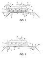
- an air bearing transport element 1 is depicted as part of a paper transport system of a copy machine. This portion of the transport system could be just upstream of an image transfer station at which paper alignment and flatness is critical. The air bearing transport element 1 could also be useful immediately prior to the heating station at which the paper is heated by the fuser roll. This invention could also be used in printers and other paper handling environments. Although it will be described in the context of handling copy paper in a copier, it would be equally advantageous in the handling of other copy or print media.
- the transport element 1 is positioned adjacent to the path of copy paper 2 at a point where copy paper 2 is being transported into or through image transfer station 3 on transport belt 4.
- air bearing 1 is positioned partially over support roller 5 to engage the paper prior to contact with the belt 4.
- belt 4 is a photoreceptor element and contains the toner image 30.
- Transport belt 4 is mounted for movement on driven rollers or pulleys 5 and 6, as shown by arrows 7 and 8.
- Transport element 1 is constructed of a housing 9 in which a plenum 10 is defined by side walls 11 and 12 and exterior wall 13.
- An air diffuser 14 acts as a cover to seal the plenum and a bracket to support fan 16 which is driven by motor 15.
- the housing is resiliently supported by the frame of the copy machine 17 through springs 18 and 19 or other resilient elements which are capable of reducing vibration and allowing alignment of the housing 9 with transport belt 2.
- Pressurized air may be supplied by a fan 15, as shown, or other suitable blower or compressor.
- the source of pressurized air charges plenum 10 during operation of the copy machine.
- An array of openings 20 are constructed in the exterior wall 13 of the housing 9 to allow air to escape from plenum 10 and coat the exterior surface 21 to form a bearing surface 22.
- Bearing surface 22 spreads between the paper 2 and the exterior surface 21 of housing 9 to force the paper 2 towards belt 4. This action tends to flatten the paper 2, as it makes initial contact to the photoreceptor or transfer roll of an offset press, as shown in figure 1. Such action will also tend to hold it more firmly to the support surface of belt 4 as it moves towards the image transfer station 3.
- the image formed by the toner on the photoreceptor belt is generally shielded from infiltrating air currents originating at the air bearing surface 22 by means of a skimmer.
- paper 2 will block air from blowing directly on the toner image. An air current of significant velocity is thereby avoided that might dislodge the toner which is electrostatically bonded to the photoreceptor.
- Exterior surface 21 may be shaped to conform to the opposing surface of transport element 4. This would be advantageous in the case of the transport element 4 being a drum instead of the belt as shown.
- An appropriate control system for the air supply may include a release valve 24 and a sensor 25 to prevent the accumulation of excessive pressure.
- the pressurized air supply could be located remote from the housing 9 and communicate through a flexible hose. Air flow would be controlled by a valve which would be opened and closed by signals from the main copier process controller or by feeding back to a voltage controllable pressure source.
- a device i.e. corotron 23, for electrostatically charging the copy medium to assist in the transfer of toner is mounted in housing 9.
- At least a portion of the array of holes 20 are canted forward at an angle x of about 45° to the direction of paper travel. This generates components of force which tenter or stretch the sheet, thereby, tending to further flatten any buckles. Upstream of the position where the sheet 2 contacts the photoreceptor, the canted holes 20 assist sheet transport without the need to use driver rollers.
- FIG 4. Another alternate embodiment is shown in figure 4.
- a double surface of air is generated by positioning a second air bearing plenum 26 under plenum 10 and transporting the paper between the two bearing surfaces.
- a fan 28 or other source of pressurized air supplies air to plenum 26.
- Holes 27 in plenum 26 allow air to escape and form a support surface for sheet 2.
- the dual air bearing surface is positioned before sheet 2 makes contact with the photoreceptor. This configuration provides enhanced flattening of sheet 2 while fully supporting sheet 2 without physical contact. This is particularly useful when a previously toned image exists on the top side of sheet 2.
Landscapes
- Physics & Mathematics (AREA)
- General Physics & Mathematics (AREA)
- Engineering & Computer Science (AREA)
- Mechanical Engineering (AREA)
- Delivering By Means Of Belts And Rollers (AREA)
- Supply, Installation And Extraction Of Printed Sheets Or Plates (AREA)
- Electrostatic Charge, Transfer And Separation In Electrography (AREA)
Abstract
Description
In one embodiment of the printing machine defined in
Claims (10)
- A device for supplementing the transport of sheets of print media on a transport element of a printing machine in a predetermined path comprising:a first housing having side walls and an exterior wall which cooperate to define a first interior plenum, said first housing mounted adjacent to said transport element in said media path with said exterior wall facing said transport element;a first source of pressurized air communicating with said first plenum to supply said plenum with pressurized air; anda first array of holes constructed in said exterior wall of said first plenum to allow said pressurized air to escape therefrom to form a first air cushion at said exterior wall between said exterior wall and the print media, said first air cushion urging said print media into flat engagement with the transport element.
- A device for supplementing the transport of sheets of print media on a transport element of a printing machine in a predetermined path, as described in claim 1, wherein said device is an electrographic printer.
- A device for supplementing the transport of sheets of print media on a transport element of a printing machine in a predetermined path, as described in claim 1, wherein said device is a sheet fed offset press.
- An electrophotographic printing machine in which a print medium is transported to an image transfer station by a transport element, comprising:an image transfer station mounted in the machine in the path of said print medium to which the image is to be transferred;a transport element constructed in advance of said image transfer station to deliver said print medium to said image transfer station in a predetermined path and direction;a first housing having side walls and an exterior wall which cooperate to define a first interior plenum, said first housing mounted adjacent to said transport element in said paper path with said exterior wall facing said transport element;a first source of pressurized air communicating with said first plenum to supply said first plenum with pressurized air; andan array of holes constructed in said exterior wall of said first plenum to allow pressurized air to escape therefrom to form a first air cushion at said exterior wall between said exterior wall and the print medium, said air cushion urging said print medium into flat engagement with said transport element.
- An electrophotographic printing machine in which a print medium is transported to an image transfer station by a transport element, as described in claim 4, wherein an electrostatic tacking element is mounted on the housing adjacent to said paper path to generate a charge on said paper which tends to attract said paper to said transport element.
- An electrophotographic printing machine in which a print medium is transported to an image transfer station by a transport element, as described in claim 4, wherein the source of air is a fan mounted on the housing.
- An electrophotographic printing machine in which a print medium is transported to an image transfer station by a transport element, as described in claim 4, wherein the holes are canted so that the air escapes with a component of force in the direction of said paper path.
- An electrophotographic printing machine in which a print medium is transported to an image transfer station by a transport element, as described in claim 4, wherein said housing is mounted on the printing machine by means of a resilient mounting element.
- An electrophotographic printing machine in which a print medium is transported to an image transfer station by a transport element, as described in claim 8, wherein said resilient mounting element is a series of springs.
- A device for supplementing the transport of sheets of print media on a transport element of a printing machine in a predetermined path, as described in claim 1, further comprising:a second housing having side walls and an exterior wall which cooperate to define an interior plenum, said second housing mounted opposite to said first housing with said exterior wall of said second housing facing said exterior wall of said first housing and wherein said path of said print medium passes in between;a second source of pressurized air communicating with said second plenum to supply said second plenum with pressurized air; anda second array of holes constructed in said exterior wall of said second housing to allow pressurized air to escape therefrom to form a second air cushion at said exterior wall of said second housing between said exterior wall and the print medium, said first and second air cushions supporting said print medium there between.
Applications Claiming Priority (2)
| Application Number | Priority Date | Filing Date | Title |
|---|---|---|---|
| US721679 | 1996-09-27 | ||
| US09/721,679 US6442369B1 (en) | 2000-11-27 | 2000-11-27 | Air bearing mechanism for flattening paper in a printing machine |
Publications (3)
| Publication Number | Publication Date |
|---|---|
| EP1209539A2 true EP1209539A2 (en) | 2002-05-29 |
| EP1209539A3 EP1209539A3 (en) | 2006-02-08 |
| EP1209539B1 EP1209539B1 (en) | 2008-08-06 |
Family
ID=24898873
Family Applications (1)
| Application Number | Title | Priority Date | Filing Date |
|---|---|---|---|
| EP01128069A Expired - Lifetime EP1209539B1 (en) | 2000-11-27 | 2001-11-26 | Air bearing mechanism for flattening paper in a printing machine |
Country Status (4)
| Country | Link |
|---|---|
| US (1) | US6442369B1 (en) |
| EP (1) | EP1209539B1 (en) |
| JP (1) | JP3934918B2 (en) |
| DE (1) | DE60135197D1 (en) |
Cited By (4)
| Publication number | Priority date | Publication date | Assignee | Title |
|---|---|---|---|---|
| EP1411010A3 (en) * | 2002-10-18 | 2004-06-09 | Kabushiki Kaisha Toshiba | Paper sheet detection apparatus |
| EP1475326A1 (en) * | 2003-05-08 | 2004-11-10 | MASCHINENBAU OPPENWEILER BINDER GmbH & Co. KG | Air blast hold down apparatus and sheet alignment apparatus provided therewith |
| US9010925B2 (en) | 2013-07-15 | 2015-04-21 | Xerox Corporation | Air film support device for an inkjet printer |
| WO2019177623A1 (en) | 2018-03-16 | 2019-09-19 | Hewlett-Packard Development Company, L.P. | Air bearings |
Families Citing this family (5)
| Publication number | Priority date | Publication date | Assignee | Title |
|---|---|---|---|---|
| US7077019B2 (en) * | 2003-08-08 | 2006-07-18 | Photon Dynamics, Inc. | High precision gas bearing split-axis stage for transport and constraint of large flat flexible media during processing |
| US7918124B2 (en) * | 2007-11-05 | 2011-04-05 | Machine Concepts, Inc. | Non-contact shape sensor and device for moving sheet material |
| DE102012019051B4 (en) * | 2011-10-17 | 2022-08-11 | Heidelberger Druckmaschinen Ag | Transport device for sheets with overhead blast air chamber |
| US9459086B2 (en) | 2014-02-17 | 2016-10-04 | Machine Concepts, Inc. | Shape sensor devices, shape error detection systems, and related shape sensing methods |
| US9670616B2 (en) | 2014-12-11 | 2017-06-06 | Georgia-Pacific Consumer Products Lp | Active web spreading and stabilization shower |
Family Cites Families (12)
| Publication number | Priority date | Publication date | Assignee | Title |
|---|---|---|---|---|
| US3382360A (en) * | 1965-09-10 | 1968-05-07 | Xerox Corp | Xerographic charging system having means for providing an air cushion between the charging device and the xerographic drum |
| GB1450450A (en) * | 1973-12-21 | 1976-09-22 | Xerox Corp | Electrostatography |
| JPS5388734A (en) * | 1977-01-14 | 1978-08-04 | Canon Inc | Transfer device |
| JPH0772811B2 (en) * | 1987-11-10 | 1995-08-02 | 株式会社日立製作所 | Double-sided recording device |
| DE4039311A1 (en) * | 1989-06-24 | 1992-06-11 | Heidelberger Druckmasch Ag | System for smoothing sheet against printing press cylinder - uses air nozzle with ends offset from middle part |
| US5467111A (en) * | 1991-06-06 | 1995-11-14 | Fuji Photo Film Co., Ltd. | Transporting apparatus for scanning exposure |
| US5235393A (en) * | 1992-01-06 | 1993-08-10 | Eastman Kodak Company | Toner image-fixing apparatus having air cooling device |
| US5379999A (en) * | 1993-07-23 | 1995-01-10 | Eastman Kodak Company | Sheet media handling apparatus |
| US5921544A (en) * | 1995-11-30 | 1999-07-13 | Xerox Corporation | Acquisition levitation transport device |
| US5913268A (en) | 1998-02-17 | 1999-06-22 | Xerox Corporation | Pneumatic rollers and paper handling arrangements |
| US6119052A (en) * | 1998-03-02 | 2000-09-12 | Xerox Corporation | Market-based control system for controlling object motion with smart matter |
| EP0960845A1 (en) * | 1998-05-28 | 1999-12-01 | Xerox Corporation | Pneumatic paper path |
-
2000
- 2000-11-27 US US09/721,679 patent/US6442369B1/en not_active Expired - Lifetime
-
2001
- 2001-11-13 JP JP2001346910A patent/JP3934918B2/en not_active Expired - Lifetime
- 2001-11-26 DE DE60135197T patent/DE60135197D1/en not_active Expired - Lifetime
- 2001-11-26 EP EP01128069A patent/EP1209539B1/en not_active Expired - Lifetime
Cited By (7)
| Publication number | Priority date | Publication date | Assignee | Title |
|---|---|---|---|---|
| EP1411010A3 (en) * | 2002-10-18 | 2004-06-09 | Kabushiki Kaisha Toshiba | Paper sheet detection apparatus |
| EP1475326A1 (en) * | 2003-05-08 | 2004-11-10 | MASCHINENBAU OPPENWEILER BINDER GmbH & Co. KG | Air blast hold down apparatus and sheet alignment apparatus provided therewith |
| US7281711B2 (en) | 2003-05-08 | 2007-10-16 | Maschinenbau Oppenweiler Binder Gmbh & Co. Kg | Blowing-air holding-down arrangement and sheet-aligning device provided therewith |
| US9010925B2 (en) | 2013-07-15 | 2015-04-21 | Xerox Corporation | Air film support device for an inkjet printer |
| WO2019177623A1 (en) | 2018-03-16 | 2019-09-19 | Hewlett-Packard Development Company, L.P. | Air bearings |
| EP3765906A4 (en) * | 2018-03-16 | 2021-09-01 | Hewlett-Packard Development Company, L.P. | Air bearings |
| US11294323B2 (en) | 2018-03-16 | 2022-04-05 | Hewlett-Packard Development Company, L.P. | Air bearings |
Also Published As
| Publication number | Publication date |
|---|---|
| JP2002167078A (en) | 2002-06-11 |
| EP1209539B1 (en) | 2008-08-06 |
| JP3934918B2 (en) | 2007-06-20 |
| EP1209539A3 (en) | 2006-02-08 |
| DE60135197D1 (en) | 2008-09-18 |
| US6442369B1 (en) | 2002-08-27 |
Similar Documents
| Publication | Publication Date | Title |
|---|---|---|
| US7962084B2 (en) | Fixing device and image forming apparatus | |
| US8688021B2 (en) | Glossing device, fixing device, and image forming apparatus incorporating same | |
| US20050147454A1 (en) | Air diffusing vacuum transport belt | |
| US6687468B2 (en) | Multi-position fuser nip cam | |
| US6442369B1 (en) | Air bearing mechanism for flattening paper in a printing machine | |
| JP5125151B2 (en) | Fixing device and image forming apparatus using the same | |
| US4169673A (en) | Image transfer device | |
| JP2005208574A (en) | Image forming method and image forming apparatus | |
| JP3428907B2 (en) | Image forming device | |
| US20070140751A1 (en) | Fusing member temperature uniformity enhancement system | |
| JP2000289878A (en) | Belt cleaning device for image forming apparatus | |
| EP1431840B1 (en) | Toner image transfer apparatus | |
| JP6221861B2 (en) | Conveying apparatus and image forming apparatus | |
| JPH06301296A (en) | Exfoliation of paper from photosensitive- body belt at low stress | |
| US7471923B2 (en) | Linear fusing nip zone | |
| JP4649204B2 (en) | Fixing device for image forming apparatus | |
| US6766131B1 (en) | Liquid electrophotographic developing apparatus using air pressure to hold liquid developer therewithin | |
| JPH08328395A (en) | Image forming device | |
| JP3118724B2 (en) | Image forming device | |
| JP3407584B2 (en) | Image forming device | |
| JP2000281232A (en) | Sheet material conveying device and image forming device | |
| JP3493953B2 (en) | Image forming device | |
| JP2002156869A (en) | Electrostatic photographic copying machine provided with mechanism for reduction coning belt | |
| JPH11338201A (en) | Double-sided printing device | |
| JP3518250B2 (en) | Transfer device in image forming apparatus |
Legal Events
| Date | Code | Title | Description |
|---|---|---|---|
| PUAI | Public reference made under article 153(3) epc to a published international application that has entered the european phase |
Free format text: ORIGINAL CODE: 0009012 |
|
| AK | Designated contracting states |
Kind code of ref document: A2 Designated state(s): AT BE CH CY DE DK ES FI FR GB GR IE IT LI LU MC NL PT SE TR |
|
| AX | Request for extension of the european patent |
Free format text: AL;LT;LV;MK;RO;SI |
|
| PUAL | Search report despatched |
Free format text: ORIGINAL CODE: 0009013 |
|
| AK | Designated contracting states |
Kind code of ref document: A3 Designated state(s): AT BE CH CY DE DK ES FI FR GB GR IE IT LI LU MC NL PT SE TR |
|
| AX | Request for extension of the european patent |
Extension state: AL LT LV MK RO SI |
|
| 17P | Request for examination filed |
Effective date: 20060808 |
|
| AKX | Designation fees paid |
Designated state(s): DE FR GB |
|
| 17Q | First examination report despatched |
Effective date: 20060925 |
|
| 17Q | First examination report despatched |
Effective date: 20060925 |
|
| GRAJ | Information related to disapproval of communication of intention to grant by the applicant or resumption of examination proceedings by the epo deleted |
Free format text: ORIGINAL CODE: EPIDOSDIGR1 |
|
| GRAP | Despatch of communication of intention to grant a patent |
Free format text: ORIGINAL CODE: EPIDOSNIGR1 |
|
| GRAP | Despatch of communication of intention to grant a patent |
Free format text: ORIGINAL CODE: EPIDOSNIGR1 |
|
| GRAS | Grant fee paid |
Free format text: ORIGINAL CODE: EPIDOSNIGR3 |
|
| GRAA | (expected) grant |
Free format text: ORIGINAL CODE: 0009210 |
|
| AK | Designated contracting states |
Kind code of ref document: B1 Designated state(s): DE FR GB |
|
| REG | Reference to a national code |
Ref country code: GB Ref legal event code: FG4D |
|
| REF | Corresponds to: |
Ref document number: 60135197 Country of ref document: DE Date of ref document: 20080918 Kind code of ref document: P |
|
| PLBE | No opposition filed within time limit |
Free format text: ORIGINAL CODE: 0009261 |
|
| STAA | Information on the status of an ep patent application or granted ep patent |
Free format text: STATUS: NO OPPOSITION FILED WITHIN TIME LIMIT |
|
| 26N | No opposition filed |
Effective date: 20090507 |
|
| REG | Reference to a national code |
Ref country code: FR Ref legal event code: PLFP Year of fee payment: 15 |
|
| REG | Reference to a national code |
Ref country code: FR Ref legal event code: PLFP Year of fee payment: 16 |
|
| REG | Reference to a national code |
Ref country code: FR Ref legal event code: PLFP Year of fee payment: 17 |
|
| REG | Reference to a national code |
Ref country code: FR Ref legal event code: PLFP Year of fee payment: 18 |
|
| PGFP | Annual fee paid to national office [announced via postgrant information from national office to epo] |
Ref country code: DE Payment date: 20191021 Year of fee payment: 19 |
|
| PGFP | Annual fee paid to national office [announced via postgrant information from national office to epo] |
Ref country code: FR Payment date: 20191022 Year of fee payment: 19 |
|
| PGFP | Annual fee paid to national office [announced via postgrant information from national office to epo] |
Ref country code: GB Payment date: 20191022 Year of fee payment: 19 |
|
| REG | Reference to a national code |
Ref country code: DE Ref legal event code: R119 Ref document number: 60135197 Country of ref document: DE |
|
| GBPC | Gb: european patent ceased through non-payment of renewal fee |
Effective date: 20201126 |
|
| PG25 | Lapsed in a contracting state [announced via postgrant information from national office to epo] |
Ref country code: FR Free format text: LAPSE BECAUSE OF NON-PAYMENT OF DUE FEES Effective date: 20201130 |
|
| PG25 | Lapsed in a contracting state [announced via postgrant information from national office to epo] |
Ref country code: GB Free format text: LAPSE BECAUSE OF NON-PAYMENT OF DUE FEES Effective date: 20201126 Ref country code: DE Free format text: LAPSE BECAUSE OF NON-PAYMENT OF DUE FEES Effective date: 20210601 |