EP1209518A2 - Foam core imaging element with improved optical performance - Google Patents
Foam core imaging element with improved optical performance Download PDFInfo
- Publication number
- EP1209518A2 EP1209518A2 EP01204392A EP01204392A EP1209518A2 EP 1209518 A2 EP1209518 A2 EP 1209518A2 EP 01204392 A EP01204392 A EP 01204392A EP 01204392 A EP01204392 A EP 01204392A EP 1209518 A2 EP1209518 A2 EP 1209518A2
- Authority
- EP
- European Patent Office
- Prior art keywords
- layer
- imaging
- paper
- imaging member
- foam core
- Prior art date
- Legal status (The legal status is an assumption and is not a legal conclusion. Google has not performed a legal analysis and makes no representation as to the accuracy of the status listed.)
- Withdrawn
Links
Classifications
-
- G—PHYSICS
- G03—PHOTOGRAPHY; CINEMATOGRAPHY; ANALOGOUS TECHNIQUES USING WAVES OTHER THAN OPTICAL WAVES; ELECTROGRAPHY; HOLOGRAPHY
- G03G—ELECTROGRAPHY; ELECTROPHOTOGRAPHY; MAGNETOGRAPHY
- G03G7/00—Selection of materials for use in image-receiving members, i.e. for reversal by physical contact; Manufacture thereof
- G03G7/006—Substrates for image-receiving members; Image-receiving members comprising only one layer
- G03G7/0073—Organic components thereof
- G03G7/008—Organic components thereof being macromolecular
-
- B—PERFORMING OPERATIONS; TRANSPORTING
- B32—LAYERED PRODUCTS
- B32B—LAYERED PRODUCTS, i.e. PRODUCTS BUILT-UP OF STRATA OF FLAT OR NON-FLAT, e.g. CELLULAR OR HONEYCOMB, FORM
- B32B5/00—Layered products characterised by the non- homogeneity or physical structure, i.e. comprising a fibrous, filamentary, particulate or foam layer; Layered products characterised by having a layer differing constitutionally or physically in different parts
- B32B5/18—Layered products characterised by the non- homogeneity or physical structure, i.e. comprising a fibrous, filamentary, particulate or foam layer; Layered products characterised by having a layer differing constitutionally or physically in different parts characterised by features of a layer of foamed material
-
- B—PERFORMING OPERATIONS; TRANSPORTING
- B41—PRINTING; LINING MACHINES; TYPEWRITERS; STAMPS
- B41M—PRINTING, DUPLICATING, MARKING, OR COPYING PROCESSES; COLOUR PRINTING
- B41M5/00—Duplicating or marking methods; Sheet materials for use therein
- B41M5/26—Thermography ; Marking by high energetic means, e.g. laser otherwise than by burning, and characterised by the material used
- B41M5/40—Thermography ; Marking by high energetic means, e.g. laser otherwise than by burning, and characterised by the material used characterised by the base backcoat, intermediate, or covering layers, e.g. for thermal transfer dye-donor or dye-receiver sheets; Heat, radiation filtering or absorbing means or layers; combined with other image registration layers or compositions; Special originals for reproduction by thermography
- B41M5/41—Base layers supports or substrates
-
- B—PERFORMING OPERATIONS; TRANSPORTING
- B41—PRINTING; LINING MACHINES; TYPEWRITERS; STAMPS
- B41M—PRINTING, DUPLICATING, MARKING, OR COPYING PROCESSES; COLOUR PRINTING
- B41M5/00—Duplicating or marking methods; Sheet materials for use therein
- B41M5/50—Recording sheets characterised by the coating used to improve ink, dye or pigment receptivity, e.g. for ink-jet or thermal dye transfer recording
- B41M5/502—Recording sheets characterised by the coating used to improve ink, dye or pigment receptivity, e.g. for ink-jet or thermal dye transfer recording characterised by structural details, e.g. multilayer materials
- B41M5/508—Supports
-
- G—PHYSICS
- G03—PHOTOGRAPHY; CINEMATOGRAPHY; ANALOGOUS TECHNIQUES USING WAVES OTHER THAN OPTICAL WAVES; ELECTROGRAPHY; HOLOGRAPHY
- G03C—PHOTOSENSITIVE MATERIALS FOR PHOTOGRAPHIC PURPOSES; PHOTOGRAPHIC PROCESSES, e.g. CINE, X-RAY, COLOUR, STEREO-PHOTOGRAPHIC PROCESSES; AUXILIARY PROCESSES IN PHOTOGRAPHY
- G03C1/00—Photosensitive materials
- G03C1/76—Photosensitive materials characterised by the base or auxiliary layers
- G03C1/795—Photosensitive materials characterised by the base or auxiliary layers the base being of macromolecular substances
-
- G—PHYSICS
- G03—PHOTOGRAPHY; CINEMATOGRAPHY; ANALOGOUS TECHNIQUES USING WAVES OTHER THAN OPTICAL WAVES; ELECTROGRAPHY; HOLOGRAPHY
- G03C—PHOTOSENSITIVE MATERIALS FOR PHOTOGRAPHIC PURPOSES; PHOTOGRAPHIC PROCESSES, e.g. CINE, X-RAY, COLOUR, STEREO-PHOTOGRAPHIC PROCESSES; AUXILIARY PROCESSES IN PHOTOGRAPHY
- G03C1/00—Photosensitive materials
- G03C1/76—Photosensitive materials characterised by the base or auxiliary layers
- G03C1/775—Photosensitive materials characterised by the base or auxiliary layers the base being of paper
- G03C1/79—Macromolecular coatings or impregnations therefor, e.g. varnishes
-
- G—PHYSICS
- G03—PHOTOGRAPHY; CINEMATOGRAPHY; ANALOGOUS TECHNIQUES USING WAVES OTHER THAN OPTICAL WAVES; ELECTROGRAPHY; HOLOGRAPHY
- G03C—PHOTOSENSITIVE MATERIALS FOR PHOTOGRAPHIC PURPOSES; PHOTOGRAPHIC PROCESSES, e.g. CINE, X-RAY, COLOUR, STEREO-PHOTOGRAPHIC PROCESSES; AUXILIARY PROCESSES IN PHOTOGRAPHY
- G03C1/00—Photosensitive materials
- G03C1/76—Photosensitive materials characterised by the base or auxiliary layers
- G03C1/81—Photosensitive materials characterised by the base or auxiliary layers characterised by anticoiling means
-
- Y—GENERAL TAGGING OF NEW TECHNOLOGICAL DEVELOPMENTS; GENERAL TAGGING OF CROSS-SECTIONAL TECHNOLOGIES SPANNING OVER SEVERAL SECTIONS OF THE IPC; TECHNICAL SUBJECTS COVERED BY FORMER USPC CROSS-REFERENCE ART COLLECTIONS [XRACs] AND DIGESTS
- Y10—TECHNICAL SUBJECTS COVERED BY FORMER USPC
- Y10S—TECHNICAL SUBJECTS COVERED BY FORMER USPC CROSS-REFERENCE ART COLLECTIONS [XRACs] AND DIGESTS
- Y10S430/00—Radiation imagery chemistry: process, composition, or product thereof
- Y10S430/134—Brightener containing
Definitions
- This invention relates to imaging media.
- it relates to supports for photographic, ink jet, thermal, and electrophotographic media.
- a print imaging support In order for a print imaging support to be widely accepted by the consumer for imaging applications, it has to meet requirements for preferred basis weight, caliper, stiffness, smoothness, gloss, whiteness, and opacity. Supports with properties outside the typical range for 'imaging media' suffer low consumer acceptance.
- imaging supports are also subject to other specific requirements depending upon the mode of image formation onto the support.
- the photographic paper it is important that the photographic paper be resistant to penetration by liquid processing chemicals failing which there is present a stain on the print border accompanied by a severe loss in image quality.
- the paper In the formation of 'photo-quality' ink jet paper, it is important that the paper is readily wetted by ink and that it exhibits the ability to absorb high concentrations of ink and dry quickly. If the ink is not absorbed quickly, the elements block (stick) together when stacked against subsequent prints and exhibit smudging and uneven print density.
- the support it is important that the support contain an insulative layer in order to maximize the transfer of dye from the donor which results in a higher color saturation.
- a conventional photographic paper comprises a cellulose paper base that has applied thereto a layer of polyolefin resin, typically polyethylene, on each side, which serves to provide waterproofing to the paper and also provides a smooth surface on which the photosensitive layers are formed.
- polyolefin resin typically polyethylene
- biaxially oriented polyolefin sheets are extrusion laminated to cellulose paper to create a support for silver halide imaging layers.
- the biaxially oriented sheets described therein have a microvoided layer in combination with coextruded layers that contain white pigments such as TiO 2 above and below the microvoided layer.
- the composite imaging support structure described has been found to be more durable, sharper, and brighter than prior art photographic paper imaging supports that use cast melt extruded polyethylene layers coated on cellulose paper.
- porous coatings comprising inorganic pigments and anionic, organic binders are blade coated to cellulose paper to create 'photo-quality' ink jet paper.
- imaging supports multiple operations are required to manufacture and assemble all of the individual layers.
- photographic paper typically requires a paper-making operation followed by a polyethylene extrusion coating operation, or as disclosed in U.S. patent 5,866,282, a paper-making operation is followed by a lamination operation for which the laminates are made in yet another extrusion casting operation.
- imaging supports that can be manufactured in a single in-line manufacturing process while still meeting the stringent features and quality requirements of imaging bases.
- Polymer foams have previously found significant application in food and drink containers, packaging, furniture, appliances, etc.
- Polymer foams have also been referred to as cellular polymers, foamed plastic, or expanded plastic.
- Polymer foams are multiple phase systems comprising a solid polymer matrix that is continuous and a gas phase. For example, U.S.
- Patent 4,832,775 discloses a composite foam/film structure which comprises a polystyrene foam substrate, oriented polypropylene film applied to at least one major surface of the polystyrene foam substrate, and an acrylic adhesive component securing the polypropylene film to said major surface of the polystyrene foam substrate.
- the foregoing composite foam/film structure can be shaped by conventional processes as thermoforming to provide numerous types of useful articles including cups, bowls, and plates, as well as cartons and containers that exhibit excellent levels of puncture, flex-crack, grease and abrasion resistance, moisture barrier properties, and resiliency.
- JP 2839905 B2 discloses a 3-layer structure comprising a foamed polyolefin layer on the image-receiving side, raw paper base, and a polyethylene resin coat on the backside.
- the foamed resin layer was created by extruding a mixture of 20 weight % titanium dioxide master batch in low density polyethylene, 78 weight % polypropylene, and 2 weight % of Daiblow PE-M20 (AL)NK blowing agent through a T-die. This foamed sheet was then laminated to the paper base using a hot melt adhesive.
- JP 09127648 A highlights a variation of the JP 2839905 B2 structure, in which the resin on the backside of the paper base is foamed, while the image receiving side resin layer is unfoamed.
- Another variation is a 4-layer structure highlighted in JP 09106038 A.
- the image receiving resin layer comprises of 2 layers, an unfoamed resin layer which is in contact with the emulsion, and a foamed resin layer which is adhered to the paper base.
- the thickness restriction is further needed to maintain the structural integrity of the photographic paper base since the raw paper base is providing the stiffness. It is known by those versed in the art of foaming that it is very difficult to make thin uniform foamed films with substantial reduction in density especially in the thickness range noted above.
- a further requirement for a reflective support is to provide a white or near white appearance, as well as an opaque platform for the imaging layer.
- a white background is necessary to provide the highlight areas of the image.
- An opaque layer is needed to maximize the scattering of the light and prevent show through.
- the layer immediately below the emulsion has a large impact on the image sharpness of the print due to the scattering of light during exposure of the print paper to the negative (To RC or Not to RC, Crawford, Gray and Parsons, Journal of Applied Photographic Engineering, 110-117 (1979)).
- Large amounts of TiO 2 in the 10 to 15 percent range or higher, are added to this layer to enhance image sharpness and, in turn, hiding power and opacity of the imaging support. Given the fact that ink jet, thermal, and most high end imaging media were derived from and are now in competition with photographic imaging media, the need for comparable degrees of opacity become necessary.
- an imaging member comprising an imaging layer and a base wherein said base comprises a closed cell foam core sheet and adhered thereto an upper and lower flange sheet, and wherein said imaging member has a stiffness of between 50 and 250 millinewtons and at least one layer of said base comprises whitening agent and said element has L* of greater than 90.4.
- This invention provides a superior imaging support. Specifically, it provides an imaging support of high stiffness, excellent smoothness, high opacity, whiteness, and excellent humidity curl resistance. It also provides an imaging support that can be manufactured using a single in-line operation. It also provides an imaging support that can be effectively recycled.
- the invention produces an element that has much less tendency to curl when exposed to extremes in humidity.
- the element can be manufactured in a single in-line operation. This significantly lowers element manufacturing costs and would eliminate disadvantages in the manufacturing of the current generation of imaging supports including very tight moisture specifications in the raw base and specifications to minimize pits during resin coating.
- the element can also be recycled to recover and reuse polyolefin instead of being discarded into landfills. It is an objective of this invention to use foam at the core of the imaging base, with high modulus flange layers that provide the needed stiffness surrounding the foam core on either side. Using this approach, many new features of the imaging base may be exploited, and restrictions in manufacturing eliminated.
- the imaging member of the invention comprises a polymer foam core that has adhered thereto an upper and a lower flange sheet.
- the polymer foam core comprises a homopolymer such as a polyolefin, polystyrene, polyvinylchloride or other typical thermoplastic polymers; their copolymers or their blends thereof; or other polymeric systems like polyurethanes, polyisocyanurates that has been expanded through the use of a blowing agent to consist of two phases, a solid polymer matrix, and a gaseous phase.
- Other solid phases may be present in the foams in the form of fillers that are of organic (polymeric, fibrous) or inorganic (glass, ceramic, metal) origin.
- the fillers may be used for physical, optical (lightness, whiteness, and opacity), chemical, or processing property enhancements of the foam.
- the foaming of these polymers may be carried out through several mechanical, chemical, or physical means.
- Mechanical methods include whipping a gas into a polymer melt, solution, or suspension, which then hardens either by catalytic action or heat or both, thus entrapping the gas bubbles in the matrix.
- Chemical methods include such techniques as the thermal decomposition of chemical blowing agents generating gases such as nitrogen or carbon dioxide by the application of heat or through exothermic heat of reaction during polymerization.
- Physical methods include such techniques as the expansion of a gas dissolved in a polymer mass upon reduction of system pressure; the volatilization of low-boiling liquids such as fluorocarbons or methylene chloride, or the incorporation of hollow microspheres in a polymer matrix.
- the choice of foaming technique is dictated by desired foam density reduction, desired properties, and manufacturing process.
- polyolefins such as polyethylene and polypropylene, their blends and their copolymers are used as the matrix polymer in the foam core along with a chemical blowing agent such as sodium bicarbonate and its mixture with citric acid, organic acid salts, azodicarbonamide, azobisformamide, azobisisobutyrolnitrile, diazoaminobenzene, 4,4'-oxybis(benzene sulfonyl hydrazide) (OBSH), N,N'-dinitrosopentamethyltetramine (DNPA), sodium borohydride, and other blowing agent agents well known in the art.
- a chemical blowing agent such as sodium bicarbonate and its mixture with citric acid, organic acid salts, azodicarbonamide, azobisformamide, azobisisobutyrolnitrile, diazoaminobenzene, 4,4'-oxybis(benzene sulfonyl hydrazide) (OBSH), N,N'
- the preferred chemical blowing agents would be sodium bicarbonate/citric acid mixtures, azodicarbonamide; though others can also be used. If necessary, these foaming agents may be used together with an auxiliary foaming agent, nucleating agent, and a cross-linking agent.
- the flange sheets of this invention are chosen to satisfy specific requirements of flexural modulus, caliper, surface roughness, and optical properties such as colorimetry and opacity.
- the flange members may be formed integral with the foam core by manufacturing the foam core with a flange skin sheet or the flange may be laminated to the foam core material.
- the integral extrusion of flange members with the core is preferred for cost.
- the lamination technique allows a wider range of properties and materials to be used for the skin materials. Imaging elements are constrained to a range in stiffness and caliper. At stiffness below a certain minimum stiffness, there is a problem with the element in print stackability and print conveyance during transport through photofinishing equipment, particularly high speed photoprocessors.
- Imaging elements are typically constrained by consumer performance and present processing machine restrictions to a stiffness range of between approximately 50 mN and 250 mN and a caliper range of between approximately 100 ⁇ m and 400 ⁇ m.
- stiffness of the imaging element can be altered by changing the caliper of the flange elements and/or changing the modulus of the flange elements and/or changing the modulus of the foam core.
- the target overall stiffness and caliper of the imaging element are specified then for a given core thickness and core material, the target caliper and modulus of the flange elements are implicitly constrained. Conversely, given a target stiffness and caliper of the imaging element for a given caliper and modulus of the flange sheets, the core thickness and core modulus are implicitly constrained.
- the preferred caliper of the foam core of the invention ranges between 200 ⁇ m and 350 ⁇ m
- the caliper of the flange sheets of the invention ranges between 10 ⁇ m and 175 ⁇ m
- the modulus of the foam core of the invention ranges between 30 MPa and 1000 MPa
- the modulus of the flange sheets of the invention ranges from 700 MPa to 10500 MPa.
- the above range is preferred because of (a) consumer preference, (b) manufacturability, and (c) materials selection. It is noted that the final choice of flange and core materials, modulus, and caliper will be a subject of the target overall element stiffness and caliper.
- the selection of flange materials and treatments (for example, the addition of strength agents, etc. for paper base or the use of filler materials for polymeric flange materials) determines the flange modulus.
- the flange sheet caliper is then constrained to 25 ⁇ m on each side of the core, and the flange modulus required is 10343 MPa, properties that can be met using a high modulus paper base.
- the flange sheet caliper is constrained to 50 ⁇ m on each side and the flange modulus required is 1034 MPa, properties that can be met using a polyolefin flange sheet.
- the flange sheets used comprise paper.
- the paper of this invention can be made on a standard continuous fourdrinier wire machine or on other modern paper formers. Any pulps known in the art to provide paper may be used in this invention. Bleached hardwood chemical kraft pulp is preferred, as it provides brightness, a good starting surface, and good formation while maintaining strength.
- Paper flange sheets useful to this invention are of caliper between about 25 ⁇ m and about 100 ⁇ m, preferably between about 30 ⁇ m and about 70 ⁇ m because then the overall element thickness is in the range preferred by customers for imaging element and processes in existing equipment. They must be "smooth" as to not interfere with the viewing of images.
- Chemical additives to impart hydrophobicity (sizing), wet strength, and dry strength may be used as needed.
- Inorganic filler materials such as TiO 2 , talc, and CaCO 3 clays may be used to enhance optical properties and reduce cost as needed.
- Dyes, biocides, processing chemicals, etc. may also be used as needed.
- the paper may also be subject to smoothing operations such as dry or wet calendering, as well as to coating through an in-line or an off-line paper coater.
- the flange sheets used comprise high modulus polymers such as high density polyethylene, polypropylene, or polystyrene; their blends or their copolymers; that have been stretched and oriented. They may be filled with suitable filler materials as to increase the modulus of the polymer and enhance other properties such as opacity and smoothness.
- suitable filler materials are talc, clays, calcium carbonate, magnesium carbonate, barium sulfate, mica, aluminum hydroxide (trihydrate), wollastonite, glass fibers and spheres, silica, various silicates, and carbon black.
- organic fillers used are wood flour, jute fibers, sisal fibers, polyester fibers, and the like.
- the preferred fillers are talc, mica, and calcium carbonate because they provide excellent modulus enhancing properties.
- Polymer flange sheets useful to this invention are of caliper between about 10 ⁇ m and about 150 ⁇ m, preferably between about 35 ⁇ m and about 70 ⁇ m.
- the elements of the invention can be made using several different manufacturing methods.
- the coextrusion, quenching, orienting, and heat setting of the element may be effected by any process which is known in the art for producing oriented sheet, such as by a flat sheet process or a bubble or tubular process.
- the flat sheet process involves extruding the blend through a slit die and rapidly quenching the extruded web upon a chilled casting drum so that the foam core component of the element and the polymeric integral flange components are quenched below their glass solidification temperature.
- the flange components may be extruded through a multiple stream die with the outer flange forming polymer streams not containing foaming agent, Alternatively, the surface of the foaming agent containing polymer may be cooled to prevent surface foaming and form a flange.
- the quenched sheet is then biaxially oriented by stretching in mutually perpendicular directions at a temperature above the glass transition temperature and below the melting temperature of the matrix polymers.
- the sheet may be stretched in one direction and then in a second direction or may be simultaneously stretched in both directions. After the sheet has been stretched, it is heat set by heating to a temperature sufficient to crystallize or anneal the polymers while restraining, to some degree, the sheet against retraction in both directions of stretching.
- the element while described as having preferably at least three layers of a foam core and a flange layer on each side, may also be provided with additional layers that may serve to change the properties of the element.
- Imaging elements could be formed with surface layers that would provide an improved adhesion or look.
- These elements may be coated or treated after the coextrusion and orienting process or between casting and full orientation with any number of coatings which may be used to improve the properties of the sheets including printability, to provide a vapor barrier, to make them heat sealable, or to improve the adhesion to the support or to the photosensitive layers.
- coatings which may be used to improve the properties of the sheets including printability, to provide a vapor barrier, to make them heat sealable, or to improve the adhesion to the support or to the photosensitive layers.
- acrylic coatings for printability coating polyvinylidene chloride for heat seal properties.
- Further examples include flame, plasma, or corona discharge treatment to improve printability or adhesion.
- the element may also be made through the extrusion laminating process.
- Extrusion laminating is carried out by bringing together the paper or polymeric flange sheets of the invention and the foam core with application of an adhesive between them, followed by their being pressed in a nip such as between two rollers.
- the adhesive may be applied to either the flange sheets or the foam core prior to their being brought into the nip.
- the adhesive is applied into the nip simultaneously with the flange sheets and the foam core.
- the adhesive may be any suitable material that does not have a harmful effect upon the element.
- a preferred material is polyethylene that is melted at the time it is placed into the nip between the foam core and the flange sheet.
- Addenda may also be added to the adhesive layer. Any know material used in the art to improve the optical performance of the system may be used. The use of TiO 2 is preferred. During the lamination process also, it is desirable to maintain control of the tension of the flange sheets in order to minimize curl in the resulting laminated receiver support.
- the suitable range in caliper of the foam core is from 25 ⁇ m to 350 ⁇ m.
- the preferred caliper range is between 50 ⁇ m and 200 ⁇ m because of the preferred overall caliper range of the element which lies between 100 ⁇ m and 400 ⁇ m.
- the range in density reduction of the foam core is from 20% to 95%.
- the preferred range in density reduction is between 40% and 70%. This is because it is difficult to manufacture a uniform product with very high density reduction (over 70%). Density reduction is the percent difference between solid polymer and a particular foam sample. It is also not economical to manufacture a product with density reduction less than 40%.
- the flange sheets used comprise paper on one side and a high modulus polymeric material on the other side.
- an integral skin may be on one side and another skin laminated to the other side of the foam core.
- the caliper of the paper and of the high modulus polymeric material is determined by the respective flexural modulus such that the overall stiffness of the imaging element lies within the preferred range, and the bending moment around the central axis is balanced to prevent excessive curl.
- an imaging element needs to meet constraints in surface smoothness and optical properties such as opacity and colorimetry.
- Surface smoothness characteristics may be met during flange-sheet manufacturing operations such as during paper making or during the manufacture of oriented polymers like oriented polystyrene. Alternatively, it may be met by extrusion coating additional layer(s) of polymers such as polyethylene onto the flange sheets in contact with a textured chill-roll or similar technique known by those skilled in the art.
- Optical properties such as opacity and colorimetry may be met by the appropriate use of filler materials such as titanium dioxide and calcium carbonate and colorants, dyes and/or optical brighteners or other additives known to those skilled in the art.
- the fillers may be in the flange or an overcoat layer, such as polyethylene.
- base materials for color print imaging materials are white, possibly with a blue tint as a slight blue is preferred to form a preferred white look to whites in an image.
- Any suitable white pigment may be incorporated in the polyolefin layer such as, for example, titanium dioxide, zinc oxide, zinc sulfide, zirconium dioxide, white lead, lead sulfate, lead chloride, lead aluminate, lead phthalate, antimony trioxide, white bismuth, tin oxide, white manganese, white tungsten, and combinations thereof.
- the pigment is used in any form that is conveniently dispersed within the flange or resin coat layers.
- the preferred pigment is titanium dioxide.
- suitable optical brightener may be employed in the polyolefin layer including those described in Research Disclosure, Vol. No. 308, December 1989, Publication 308119, Paragraph V, page 998.
- additives such as antioxidants, slip agents, or lubricants, and light stabilizers in the plastic elements as well as biocides in the paper elements.
- additives are added to improve, among other things, the dispersibility of fillers and/or colorants, as well as the thermal and color stability during processing and the manufacturability and the longevity of the finished article.
- the polyolefin coating may contain antioxidants such as 4,4'-butylidene-bis(6-tert-butyl-meta-cresol), di-lauryl-3,3'-thiopropionate, N-butylated-p-aminophenol, 2,6-di-tert-butyl-p-cresol, 2,2-di-tert-butyl-4-methyl-phenol, N,N-disalicylidene-1,2-diaminopropane, tetra(2,4-tert-butylphenyl)-4,4'-diphenyl diphosphonite, octadecyl 3-(3',5'-di-tert-butyl-4'-hydroxyphenyl propionate), combinations of the above, and the like; heat stabilizers, such as higher aliphatic acid metal salts such as magnesium stearate, calcium stearate, zinc stearate, aluminum stearate, calcium palmitate, zirs
- the phrase 'imaging element' comprises an imaging support as described above along with an image receiving layer as applicable to multiple techniques governing the transfer of an image onto the imaging element. Such techniques include thermal dye transfer, electrophotographic printing, or ink jet printing, as well as a support for photographic silver halide images.
- the phrase "photographic element” is a material that utilizes photosensitive silver halide in the formation of images.
- the thermal dye image-receiving layer of the receiving elements of the invention may comprise, for example, a polycarbonate, a polyurethane, a polyester, polyvinyl chloride, poly(styrene-co-acrylonitrile), poly(caprolactone), or mixtures thereof.
- the dye image-receiving layer may be present in any amount that is effective for the intended purpose. In general, good results have been obtained at a concentration of from about 1 to about 10 g/m 2 .
- An overcoat layer may be further coated over the dye-receiving layer, such as described in U.S. Patent No. 4,775,657 of Harrison et al.
- Dye-donor elements that are used with the dye-receiving element of the invention conventionally comprise a support having thereon a dye containing layer. Any dye can be used in the dye-donor employed in the invention, provided it is transferable to the dye-receiving layer by the action of heat. Especially good results have been obtained with sublimable dyes.
- Dye donors applicable for use in the present invention are described, e.g., in U.S. Patent Nos. 4,916,112; 4,927,803; and 5,023,228. As noted above, dye-donor elements are used to form a dye transfer image.
- Such a process comprises image-wise-heating a dye-donor element and transferring a dye image to a dye-receiving element as described above to form the dye transfer image.
- a dye donor element is employed which compromises a poly(ethylene terephthalate) support coated with sequential repeating areas of cyan, magenta, and yellow dye, and the dye transfer steps are sequentially performed for each color to obtain a three-color dye transfer image.
- the process is only performed for a single color, then a monochrome dye transfer image is obtained.
- Thermal printing heads which can be used to transfer dye from dye-donor elements to receiving elements of the invention are available commercially. There can be employed, for example, a Fujitsu Thermal Head (FTP-040 MCS001), a TDK Thermal Head F415 HH7-1089, or a Rohm Thermal Head KE 2008-F3. Alternatively, other known sources of energy for thermal dye transfer may be used, such as lasers as described in, for example, GB No. 2,083,726A.
- a thermal dye transfer assemblage of the invention comprises (a) a dye-donor element, and (b) a dye-receiving element as described above, the dye-receiving element being in a superposed relationship with the dye-donor element so that the dye layer of the donor element is in contact with the dye image-receiving layer of the receiving element.
- the above assemblage is formed on three occasions during the time when heat is applied by the thermal printing head. After the first dye is transferred, the elements are peeled apart. A second dye-donor element (or another area of the donor element with a different dye area) is then brought in register with the dye-receiving element and the process repeated. The third color is obtained in the same manner.
- the electrographic and electrophotographic processes and their individual steps have been well described in the prior art.
- the processes incorporate the basic steps of creating an electrostatic image, developing that image with charged, colored particles (toner), optionally transferring the resulting developed image to a secondary substrate, and fixing the image to the substrate.
- Toner charged, colored particles
- the first basic step, creation of an electrostatic image can be accomplished by a variety of methods.
- the electrophotographic process of copiers uses imagewise photodischarge, through analog or digital exposure, of a uniformly charged photoconductor.
- the photoconductor may be a single-use system, or it may be rechargeable and reimageable, like those based on selenium or organic photoreceptors.
- the electrophotographic process of copiers uses imagewise photodischarge, through analog or digital exposure, of a uniformly charged photoconductor.
- the photoconductor may be a single-use system, or it may be rechargeable and reimageable, like those based on selenium or organic photoreceptors.
- electrostatic images are created ionographically.
- the latent image is created on dielectric (charge-holding) medium, either paper or film. Voltage is applied to selected metal styli or writing nibs from an array of styli spaced across the width of the medium, causing a dielectric breakdown of the air between the selected styli and the medium. Ions are created, which form the latent image on the medium.
- Electrostatic images are developed with oppositely charged toner particles.
- the liquid developer is brought into direct contact with the electrostatic image.
- a flowing liquid is employed to ensure that sufficient toner particles are available for development.
- the field created by the electrostatic image causes the charged particles, suspended in a nonconductive liquid, to move by electrophoresis.
- the charge of the latent electrostatic image is thus neutralized by the oppositely charged particles.
- the toned image is transferred to paper (or other substrate).
- the paper is charged electrostatically, with the polarity chosen to cause the toner particles to transfer to the paper.
- the toned image is fixed to the paper.
- residual liquid is removed from the paper by air-drying or heating. Upon evaporation of the solvent, these toners form a film bonded to the paper.
- thermoplastic polymers are used as part of the particle. Heating both removes residual liquid and fixes the toner to paper.
- the recording elements or media When used as ink jet imaging media, the recording elements or media typically comprise a substrate or a support material having on at least one surface thereof an ink-receiving or image-forming layer.
- the surface of the support may be corona-discharge-treated prior to applying the solvent-absorbing layer to the support or, alternatively, an undercoating, such as a layer formed from a halogenated phenol or a partially hydrolyzed vinyl chloride-vinyl acetate copolymer, can be applied to the surface of the support.
- the ink receiving layer is preferably coated onto the support layer from water or water-alcohol solutions at a dry thickness ranging from 3 to 75 micrometers, preferably 8 to 50 micrometers.
- the ink receiving layer may consist primarily of inorganic oxide particles such as silicas, modified silicas, clays, aluminas, fusible beads such as beads comprised of thermoplastic or thermosetting polymers, non-fusible organic beads, or hydrophilic polymers such as naturally-occurring hydrophilic colloids and gums such as gelatin, albumin, guar, xantham, acacia, chitosan, starches and their derivatives, and the like; derivatives of natural polymers such as functionalized proteins, functionalized gums and starches, and cellulose ethers and their derivatives; and synthetic polymers such as polyvinyloxazoline, polyvinylmethyloxazoline, polyoxides, polyethers, poly(ethylene imine), poly(acrylic acid), poly(methacrylic acid), n-vinyl amides including polyacrylamide and polyvinylpyrrolidone,
- inorganic oxide particles such as silicas, modified silicas, clays, aluminas, fu
- a porous structure may be introduced into ink receiving layers comprised of hydrophilic polymers by the addition of ceramic or hard polymeric particulates, by foaming or blowing during coating, or by inducing phase separation in the layer through introduction of non-solvent.
- the base layer it is preferred for the base layer to be hydrophilic, but not porous. This is especially true for photographic quality prints, in which porosity may cause a loss in gloss.
- the ink receiving layer may consist of any hydrophilic polymer or combination of polymers with or without additives as is well known in the art.
- the ink receiving layer can be overcoated with an ink-permeable, anti-tack protective layer such as, for example, a layer comprising a cellulose derivative or a cationically-modified cellulose derivative or mixtures thereof.
- An especially preferred overcoat is poly ⁇ -1,4-anhydro-glucose-g-oxyethylene-g-(2'-hydroxypropyl)-N,N-dimethyl-N-dodecylammonium chloride.
- the overcoat layer is non porous, but is ink permeable and serves to improve the optical density of the images printed on the element with water-based inks.
- the overcoat layer can also protect the ink receiving layer from abrasion, smudging, and water damage. In general, this overcoat layer may be present at a dry thickness of about 0.1 to about 5 ⁇ m, preferably about 0.25 to about 3 ⁇ m.
- additives may be employed in the ink receiving layer and overcoat.
- additives include surface active agents such as surfactant(s) to improve coatability and to adjust the surface tension of the dried coating, acid or base to control the pH, antistatic agents, suspending agents, antioxidants, hardening agents to cross-link the coating, antioxidants, UV stabilizers, light stabilizers, and the like.
- a mordant may be added in small quantities (2%-10% by weight of the base layer) to improve waterfastness. Useful mordants are disclosed in U.S. Patent No. 5,474,843.
- the layers described above, including the ink receiving layer and the overcoat layer, may be coated by conventional coating means onto a transparent or opaque support material commonly used in this art.
- Coating methods may include, but are not limited to, blade coating, wound wire rod coating, slot coating, slide hopper coating, gravure, curtain coating, and the like. Some of these methods allow for simultaneous coatings of both layers, which is preferred from a manufacturing economic perspective.
- the DRL (dye receiving layer) is coated over the tie layer or TL at a thickness ranging from 0.1 - 10 ⁇ m, preferably 0.5 - 5 ⁇ m.
- the primary requirement is that the DRL is compatible with the inks which it will be imaged so as to yield the desirable color gamut and density. As the ink drops pass through the DRL, the dyes are retained or mordanted in the DRL, while the ink solvents pass freely through the DRL and are rapidly absorbed by the TL.
- the DRL formulation is preferably coated from water, exhibits adequate adhesion to the TL, and allows for easy control of the surface gloss.
- Misuda et al in US Patents 4,879,166; 5,264,275; 5,104,730; 4,879,166, and Japanese Patents 1,095,091; 2,276,671; 2,276,670; 4,267,180; 5,024,335; and 5,016,517 disclose aqueous based DRL formulations comprising mixtures of psuedo-bohemite and certain water soluble resins.
- the preferred DRL is 0.1 - 10 micrometers thick and is coated as an aqueous dispersion of 5 parts alumoxane and 5 parts poly(vinyl pyrrolidone).
- the DRL may also contain varying levels and sizes of matting agents for the purpose of controlling gloss, friction, and/or fingerprint resistance, surfactants to enhance surface uniformity and to adjust the surface tension of the dried coating, mordanting agents, antioxidants, UV absorbing compounds, light stabilizers, and the like.
- the ink-receiving elements as described above can be successfully used to achieve the objectives of the present invention, it may be desirable to overcoat the DRL for the purpose of enhancing the durability of the imaged element.
- Such overcoats may be applied to the DRL either before or after the element is imaged.
- the DRL can be overcoated with an ink-permeable layer through which inks freely pass. Layers of this type are described in US Patents 4,686,118; 5,027,131; and 5,102,717.
- an overcoat may be added after the element is imaged. Any of the known laminating films and equipment may be used for this purpose.
- inks used in the aforementioned imaging process are well known, and the ink formulations are often closely tied to the specific processes, i.e., continuous, piezoelectric, or thermal. Therefore, depending on the specific ink process, the inks may contain widely differing amounts and combinations of solvents, colorants, preservatives, surfactants, humectants, and the like.
- Inks preferred for use in combination with the image recording elements of the present invention are water-based, such as those currently sold for use in the Hewlett-Packard Desk Writer 560C printer. However, it is intended that alternative embodiments of the image-recording elements as described above, which may be formulated for use with inks which are specific to a given ink-recording process or to a given commercial vendor, fall within the scope of the present invention.
- the preferred photographic element of this invention is directed to a silver halide photographic element capable of excellent performance when exposed by either an electronic printing method or a conventional optical printing method.
- An electronic printing method comprises subjecting a radiation sensitive silver halide emulsion layer of a recording element to actinic radiation of at least 10 -4 ergs/cm 2 for up to 100 ⁇ seconds duration in a pixel-by-pixel mode wherein the silver halide emulsion layer is comprised of silver halide grains as described above.
- a conventional optical printing method comprises subjecting a radiation sensitive silver halide emulsion layer of a recording element to actinic radiation of at least 10 -4 ergs/cm 2 for 10 -3 to 300 seconds in an imagewise mode wherein the silver halide emulsion layer is comprised of silver halide grains as described above.
- This invention in a preferred embodiment utilizes a radiation-sensitive emulsion comprised of silver halide grains (a) containing greater than 50 mole percent chloride based on silver, (b) having greater than 50 percent of their surface area provided by ⁇ 100 ⁇ crystal faces, and (c) having a central portion accounting for from 95 to 99 percent of total silver and containing two dopants selected to satisfy each of the following class requirements: (i) a hexacoordination metal complex which satisfies the formula: (I) [ML 6 ] n wherein n is zero, -1, -2, -3, or -4; M is a filled frontier orbital polyvalent metal ion, other than iridium; and L 6 represents bridging ligands which can be independently selected, provided that at least four of the ligands are anionic ligands, and at least one of the ligands is a cyano ligand or a ligand more electronegative than a cyano ligand; and (ii)
- This invention is directed towards a photographic recording element comprising a support and at least one light sensitive silver halide emulsion layer comprising silver halide grains as described above.
- Example 1 (Control) is representative of the prior art and is presented here for comparison purposes. It comprises a photographic paper raw base made using a standard fourdrinier paper machine utilizing a blend of mostly bleached hardwood Kraft fibers. The fiber ratio consisted primarily of bleached poplar (38%)and maple/beech (37%) with lesser amounts of birch (18%) and softwood (7%). Acid sizing chemical addenda, utilized on a dry weight basis, included an aluminum stearate size at 0.85% addition, polyaminoamide epichlorhydrin at 0.68% addition, and polyacrylamide resin at 0.24% addition. Titanium dioxide filler was used at 0.60% addition. Surface sizing using hydroxyethylated starch and sodium bicarbonate was also employed.
- This raw base was then extrusion coated using a face side composite comprising substantially 83% LDPE, 12.5% titanium dioxide, 3% zinc oxide and 0.5% of calcium stearate, a cobalt blue and a quinacidone red colorant were added to provide a b* UVO reading of -3.50 an optical brightener, stilbene derivitive was also present in the resin, but its colorimetric effect (UVI) was not taken into account due to its negligible influence on opacity and lightness, and a wire side HDPE/LDPE blend at a 46/54 ratio. Resin coverages were approximately 27 g/m 2 per side.
- Example 2 (Control) of this Invention is representative of the prior art and is presented here for comparison purposes. It is a conventional thermal receiver imaging support whose raw base is made using a standard fourdrinier paper machine utilizing a blend of mostly bleached hardwood Kraft fibers. The fiber ratio consisted primarily of bleached poplar (38%) and maple/beech (37%) with lesser amounts of birch (18%) and softwood (7%). Acid sizing chemical addenda, utilized on a dry weight basis, included an aluminum stearate size at 0.85% addition, polyaminoamide epichlorhydrin at 0.68% addition, and polyacrylamide resin at 0.24% addition. Titanium dioxide filler was used at 0.60% addition.
- the OPP skin consisted of three layers.
- the top layer was 0.1 mil thick and contained 18% by weight of TiO 2 ;
- the middle layer was 1.2 mils in thickness and contained 4% of a PBT cavitating agent;
- the bottom layer of the OPP was 0.1 mil in thickness and contained 4 percent by weight of TiO 2 .
- the wire side of the paper was coated with HDPE/LDPE blend at a 46/54 ratio. Resin coverage of this layer was approximately 27 g/m 2 per side.
- Example 3 (Control) of the invention consists of a prior art and is presented here for comparison purposes. It is a conventional ink jet receiver imaging support whose raw base is made using a standard fourdrinier paper machine utilizing a blend of mostly bleached hardwood Kraft fibers. The fiber ratio consisted primarily of bleached poplar (38%) and maple/beech (37%) with lesser amounts of birch (18%) and softwood (7%). Acid sizing chemical addenda, utilized on a dry weight basis, included an aluminum stearate size at 0.85% addition, polyaminoamide epichlorhydrin at 0.68% addition, and polyacrylamide resin at 0.24% addition. Titanium dioxide filler was used at 0.60% addition.
- Example 4 of the Invention comprises a foamed polypropylene 100 ⁇ m thick and has a basis weight of 61.0 g/m 2 .
- This foam which was corona treated was melt extrusion laminated on each side with an oriented polystyrene sheet which was 57.15 ⁇ m thick, had a density of 1.05 gm/cm 3 and a flexural modulus in the range of 2585 - 3070 megaPascal.
- Example 5 of the Invention is similar to Example 4. It comprises a foamed polypropylene 100 ⁇ m thick and has a basis weight of 61.0 g/m 2 .
- This foam which was corona treated was melt extrusion laminated on each side with an oriented polystyrene sheet which was 57.15 ⁇ m thick, had a density of 1.05 gm/cm 3 and a flexural modulus in the range of 2585 - 3070 megaPascal.
- An ethylene methylacrylate tie layer specifically Equistar grade 806-009, was used. The tie layer coverage was approximately 12.2g/m 2 .
- the substrate was extrusion resin coated using similar face side and wire side blends at approximately half the resin coverages used in sample 1 above.
- Example 6 of the Invention comprises a foamed polypropylene 87.5 ⁇ m thick and has a basis weight of 61.0 g/m 2 .
- This foam which was corona treated was melt extrusion laminated on each side with an oriented polystyrene sheet which was 57.15 ⁇ m thick, had a density of 1.05 gm/cm 3 and a flexural modulus in the range of 2585 - 3070 megaPascal.
- Example 7 of the Invention is similar to Example 6. It comprises a foamed polypropylene 87.5 ⁇ m thick and has a basis weight of 61.0 g/m 2 .
- This foam which was corona treated was melt extrusion laminated on each side with an oriented polystyrene sheet which was 57.15 ⁇ m thick, had a density of 1.05 gm/cm 3 and a flexural modulus in the range of 2585 - 3070 megaPascal.
- An ethylene methylacrylate tie layer specifically Equistar grade 806-009, was used. The tie layer coverage was approximately 12.2 g/m 2 .
- the substrate was extrusion resin coated using similar face side and wire side blends at approximately half the resin coverages used in sample 1 above.
- Example 8 of the Invention comprises a three layer foam structure. Each of the three layers is 75 ⁇ m thick.
- the top and middle layers each comprises a blend of 5% titanium dioxide and 20% talc (Cimpact 550C from Luzenac America) dispersed into polypropylene (Huntsman P4G2Z-073A).
- the bottom layer was pure polypropylene.
- Example 9 of the Invention is similar to Example 8. It comprises a three layer foam structure. Each of the three layers is 75 ⁇ m thick. The top and middle layers each comprises a blend of 5% titanium dioxide and 20% talc (Cimpact 550C from Luzenac America) dispersed into polypropylene (Huntsman P4G2Z-073A). The bottom layer was pure polypropylene. Subsequent to lamination of Example 8, the substrate was extrusion resin coated using similar face side and wire side blends at approximately half the resin coverages used in sample 1 above.
- Example 10 of the Invention comprises a three layer foam structure. Each of the three layers is 75 ⁇ m thick. All of the TiO 2 (10%) and all of the talc 20% is concentrated in the middle layer. The bottom and top layers are pure polypropylene.
- Example 11 of the Invention also comprises a three layer foam structure. Each of the three layers is 75 ⁇ m thick. All of the TiO 2 (10%) and all of the talc 20% is concentated in the middle layer. The bottom and top layers are pure polypropylene. Subsequent to lamination of the example, the substrate was extrusion resin coated using similar face side and wire side blends at approximately half the resin coverages used in sample 1 above.
- Example 12 of the Invention comprises a three layer foam structure. Each of the three layers is 75 ⁇ m thick. All of the TiO 2 (10%) and all of the talc 20% is concentrated in the top layer. The other two layers are pure polypropylene.
- Example 13 of the Invention comprises a three layer foam structure. Each of the three layers is 75 ⁇ m thick. All of the TiO 2 (10%) and all of the talc 20% is concentrated in the top layer. The other two layers are pure polypropylene. Subsequent to lamination of the example, the substrate was extrusion resin coated using similar face side and wire side blends at approximately half the resin coverages used in sample 1 above.
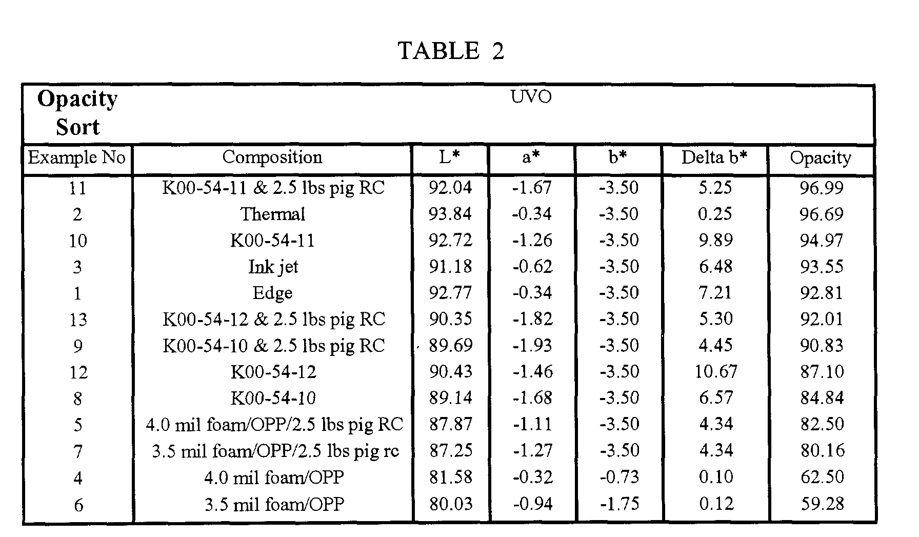
- Table 2 below lists the results of Table 1 but sorted on OPACITY .
- Examples 4 and 6 have significantly lower opacity that that considered acceptable for commercial imaging supports as shown by Examples 1, 2, and 3. There is a dramatic improvement in opacity as one applies a thin coating of pigmented RC to the upper flange. Again, Examples 4 and 6 with an RC coating (Examples 5 and 7 respectively), when compared to Examples 1, 2, and 3, are still not acceptable, but the improvement in opacity is significant. Note also in Examples K00-54-10, 11, and 12 (Examples 8, 10, and 12) that the positioning of the fillers and the concentration of the fillers into a single layer result in an improvement in opacity. The overcoat results in an improvement in opacity of all of the foamed supports.
- Example 11 the arrangement of fillers in Example 11, comprising all of the filler in the middle layer in combination with the foam, has an advantage over Example 12. It is felt that this advantage is due to the larger refractive index difference between the fillers and foam of Example 11 versus that of the fillers and polymer of Example 12, so it can be seen that changes to the type, amount, concentration, and positioning of the fillers and/or layers of the foamed support can control opacity.
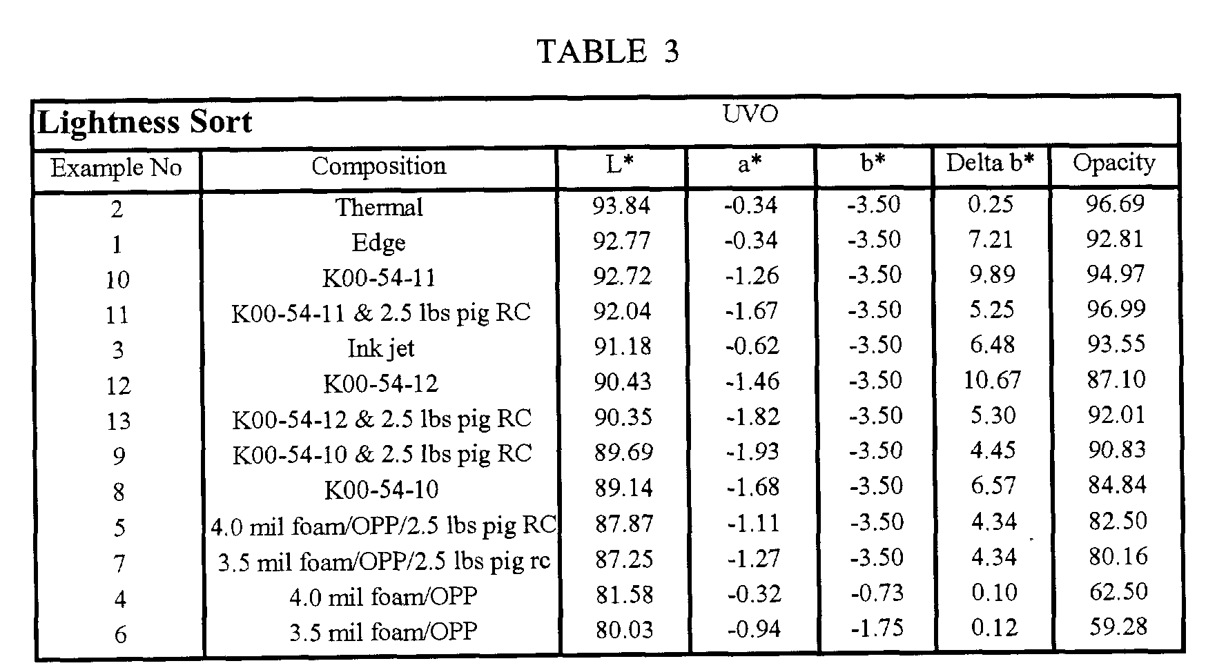
- Table 3 lists the results of Table 1 sorted on LIGHTNESS .
Landscapes
- Physics & Mathematics (AREA)
- Spectroscopy & Molecular Physics (AREA)
- General Physics & Mathematics (AREA)
- Optics & Photonics (AREA)
- Chemical & Material Sciences (AREA)
- Engineering & Computer Science (AREA)
- Materials Engineering (AREA)
- Thermal Transfer Or Thermal Recording In General (AREA)
- Ink Jet Recording Methods And Recording Media Thereof (AREA)
- Laminated Bodies (AREA)
Abstract
Description
| UVO | ||||||
| Example No | Composition | L* | a* | b* | Delta b* | Opacity |
| 1 | Edge | 92.77 | -0.34 | -3.50 | 7.21 | 92.81 |
| 2 | Thermal | 93.84 | -0.34 | -3.50 | 0.25 | 96.69 |
| 3 | Ink jet | 91.18 | -0.62 | -3.50 | 6.48 | 93.55 |
| 4 | 4.0 mil foam/OPP | 81.58 | -0.32 | -0.73 | 0.10 | 62.50 |
| 5 | 4.0 mil foam/OPP/2.5 lbs pig RC | 87.87 | -1.11 | -3.50 | 4.34 | 82.50 |
| 6 | 3.5 mil foam/OPP | 80.03 | -0.94 | -1.75 | 0.12 | 59.28 |
| 7 | 3.5 mil foam/OPP/2.5 lbs pig RC | 87.25 | -1.27 | -3.50 | 4.34 | 80.16 |
| 8 | K00-54-10 | 89.14 | -1.68 | -3.50 | 6.57 | 84.84 |
| 9 | K00-54-10 & 2.5 lbs pig RC | 89.69 | -1.93 | -3.50 | 4.45 | 90.83 |
| 10 | K00-54-11 | 92.72 | -1.26 | -3.50 | 9.89 | 94.97 |
| 11 | K00-54-11 & 2.5 lbs pig RC | 92.04 | -1.67 | -3.50 | 5.25 | 96.99 |
| 12 | K00-54-12 | 90.43 | -1.46 | -3.50 | 10.67 | 87.10 |
| 13 | K00-54-12 & 2.5 lbs pig RC | 90.35 | -1.82 | -3.50 | 5.30 | 92.01 |
Claims (10)
- An imaging member comprising an imaging layer and a base wherein said base comprises a closed cell foam core sheet and adhered thereto an upper and lower flange sheet, and wherein said imaging member has a stiffness of between 50 and 250 millinewtons and at least one layer of said base comprises whitening agent and said element has L* of greater than 90.4.
- The imaging member of Claim 1 wherein the upper surface of said base has an average roughness of between 0.1 µm and 1.1 µm.
- The imaging member of Claim 1 or 2 wherein said foam core sheet has a thickness of between 25 and 175 µm.
- The imaging member of any of Claims 1-3 wherein said flange sheets comprise polymer sheets.
- The imaging member of any of Claims 1-4 wherein said polymer sheets are formed integrally with said foam core sheet.
- The imaging member of any of Claims 1-5 wherein said foam core sheet comprises polyolefin.
- The imaging member of any of Claims 1-6 wherein said base has a thickness of between 100 and 400 µm.
- The imaging member of Claim 4 wherein said polymer sheets comprise biaxially oriented polyolefin sheets.
- The imaging member of any of Claims 1-8 further comprising at least one photosensitive silver halide layer.
- The imaging member of any of Claims 1-8 wherein said imaging layer comprises an ink jet receiving layer.
Applications Claiming Priority (2)
| Application Number | Priority Date | Filing Date | Title |
|---|---|---|---|
| US09/723,682 US6447976B1 (en) | 2000-11-28 | 2000-11-28 | Foam core imaging element with improved optical performance |
| US723682 | 2000-11-28 |
Publications (2)
| Publication Number | Publication Date |
|---|---|
| EP1209518A2 true EP1209518A2 (en) | 2002-05-29 |
| EP1209518A3 EP1209518A3 (en) | 2003-05-21 |
Family
ID=24907246
Family Applications (1)
| Application Number | Title | Priority Date | Filing Date |
|---|---|---|---|
| EP01204392A Withdrawn EP1209518A3 (en) | 2000-11-28 | 2001-11-16 | Foam core imaging element with improved optical performance |
Country Status (3)
| Country | Link |
|---|---|
| US (1) | US6447976B1 (en) |
| EP (1) | EP1209518A3 (en) |
| JP (1) | JP2002219764A (en) |
Cited By (5)
| Publication number | Priority date | Publication date | Assignee | Title |
|---|---|---|---|---|
| WO2003106183A1 (en) * | 2002-06-18 | 2003-12-24 | 3M Innovative Properties Company | Ink-receptive foam article |
| WO2004060650A1 (en) * | 2002-12-31 | 2004-07-22 | Exxonmobil Oil Corporation | Multilayer polyolefin substrate with low density core and stiff outer layers |
| EP1326135A3 (en) * | 2001-12-28 | 2006-06-07 | Eastman Kodak Company | Imaging member and method of cutting an imaging member |
| US7655296B2 (en) | 2003-04-10 | 2010-02-02 | 3M Innovative Properties Company | Ink-receptive foam article |
| US7820282B2 (en) | 2003-04-10 | 2010-10-26 | 3M Innovative Properties Company | Foam security substrate |
Families Citing this family (25)
| Publication number | Priority date | Publication date | Assignee | Title |
|---|---|---|---|---|
| JPH11105128A (en) * | 1997-09-30 | 1999-04-20 | Asahi Optical Co Ltd | Method for producing porous film |
| US6656671B1 (en) * | 1998-11-20 | 2003-12-02 | Eastman Kodak Company | Photographic element with voided cushioning layer |
| FR2804784B1 (en) * | 2000-02-04 | 2003-04-11 | Novatec | UNIVERSAL PROCESS FOR THE IDENTIFICATION AND AUTHENTICATION OF OBJECTS, PLANTS OR LIVING BEINGS |
| US6514659B1 (en) | 2000-11-28 | 2003-02-04 | Eastman Kodak Company | Foam core imaging member with glossy surface |
| US20040037980A1 (en) * | 2001-06-18 | 2004-02-26 | Appleton Papers Inc. | Insulated beverage or food container stock |
| US7179523B2 (en) * | 2001-12-28 | 2007-02-20 | Eastman Kodak Company | Imaging element having improved crack propagation during conversion |
| US20030203184A1 (en) * | 2002-04-24 | 2003-10-30 | Suresh Sunderrajan | Process to make a sheet material with cells and voids |
| US6762003B2 (en) * | 2002-05-24 | 2004-07-13 | Eastman Kodak Company | Imaging member with amorphous hydrocarbon resin |
| US6566033B1 (en) * | 2002-06-20 | 2003-05-20 | Eastman Kodak Company | Conductive foam core imaging member |
| US7135258B2 (en) * | 2002-09-26 | 2006-11-14 | Eastman Kodak Company | Imaging member adhered to vacuous core base |
| US7445736B2 (en) * | 2002-12-23 | 2008-11-04 | Eastman Kodak Company | Embossed indicia on foam core imaging media |
| US20040119189A1 (en) * | 2002-12-23 | 2004-06-24 | Eastman Kodak Company | Indicia on foam core support media |
| US6699629B1 (en) | 2002-12-23 | 2004-03-02 | Eastman Kodak Company | Process survivable indicia on foam core imaging supports |
| US6818367B2 (en) * | 2003-04-15 | 2004-11-16 | Eastman Kodak Company | Support with reduced optical brightener migration |
| US20050013986A1 (en) * | 2003-05-29 | 2005-01-20 | Buechler Troy Raymond | Optical brighteners for display panels |
| US20050084789A1 (en) * | 2003-10-17 | 2005-04-21 | Eastman Kodak Company | Pressure developable imaging element with improved support |
| US20080075859A1 (en) * | 2004-01-20 | 2008-03-27 | Baker Richard J | Printing, Depositing, or Coating On Flowable Substrates |
| US8753702B2 (en) * | 2004-01-20 | 2014-06-17 | Fujifilm Dimatix, Inc. | Printing on edible substrates |
| US7585557B2 (en) * | 2004-02-17 | 2009-09-08 | Eastman Kodak Company | Foam core imaging element with gradient density core |
| US7037634B2 (en) * | 2004-02-27 | 2006-05-02 | Eastman Kodak Company | Polymer foam surface smoothing materials and method |
| US7033723B2 (en) * | 2004-02-27 | 2006-04-25 | Eastman Kodak Company | Surface roughness frequency to control pits on foam core imaging supports |
| US20070008790A1 (en) * | 2004-05-26 | 2007-01-11 | Buechler Troy R | Optical brighteners for display panels |
| US7838106B2 (en) | 2007-12-19 | 2010-11-23 | Eastman Kodak Company | Foamed image receiver |
| JP5396623B2 (en) * | 2009-06-12 | 2014-01-22 | 西川ゴム工業株式会社 | Rubber product |
| EP4041525A4 (en) * | 2019-10-07 | 2023-11-01 | MuCell Extrusion LLC | LIGHTWEIGHT MULTILAYER FOAM FILM WITH IMPROVED PERCEIVED SURFACE WHITENESS |
Family Cites Families (16)
| Publication number | Priority date | Publication date | Assignee | Title |
|---|---|---|---|---|
| JPS5780047A (en) | 1980-11-04 | 1982-05-19 | Fuji Photo Film Co Ltd | Laminated sheet |
| JPS59201848A (en) | 1983-05-02 | 1984-11-15 | 富士写真フイルム株式会社 | Laminated film |
| US4533578A (en) | 1983-08-30 | 1985-08-06 | Mobil Oil Corporation | Sandwich foam coextrusion for high performance polyolefin trash bags |
| JPS60196335A (en) | 1984-03-21 | 1985-10-04 | 富士写真フイルム株式会社 | Laminated film |
| US4832775A (en) | 1987-05-20 | 1989-05-23 | Mobil Oil Corporation | Composite structure based on polystyrene foam and oriented polypropylene film and thermo-formed articles fabricated therefrom |
| JPH0622962B2 (en) | 1988-09-19 | 1994-03-30 | ダイアホイルヘキスト株式会社 | Laminated film |
| US5393603A (en) | 1992-03-04 | 1995-02-28 | Oji Yuki Goseishi Co., Ltd. | Laminated resin sheet and process for producing the same |
| US5861201A (en) | 1994-02-15 | 1999-01-19 | Owens-Illinois Labels Inc. | Multilayer label material |
| JPH09179241A (en) | 1995-12-26 | 1997-07-11 | Fuji Photo Film Co Ltd | Manufacture of photographic print paper base |
| US5851651A (en) | 1996-11-20 | 1998-12-22 | Westvaco Corporation | Coating for inkjet recording |
| US5888683A (en) * | 1997-05-23 | 1999-03-30 | Eastman Kodak Company | Roughness elimination by control of strength of polymer sheet in relation to base paper |
| US5866282A (en) | 1997-05-23 | 1999-02-02 | Eastman Kodak Company | Composite photographic material with laminated biaxially oriented polyolefin sheets |
| US5888643A (en) * | 1997-05-23 | 1999-03-30 | Eastman Kodak Company | Controlling bending stiffness in photographic paper |
| US6153367A (en) | 1998-10-26 | 2000-11-28 | Eastman Kodak Company | Biaxially oriented polyolefin paperless imaging material |
| US6030742A (en) * | 1998-11-23 | 2000-02-29 | Eastman Kodak Company | Superior photographic elements including biaxially oriented polyolefin sheets |
| EP1288723A4 (en) * | 2000-05-15 | 2006-09-20 | Yupo Corp | PRINTING SHEET FOR ELECTROPHOTOGRAPHY AND PAPER FOR LABEL |
-
2000
- 2000-11-28 US US09/723,682 patent/US6447976B1/en not_active Expired - Fee Related
-
2001
- 2001-11-16 EP EP01204392A patent/EP1209518A3/en not_active Withdrawn
- 2001-11-26 JP JP2001359470A patent/JP2002219764A/en active Pending
Cited By (7)
| Publication number | Priority date | Publication date | Assignee | Title |
|---|---|---|---|---|
| EP1326135A3 (en) * | 2001-12-28 | 2006-06-07 | Eastman Kodak Company | Imaging member and method of cutting an imaging member |
| US7143674B2 (en) * | 2001-12-28 | 2006-12-05 | Eastman Kodak Company | Imaging element having improved crack propagation during conversion |
| WO2003106183A1 (en) * | 2002-06-18 | 2003-12-24 | 3M Innovative Properties Company | Ink-receptive foam article |
| WO2004060650A1 (en) * | 2002-12-31 | 2004-07-22 | Exxonmobil Oil Corporation | Multilayer polyolefin substrate with low density core and stiff outer layers |
| US6946203B1 (en) | 2002-12-31 | 2005-09-20 | Exxon Mobil Oil Corporation | Multilayer polyolefin substrate with low density core and stiff outer layers |
| US7655296B2 (en) | 2003-04-10 | 2010-02-02 | 3M Innovative Properties Company | Ink-receptive foam article |
| US7820282B2 (en) | 2003-04-10 | 2010-10-26 | 3M Innovative Properties Company | Foam security substrate |
Also Published As
| Publication number | Publication date |
|---|---|
| EP1209518A3 (en) | 2003-05-21 |
| US6447976B1 (en) | 2002-09-10 |
| JP2002219764A (en) | 2002-08-06 |
Similar Documents
| Publication | Publication Date | Title |
|---|---|---|
| US6447976B1 (en) | Foam core imaging element with improved optical performance | |
| US7585557B2 (en) | Foam core imaging element with gradient density core | |
| EP1209519B1 (en) | Foam core imaging member with glossy surface | |
| US6566033B1 (en) | Conductive foam core imaging member | |
| US6273984B1 (en) | Lamination with curl control | |
| US6537656B1 (en) | Foam core imaging member | |
| US7445736B2 (en) | Embossed indicia on foam core imaging media | |
| US6762003B2 (en) | Imaging member with amorphous hydrocarbon resin | |
| US7094460B2 (en) | Imaging element with improved surface and stiffness | |
| US20040119189A1 (en) | Indicia on foam core support media | |
| US7037634B2 (en) | Polymer foam surface smoothing materials and method | |
| US7143674B2 (en) | Imaging element having improved crack propagation during conversion | |
| US6699629B1 (en) | Process survivable indicia on foam core imaging supports | |
| US7179523B2 (en) | Imaging element having improved crack propagation during conversion | |
| US20030203184A1 (en) | Process to make a sheet material with cells and voids | |
| EP1139172A2 (en) | Imaging element including brace and mechanical holding means | |
| WO2004092827A1 (en) | Support with reduced optical brightener migration | |
| US7033723B2 (en) | Surface roughness frequency to control pits on foam core imaging supports |
Legal Events
| Date | Code | Title | Description |
|---|---|---|---|
| PUAI | Public reference made under article 153(3) epc to a published international application that has entered the european phase |
Free format text: ORIGINAL CODE: 0009012 |
|
| AK | Designated contracting states |
Kind code of ref document: A2 Designated state(s): AT BE CH CY DE DK ES FI FR GB GR IE IT LI LU MC NL PT SE TR |
|
| AX | Request for extension of the european patent |
Free format text: AL;LT;LV;MK;RO;SI |
|
| PUAL | Search report despatched |
Free format text: ORIGINAL CODE: 0009013 |
|
| AK | Designated contracting states |
Designated state(s): AT BE CH CY DE DK ES FI FR GB GR IE IT LI LU MC NL PT SE TR |
|
| AX | Request for extension of the european patent |
Extension state: AL LT LV MK RO SI |
|
| 17P | Request for examination filed |
Effective date: 20031014 |
|
| AKX | Designation fees paid |
Designated state(s): DE FR GB |
|
| 17Q | First examination report despatched |
Effective date: 20050406 |
|
| STAA | Information on the status of an ep patent application or granted ep patent |
Free format text: STATUS: THE APPLICATION IS DEEMED TO BE WITHDRAWN |
|
| 18D | Application deemed to be withdrawn |
Effective date: 20050817 |