EP1209395A1 - Dispositif de sécurité pour raccord de tuyauterie - Google Patents
Dispositif de sécurité pour raccord de tuyauterie Download PDFInfo
- Publication number
- EP1209395A1 EP1209395A1 EP01402804A EP01402804A EP1209395A1 EP 1209395 A1 EP1209395 A1 EP 1209395A1 EP 01402804 A EP01402804 A EP 01402804A EP 01402804 A EP01402804 A EP 01402804A EP 1209395 A1 EP1209395 A1 EP 1209395A1
- Authority
- EP
- European Patent Office
- Prior art keywords
- flange
- pair
- predetermined distance
- retaining
- piping
- Prior art date
- Legal status (The legal status is an assumption and is not a legal conclusion. Google has not performed a legal analysis and makes no representation as to the accuracy of the status listed.)
- Granted
Links
- 230000008878 coupling Effects 0.000 title 1
- 238000010168 coupling process Methods 0.000 title 1
- 238000005859 coupling reaction Methods 0.000 title 1
- 239000012530 fluid Substances 0.000 claims abstract description 11
- XKRFYHLGVUSROY-UHFFFAOYSA-N Argon Chemical compound [Ar] XKRFYHLGVUSROY-UHFFFAOYSA-N 0.000 description 6
- IJGRMHOSHXDMSA-UHFFFAOYSA-N Atomic nitrogen Chemical compound N#N IJGRMHOSHXDMSA-UHFFFAOYSA-N 0.000 description 6
- 239000007789 gas Substances 0.000 description 5
- 229910052786 argon Inorganic materials 0.000 description 3
- QVGXLLKOCUKJST-UHFFFAOYSA-N atomic oxygen Chemical compound [O] QVGXLLKOCUKJST-UHFFFAOYSA-N 0.000 description 3
- 229910052757 nitrogen Inorganic materials 0.000 description 3
- 239000001301 oxygen Substances 0.000 description 3
- 229910052760 oxygen Inorganic materials 0.000 description 3
- 239000011261 inert gas Substances 0.000 description 2
- 229910001369 Brass Inorganic materials 0.000 description 1
- 239000004952 Polyamide Substances 0.000 description 1
- 229910000831 Steel Inorganic materials 0.000 description 1
- 230000004308 accommodation Effects 0.000 description 1
- 239000010951 brass Substances 0.000 description 1
- 239000000835 fiber Substances 0.000 description 1
- 238000005259 measurement Methods 0.000 description 1
- 239000002184 metal Substances 0.000 description 1
- 239000000203 mixture Substances 0.000 description 1
- 238000012986 modification Methods 0.000 description 1
- 230000004048 modification Effects 0.000 description 1
- 229920002647 polyamide Polymers 0.000 description 1
- 239000010959 steel Substances 0.000 description 1
Images


Classifications
-
- F—MECHANICAL ENGINEERING; LIGHTING; HEATING; WEAPONS; BLASTING
- F16—ENGINEERING ELEMENTS AND UNITS; GENERAL MEASURES FOR PRODUCING AND MAINTAINING EFFECTIVE FUNCTIONING OF MACHINES OR INSTALLATIONS; THERMAL INSULATION IN GENERAL
- F16K—VALVES; TAPS; COCKS; ACTUATING-FLOATS; DEVICES FOR VENTING OR AERATING
- F16K35/00—Means to prevent accidental or unauthorised actuation
-
- F—MECHANICAL ENGINEERING; LIGHTING; HEATING; WEAPONS; BLASTING
- F16—ENGINEERING ELEMENTS AND UNITS; GENERAL MEASURES FOR PRODUCING AND MAINTAINING EFFECTIVE FUNCTIONING OF MACHINES OR INSTALLATIONS; THERMAL INSULATION IN GENERAL
- F16L—PIPES; JOINTS OR FITTINGS FOR PIPES; SUPPORTS FOR PIPES, CABLES OR PROTECTIVE TUBING; MEANS FOR THERMAL INSULATION IN GENERAL
- F16L35/00—Special arrangements used in connection with end fittings of hoses, e.g. safety or protecting devices
-
- F—MECHANICAL ENGINEERING; LIGHTING; HEATING; WEAPONS; BLASTING
- F16—ENGINEERING ELEMENTS AND UNITS; GENERAL MEASURES FOR PRODUCING AND MAINTAINING EFFECTIVE FUNCTIONING OF MACHINES OR INSTALLATIONS; THERMAL INSULATION IN GENERAL
- F16L—PIPES; JOINTS OR FITTINGS FOR PIPES; SUPPORTS FOR PIPES, CABLES OR PROTECTIVE TUBING; MEANS FOR THERMAL INSULATION IN GENERAL
- F16L2201/00—Special arrangements for pipe couplings
- F16L2201/20—Safety or protective couplings
-
- F—MECHANICAL ENGINEERING; LIGHTING; HEATING; WEAPONS; BLASTING
- F16—ENGINEERING ELEMENTS AND UNITS; GENERAL MEASURES FOR PRODUCING AND MAINTAINING EFFECTIVE FUNCTIONING OF MACHINES OR INSTALLATIONS; THERMAL INSULATION IN GENERAL
- F16L—PIPES; JOINTS OR FITTINGS FOR PIPES; SUPPORTS FOR PIPES, CABLES OR PROTECTIVE TUBING; MEANS FOR THERMAL INSULATION IN GENERAL
- F16L2201/00—Special arrangements for pipe couplings
- F16L2201/60—Identification or marking
-
- Y—GENERAL TAGGING OF NEW TECHNOLOGICAL DEVELOPMENTS; GENERAL TAGGING OF CROSS-SECTIONAL TECHNOLOGIES SPANNING OVER SEVERAL SECTIONS OF THE IPC; TECHNICAL SUBJECTS COVERED BY FORMER USPC CROSS-REFERENCE ART COLLECTIONS [XRACs] AND DIGESTS
- Y10—TECHNICAL SUBJECTS COVERED BY FORMER USPC
- Y10S—TECHNICAL SUBJECTS COVERED BY FORMER USPC CROSS-REFERENCE ART COLLECTIONS [XRACs] AND DIGESTS
- Y10S285/00—Pipe joints or couplings
- Y10S285/904—Cryogenic
-
- Y—GENERAL TAGGING OF NEW TECHNOLOGICAL DEVELOPMENTS; GENERAL TAGGING OF CROSS-SECTIONAL TECHNOLOGIES SPANNING OVER SEVERAL SECTIONS OF THE IPC; TECHNICAL SUBJECTS COVERED BY FORMER USPC CROSS-REFERENCE ART COLLECTIONS [XRACs] AND DIGESTS
- Y10—TECHNICAL SUBJECTS COVERED BY FORMER USPC
- Y10S—TECHNICAL SUBJECTS COVERED BY FORMER USPC CROSS-REFERENCE ART COLLECTIONS [XRACs] AND DIGESTS
- Y10S285/00—Pipe joints or couplings
- Y10S285/914—Irreversible
Definitions
- the present invention relates to safety devices for cryogenic fluid pipe fittings with two ends connecting threads extending a central body part, and more especially the safety devices for pipe fittings of filling and / or racking of cryogenic fluid tanks.
- Pipe fittings for cryogenic fluids are sized differently depending on the fluids concerned, classified by kind according to their degree of dangerousness, typically either an inert gas such that nitrogen or argon is oxygen. Connections must be capable of being changed in the event of damage or change of the fluid to be stored in the tank, which can cause uncontrolled reversals.
- the object of the present invention is to provide a device for security preventing such uncontrolled reversals and allowing identify quickly and reliably the various fittings, limiting thus the risk of improper connections.
- the part body of the fitting comprises a flange comprising at least one pair orifices spaced a predetermined distance apart
- the safety device further comprising a retainer comprising a front part formed with a pair of orifices spaced apart from said distance predetermined and used to secure the retaining part with the flange, and a rear part capable of cooperating in abutment with a element of said piping on which the fitting is mounted.
- the present invention also relates to a reservoir for cryogenic fluid, typically liquefied air gas, comprising at least minus piping fitted with a safety device as defined above.
- a cryogenic fluid reservoir generally designated by the reference 1
- a handling ramp 2 comprising at its upper part, protected by a handling ramp 2, several filling or withdrawal pipes 3 1 , 3 2 , 3 3 each provided with a fluid passage control valve 4.
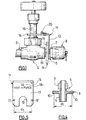
- a fitting 5 used for connection of hose 3 with external piping (not shown).
- the connector 5 made typically made of brass, has a rear threaded part 6 intended for be screwed into valve 4 and a front threaded part 7 intended for connection with said external piping and normally protected, before said connection, by a removable cap 8.
- the connector 5 comprises, between the threaded parts 6 and 7, at least one flange 9 extending radially outward and provided with at least one pair (typically two pairs) of orifices crossing 10 apart by a predetermined distance d 1 .
- the security device further comprises a retainer or stirrup 11, advantageously made of steel stainless, having, in the embodiment shown, a generally L-shaped with a front wing 12 provided with a cutout in U 13 intended to come to engage in the draft of the thread 7 of the connection 5, in front of the flange 9, and a rear wing 14, also provided with a wider U-shaped cutout 15 to surround, in mounting configuration, the steering wheel guide barrel 16 of valve 4.
- a retainer or stirrup 11 advantageously made of steel stainless, having, in the embodiment shown, a generally L-shaped with a front wing 12 provided with a cutout in U 13 intended to come to engage in the draft of the thread 7 of the connection 5, in front of the flange 9, and a rear wing 14, also provided with a wider U-shaped cutout 15 to surround, in mounting configuration, the steering wheel guide barrel 16 of valve 4.
- the front wing 12 of the stirrup comprises on either side of the U-shaped cutout 13, a pair of orifices 17 spaced the same distance d 1 as the pair d holes 10 of flange 9 of fitting 5.
- the spacing d is chosen from a group of at least two different spacings, namely typically a spacing d 1 for an oxygen connection (FIGS. 4 and 5) and a different spacing d 2 for an inert gas such as nitrogen or argon (FIG. 6).
- each stirrup 11 has a clear marking 18 i corresponding to the spacing d i , thus making it possible to immediately pair the stirrup 11 and the fitting 5 corresponding to the gas concerned.
- the present invention finds a particular application in liquefied air gas tanks, typically oxygen on the one hand, argon and nitrogen on the other.
Landscapes
- Engineering & Computer Science (AREA)
- General Engineering & Computer Science (AREA)
- Mechanical Engineering (AREA)
- Filling Or Discharging Of Gas Storage Vessels (AREA)
- Quick-Acting Or Multi-Walled Pipe Joints (AREA)
Abstract
Description
- la pièce de retenue porte un marquage
- la distance prédéterminée est sélectionnée dans un groupe d'au moins deux distances différentes, correspondant typiquement à des genres de gaz différents
- le marquage de la pièce de retenue est associée à une desdites distances prédéterminées.
- la figure 1 est une vue de côté d'un mode de réalisation d'un dispositif de sécurité selon l'invention ;
- les figures 2 et 3 sont des vues respectivement de côté et de dessus d'un réservoir cryogénique multi-sorties équipé de dispositifs de sécurité selon la figure 1 ;
- la figure 4 est une vue en coupe longitudinale d'un raccord selon l'invention ;
- les figures 5 et 6 sont des vues de face de deux pièces de retenue différenciées selon l'invention.
Claims (10)
- Dispositif de sécurité pour raccord de tuyauterie de fluide cryogénique comprenant deux extrémités filetées prolongeant une partie de corps centrale, caractérisé en ce que la partie de corps centrale comporte une bride (9) comportant au moins une paire d'orifices (10) espacés d'une distance prédéterminée (di) et en ce qu'il comporte une pièce de retenue (11) comportant une partie avant (12) formée avec une paire d'orifices (17) espacés de ladite distance prédéterminée (di) et servant à la solidarisation avec la bride (9), et une partie arrière (14) susceptible de coopérer en butée avec un élément (7) de ladite tuyauterie.
- Dispositif selon la revendication 1, caractérisé en ce que la pièce de retenue (11) a une forme générale en L.
- Dispositif selon la revendication 1 ou la revendication 2, caractérisé en ce que l'élément de tuyauterie est une vanne (4,16).
- Dispositif selon l'une des revendications précédentes, caractérisé en ce que la partie arrière (14) de la pièce de retenue a une forme en U (15) pour recevoir une partie (16) de la vanne (4).
- Dispositif selon l'une des revendications précédentes, caractérisé en ce que la pièce de retenue (11) porte un marquage (18i).
- Dispositif selon l'une des revendications précédentes, caractérisé en ce que la distance prédéterminée (di) est sélectionnée dans un groupe d'au moins deux distances différentes (d1, d2).
- Dispositif selon la revendication 5 et la revendication 6, caractérisé en ce que le marquage (18i) est associé à une desdites distances prédéterminées (di).
- Réservoir de fluide cryogénique comprenant au moins une tuyauterie (3) équipé d'un dispositif de sécurité selon l'une des revendications précédentes.
- Réservoir selon la revendication 8 comprenant au moins deux tuyaux (31, 33) pourvus chacun d'un dispositif selon une des revendications 1 à 7 dont les pièces de retenue (11) sont reliées les unes aux autres par un lien souple (20).
- Réservoir selon l'une des revendications 8 et 9, caractérisé en ce qu'il contient un gaz de l'air.
Applications Claiming Priority (2)
| Application Number | Priority Date | Filing Date | Title |
|---|---|---|---|
| FR0014721A FR2816690B1 (fr) | 2000-11-15 | 2000-11-15 | Dispositif de securite pour raccord de tuyauterie de fluide cryogenique et reservoir de fluide cryogenique comprenant au moins une tuyauterie equipee d'un tel dispositif de securite |
| FR0014721 | 2000-11-15 |
Publications (2)
| Publication Number | Publication Date |
|---|---|
| EP1209395A1 true EP1209395A1 (fr) | 2002-05-29 |
| EP1209395B1 EP1209395B1 (fr) | 2006-01-18 |
Family
ID=8856489
Family Applications (1)
| Application Number | Title | Priority Date | Filing Date |
|---|---|---|---|
| EP01402804A Expired - Lifetime EP1209395B1 (fr) | 2000-11-15 | 2001-10-29 | Dispositif de sécurité pour raccord de tuyauterie |
Country Status (5)
| Country | Link |
|---|---|
| US (1) | US6641174B2 (fr) |
| EP (1) | EP1209395B1 (fr) |
| AT (1) | ATE316219T1 (fr) |
| DE (1) | DE60116728T2 (fr) |
| FR (1) | FR2816690B1 (fr) |
Families Citing this family (8)
| Publication number | Priority date | Publication date | Assignee | Title |
|---|---|---|---|---|
| US7384056B2 (en) * | 2005-08-18 | 2008-06-10 | Russ Cameron Anderson | Fifth wheel coupler release apparatus |
| US20080238084A1 (en) * | 2007-03-26 | 2008-10-02 | Steven Hung | Basic hoisting ring labeling means |
| CN105673920A (zh) * | 2016-04-19 | 2016-06-15 | 宁波市江北兴达焊割减压仪表厂 | 一种高耐久减压器 |
| CN105697861A (zh) * | 2016-04-19 | 2016-06-22 | 宁波市江北兴达焊割减压仪表厂 | 高耐久的减压器 |
| US11473729B2 (en) * | 2016-10-19 | 2022-10-18 | Chart Inc. | Multiple head dosing arm device, system and method |
| US10451221B2 (en) * | 2016-10-19 | 2019-10-22 | Chart Inc. | Interchangeable dosing arm device, system and method |
| FR3065488B1 (fr) * | 2017-04-20 | 2019-06-28 | Faurecia Systemes D'echappement | Element de ligne d'echappement et procede de fabrication d'un tel element |
| WO2025208170A1 (fr) * | 2024-04-02 | 2025-10-09 | Cij Engineered Pty Ltd | Accessoire d'avertissement de système sous pression |
Citations (3)
| Publication number | Priority date | Publication date | Assignee | Title |
|---|---|---|---|---|
| US3006181A (en) * | 1958-05-15 | 1961-10-31 | Perkins Welding Works | Gate valve locking device |
| US4397332A (en) * | 1981-06-26 | 1983-08-09 | Sample Louis J | Standpipe cap locking means |
| US4736765A (en) * | 1987-04-06 | 1988-04-12 | Camline Services & Supplies Incorporated | Hydrant securing device |
Family Cites Families (12)
| Publication number | Priority date | Publication date | Assignee | Title |
|---|---|---|---|---|
| US3698742A (en) * | 1970-11-23 | 1972-10-17 | Mc Donnell Douglas Corp | Connector with disconnect warning indicator |
| US3864928A (en) * | 1972-12-01 | 1975-02-11 | Union Carbide Corp | All-attitude cryogenic vapor vent system |
| US3813733A (en) * | 1973-02-16 | 1974-06-04 | I Flohr | Safety cable and band |
| US3976095A (en) * | 1975-06-09 | 1976-08-24 | Whitey Research Tool Co. | Operating member locking device |
| US4183562A (en) * | 1977-04-01 | 1980-01-15 | Regan Offshore International, Inc. | Marine riser conduit section coupling means |
| US4108476A (en) * | 1977-04-11 | 1978-08-22 | Krupp Walter H | Precompressed piping system for handling cryogenic fluid |
| IT1122297B (it) * | 1979-07-24 | 1986-04-23 | Bormioli Giorgio | Sistema di connessione flessibile fra tubazioni con sgancio automatico di sicurezza in caso di sollecitazione a trazione |
| US4681134A (en) * | 1986-07-23 | 1987-07-21 | Paris Sr Raymond L | Valve lock |
| US5228474A (en) * | 1991-11-05 | 1993-07-20 | Precision General, Inc. | Flow system disconnect and method |
| US5395140A (en) * | 1993-05-13 | 1995-03-07 | Enhanced Applications, L.C. | Secondary latch and indicator for fluid coupling |
| US5623890A (en) * | 1995-06-01 | 1997-04-29 | Lenske; Gregory D. | Safe exit indicating firehose coupling |
| AU1292299A (en) * | 1997-10-30 | 1999-05-24 | Hill-Rom Medaes, Inc. | Keyed cap for gas outlet valve |
-
2000
- 2000-11-15 FR FR0014721A patent/FR2816690B1/fr not_active Expired - Fee Related
-
2001
- 2001-09-14 US US09/951,635 patent/US6641174B2/en not_active Expired - Fee Related
- 2001-10-29 AT AT01402804T patent/ATE316219T1/de not_active IP Right Cessation
- 2001-10-29 EP EP01402804A patent/EP1209395B1/fr not_active Expired - Lifetime
- 2001-10-29 DE DE60116728T patent/DE60116728T2/de not_active Expired - Fee Related
Patent Citations (3)
| Publication number | Priority date | Publication date | Assignee | Title |
|---|---|---|---|---|
| US3006181A (en) * | 1958-05-15 | 1961-10-31 | Perkins Welding Works | Gate valve locking device |
| US4397332A (en) * | 1981-06-26 | 1983-08-09 | Sample Louis J | Standpipe cap locking means |
| US4736765A (en) * | 1987-04-06 | 1988-04-12 | Camline Services & Supplies Incorporated | Hydrant securing device |
Also Published As
| Publication number | Publication date |
|---|---|
| DE60116728D1 (de) | 2006-04-06 |
| FR2816690B1 (fr) | 2003-01-24 |
| US6641174B2 (en) | 2003-11-04 |
| DE60116728T2 (de) | 2006-11-02 |
| FR2816690A1 (fr) | 2002-05-17 |
| ATE316219T1 (de) | 2006-02-15 |
| US20020056992A1 (en) | 2002-05-16 |
| EP1209395B1 (fr) | 2006-01-18 |
Similar Documents
| Publication | Publication Date | Title |
|---|---|---|
| EP0650005B1 (fr) | Raccordement détachable pour tuyaux souples concentriques | |
| US4674525A (en) | Breakaway hose coupling device | |
| EP1209395B1 (fr) | Dispositif de sécurité pour raccord de tuyauterie | |
| FR3099094A1 (fr) | Système de stockage d’hydrogène | |
| AU2005223687B2 (en) | Refueling assembly having a check valve receptacle and a replaceable fuel receiver for bottom-filled fuel tanks | |
| WO2020071894A1 (fr) | Collet protecteur de valve pour bouteilles de gaz (gpl) | |
| WO2004035129A1 (fr) | Connecteur a usage medical pour conduits de liquide et verrou pour ce connecteur | |
| GB2239664A (en) | End fittings for wire rope | |
| EP3129694B1 (fr) | Ensemble auto-obturant de tuyau flexible bidirectionnel | |
| NZ240724A (en) | Pipe block with resilient shaft and rod; rod is releasable from the shaft | |
| US2732169A (en) | matteo | |
| FR3072756A1 (fr) | Dispositif de raccord tubulaire comprenant un indicateur d’etat de montage | |
| US11408540B2 (en) | Tube coupling assembly | |
| US6955183B2 (en) | Pressure tank valve socket | |
| FR2625545A1 (fr) | Dispositif de detrompeurs inviolables pour assemblage de prises de fluides medicaux sur douilles a braser | |
| FR2507574A1 (fr) | Chapeau pour bouteille de stockage de gaz liquefie | |
| EP0475328B1 (fr) | Dispositif permettant de limiter une fuite en cas de rupture d'une tuyauterie | |
| US775929A (en) | Valve. | |
| WO2001059500A1 (fr) | Manchon de fixation pour cables optiques | |
| CN216201469U (zh) | 高安全性的快速接头 | |
| EP3855058B1 (fr) | Dispositif de raccord tubulaire | |
| FR2561214A1 (fr) | Reservoir pourvu d'une conduite de degazage a fermeture de securite | |
| FR2786231A1 (fr) | Dispositif de securisation pour organe de solidarisation | |
| GB2246405A (en) | A pipe coupling | |
| EP3922594A1 (fr) | Adaptateur pour mobile-homes |
Legal Events
| Date | Code | Title | Description |
|---|---|---|---|
| PUAI | Public reference made under article 153(3) epc to a published international application that has entered the european phase |
Free format text: ORIGINAL CODE: 0009012 |
|
| AK | Designated contracting states |
Kind code of ref document: A1 Designated state(s): AT BE CH CY DE DK ES FI FR GB GR IE IT LI LU MC NL PT SE TR |
|
| AX | Request for extension of the european patent |
Free format text: AL;LT;LV;MK;RO;SI |
|
| 17P | Request for examination filed |
Effective date: 20021129 |
|
| AKX | Designation fees paid |
Designated state(s): AT BE CH CY DE DK ES FI FR GB GR IE IT LI LU MC NL PT SE TR |
|
| 17Q | First examination report despatched |
Effective date: 20041008 |
|
| GRAP | Despatch of communication of intention to grant a patent |
Free format text: ORIGINAL CODE: EPIDOSNIGR1 |
|
| GRAS | Grant fee paid |
Free format text: ORIGINAL CODE: EPIDOSNIGR3 |
|
| GRAA | (expected) grant |
Free format text: ORIGINAL CODE: 0009210 |
|
| AK | Designated contracting states |
Kind code of ref document: B1 Designated state(s): AT BE CH CY DE DK ES FI FR GB GR IE IT LI LU MC NL PT SE TR |
|
| PG25 | Lapsed in a contracting state [announced via postgrant information from national office to epo] |
Ref country code: IT Free format text: LAPSE BECAUSE OF FAILURE TO SUBMIT A TRANSLATION OF THE DESCRIPTION OR TO PAY THE FEE WITHIN THE PRESCRIBED TIME-LIMIT;WARNING: LAPSES OF ITALIAN PATENTS WITH EFFECTIVE DATE BEFORE 2007 MAY HAVE OCCURRED AT ANY TIME BEFORE 2007. THE CORRECT EFFECTIVE DATE MAY BE DIFFERENT FROM THE ONE RECORDED. Effective date: 20060118 Ref country code: FI Free format text: LAPSE BECAUSE OF FAILURE TO SUBMIT A TRANSLATION OF THE DESCRIPTION OR TO PAY THE FEE WITHIN THE PRESCRIBED TIME-LIMIT Effective date: 20060118 Ref country code: IE Free format text: LAPSE BECAUSE OF FAILURE TO SUBMIT A TRANSLATION OF THE DESCRIPTION OR TO PAY THE FEE WITHIN THE PRESCRIBED TIME-LIMIT Effective date: 20060118 Ref country code: GB Free format text: LAPSE BECAUSE OF FAILURE TO SUBMIT A TRANSLATION OF THE DESCRIPTION OR TO PAY THE FEE WITHIN THE PRESCRIBED TIME-LIMIT Effective date: 20060118 Ref country code: NL Free format text: LAPSE BECAUSE OF FAILURE TO SUBMIT A TRANSLATION OF THE DESCRIPTION OR TO PAY THE FEE WITHIN THE PRESCRIBED TIME-LIMIT Effective date: 20060118 Ref country code: AT Free format text: LAPSE BECAUSE OF FAILURE TO SUBMIT A TRANSLATION OF THE DESCRIPTION OR TO PAY THE FEE WITHIN THE PRESCRIBED TIME-LIMIT Effective date: 20060118 |
|
| REG | Reference to a national code |
Ref country code: GB Ref legal event code: FG4D Free format text: NOT ENGLISH |
|
| REG | Reference to a national code |
Ref country code: CH Ref legal event code: EP |
|
| REG | Reference to a national code |
Ref country code: IE Ref legal event code: FG4D Free format text: LANGUAGE OF EP DOCUMENT: FRENCH |
|
| REF | Corresponds to: |
Ref document number: 60116728 Country of ref document: DE Date of ref document: 20060406 Kind code of ref document: P |
|
| PG25 | Lapsed in a contracting state [announced via postgrant information from national office to epo] |
Ref country code: SE Free format text: LAPSE BECAUSE OF FAILURE TO SUBMIT A TRANSLATION OF THE DESCRIPTION OR TO PAY THE FEE WITHIN THE PRESCRIBED TIME-LIMIT Effective date: 20060418 Ref country code: DK Free format text: LAPSE BECAUSE OF FAILURE TO SUBMIT A TRANSLATION OF THE DESCRIPTION OR TO PAY THE FEE WITHIN THE PRESCRIBED TIME-LIMIT Effective date: 20060418 |
|
| PG25 | Lapsed in a contracting state [announced via postgrant information from national office to epo] |
Ref country code: ES Free format text: LAPSE BECAUSE OF FAILURE TO SUBMIT A TRANSLATION OF THE DESCRIPTION OR TO PAY THE FEE WITHIN THE PRESCRIBED TIME-LIMIT Effective date: 20060429 |
|
| PG25 | Lapsed in a contracting state [announced via postgrant information from national office to epo] |
Ref country code: PT Free format text: LAPSE BECAUSE OF FAILURE TO SUBMIT A TRANSLATION OF THE DESCRIPTION OR TO PAY THE FEE WITHIN THE PRESCRIBED TIME-LIMIT Effective date: 20060619 |
|
| NLV1 | Nl: lapsed or annulled due to failure to fulfill the requirements of art. 29p and 29m of the patents act | ||
| GBV | Gb: ep patent (uk) treated as always having been void in accordance with gb section 77(7)/1977 [no translation filed] |
Effective date: 20060118 |
|
| REG | Reference to a national code |
Ref country code: IE Ref legal event code: FD4D |
|
| PG25 | Lapsed in a contracting state [announced via postgrant information from national office to epo] |
Ref country code: MC Free format text: LAPSE BECAUSE OF NON-PAYMENT OF DUE FEES Effective date: 20061031 Ref country code: LI Free format text: LAPSE BECAUSE OF NON-PAYMENT OF DUE FEES Effective date: 20061031 Ref country code: CH Free format text: LAPSE BECAUSE OF NON-PAYMENT OF DUE FEES Effective date: 20061031 |
|
| PLBE | No opposition filed within time limit |
Free format text: ORIGINAL CODE: 0009261 |
|
| STAA | Information on the status of an ep patent application or granted ep patent |
Free format text: STATUS: NO OPPOSITION FILED WITHIN TIME LIMIT |
|
| 26N | No opposition filed |
Effective date: 20061019 |
|
| REG | Reference to a national code |
Ref country code: CH Ref legal event code: PL |
|
| PG25 | Lapsed in a contracting state [announced via postgrant information from national office to epo] |
Ref country code: GR Free format text: LAPSE BECAUSE OF FAILURE TO SUBMIT A TRANSLATION OF THE DESCRIPTION OR TO PAY THE FEE WITHIN THE PRESCRIBED TIME-LIMIT Effective date: 20060419 |
|
| PG25 | Lapsed in a contracting state [announced via postgrant information from national office to epo] |
Ref country code: TR Free format text: LAPSE BECAUSE OF FAILURE TO SUBMIT A TRANSLATION OF THE DESCRIPTION OR TO PAY THE FEE WITHIN THE PRESCRIBED TIME-LIMIT Effective date: 20060118 Ref country code: LU Free format text: LAPSE BECAUSE OF NON-PAYMENT OF DUE FEES Effective date: 20061029 |
|
| PG25 | Lapsed in a contracting state [announced via postgrant information from national office to epo] |
Ref country code: CY Free format text: LAPSE BECAUSE OF FAILURE TO SUBMIT A TRANSLATION OF THE DESCRIPTION OR TO PAY THE FEE WITHIN THE PRESCRIBED TIME-LIMIT Effective date: 20060118 |
|
| PGFP | Annual fee paid to national office [announced via postgrant information from national office to epo] |
Ref country code: FR Payment date: 20080922 Year of fee payment: 8 Ref country code: IT Payment date: 20080923 Year of fee payment: 8 |
|
| PGFP | Annual fee paid to national office [announced via postgrant information from national office to epo] |
Ref country code: DE Payment date: 20080923 Year of fee payment: 8 |
|
| PGFP | Annual fee paid to national office [announced via postgrant information from national office to epo] |
Ref country code: BE Payment date: 20081003 Year of fee payment: 8 |
|
| BERE | Be: lapsed |
Owner name: S.A. L'*AIR LIQUIDE A DIRECTOIRE ET CONSEIL DE SU Effective date: 20091031 |
|
| REG | Reference to a national code |
Ref country code: FR Ref legal event code: ST Effective date: 20100630 |
|
| PG25 | Lapsed in a contracting state [announced via postgrant information from national office to epo] |
Ref country code: DE Free format text: LAPSE BECAUSE OF NON-PAYMENT OF DUE FEES Effective date: 20100501 Ref country code: FR Free format text: LAPSE BECAUSE OF NON-PAYMENT OF DUE FEES Effective date: 20091102 |
|
| PG25 | Lapsed in a contracting state [announced via postgrant information from national office to epo] |
Ref country code: BE Free format text: LAPSE BECAUSE OF NON-PAYMENT OF DUE FEES Effective date: 20091031 |
|
| PG25 | Lapsed in a contracting state [announced via postgrant information from national office to epo] |
Ref country code: IT Free format text: LAPSE BECAUSE OF NON-PAYMENT OF DUE FEES Effective date: 20091029 |